Table of Contents
Advertisement
Quick Links
Advertisement
Table of Contents

Related Manuals for JUKI MEB-3200C


Summary of Contents for JUKI MEB-3200C
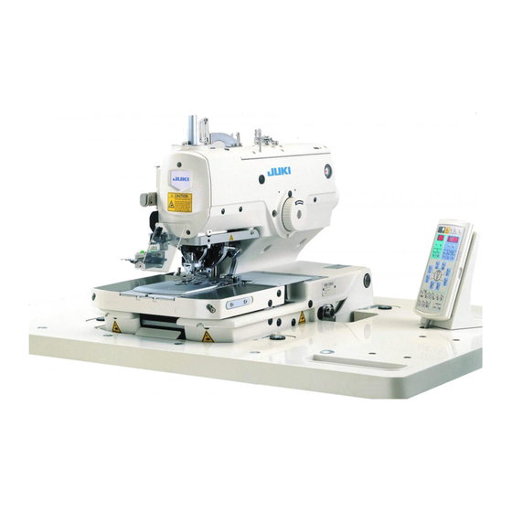
- Page 1 MEB-3200C Needle thread clamp unit INSTRUCTION MANUAL...
-
Page 2: Table Of Contents
CONTENTS 1. BEFORE INSTALLATION AND OPERATION OF THE NEEDLE THREAD CLAMP UNIT .................... 1 (1) How to install the needle thread clamp unit (when the needle thread guide (32051708) is installed) ..................1 (2) How to install the needle thread clamp unit (when the needle thread guide (40023465) is installed) .................. -
Page 3: Before Installation And Operation Of The Needle Thread Clamp Unit
1. BEFORE INSTALLATION AND OPERATION OF THE NEEDLE THREAD CLAMP UNIT (1) How to install the needle thread clamp unit (when the needle thread guide (32051708) is installed) Install needle thread clamp asm. ❼ in the screw hole on the left side A and close to the needle for use. "6. -
Page 4: How To Install The Needle Thread Clamp Unit (When The Needle Thread Guide (40023465) Is Installed)
(2) How to install the needle thread clamp unit (when the needle thread guide (40023465) is installed) Change the installing position of needle thread clamp asm. ❼ to the screw hole on the right side B, (make it apart from the needle), and adjust the clearance between the thread tension disk setscrew and it to 1.5 to 2 mm for use. -
Page 5: Installing The Needle Thread Clamp Unit
2. INSTALLING THE NEEDLE THREAD CLAMP UNIT WARNING : Turn OFF the power before starting the work so as to prevent accidents caused by abrupt start of the sewing machine. 1) Turn OFF the power and the air. 2) Remove the presser units, left and right. 3) Change the installing position of joint ❸... -
Page 6: Connecting The Pneumatic Components
3. CONNECTING THE PNEUMATIC COMPONENTS WARNING : Turn OFF the power before starting the work so as to prevent accidents caused by abrupt start of the sewing machine. 1) Loosen setscrew ❶ in the end block, draw end block ❷ in the direction A to draw out from rail ❸ . 2) Insert solenoid valves ❹... - Page 7 6) Draw the cables up to the bottom of the table as shown in the illustration on the left, and fix them with the clip bands supplied with the unit as accessories. (Fig. 8) 7) Connect the air tube on the side where the needle thread clamp closes to port B (reducing valve of solenoid valve ❹...
-
Page 8: Adjusting The Pneumatic Components
4. ADJUSTING THE PNEUMATIC COMPONENTS (1) Adjusting the thread clamp force (reducing valve) Adjust adjusting screw ❶ of the reducing valve and adjust the thread clamp force in accordance with the thread used so that the thread smoothly ❶ comes off the needle thread clamp during sewing. Standard : Adjust the force by turning adjusting screw ❶... -
Page 9: Setting The Memory Switch
5. SETTING THE MEMORY SWITCH Set the memory switch U59 (needle thread clamp setting) to "1" (enable). ■ Memory switch Description Function Standard Setting Unit value range ー U59 Needle thread clamp 0: Without 1: With 0 to 1 setting U60 Number of stitches 0 to 99 Number of stitches from the start of swing to...
Need help?
Do you have a question about the MEB-3200C and is the answer not in the manual?
Questions and answers