FirePro FP-C2 Operation And Maintenance Manual
Fire control panel
Hide thumbs
Also See for FP-C2:
- Operation and maintenance manual (7 pages) ,
- Operation and installation manual (14 pages) ,
- Quick start manual (2 pages)
Table of Contents
Advertisement
Quick Links
Operation and Maintenance Manual
1.
Introduction .......................................................................................... 2
2.
Operation ............................................................................................. 2
3.
Panel Operation .................................................................................... 2
4.
Installation and Mounting ...................................................................... 3
5.
Installation of FirePro Generators ........................................................... 5
6.
Connecting to Master Fire Panel ............................................................. 6
7.
Maintenance ......................................................................................... 7
8.
Commissioning & Testing ....................................................................... 8
9.
Specifications ........................................................................................ 8
Table of Contents
Fire Control Panel
FP-C2
Rev 7.0
Page | 1
Advertisement
Table of Contents

Related Manuals for FirePro FP-C2


Summary of Contents for FirePro FP-C2
- Page 1 Table of Contents Introduction ..................2 Operation ..................... 2 Panel Operation ..................2 Installation and Mounting ..............3 Installation of FirePro Generators ............5 Connecting to Master Fire Panel ............. 6 Maintenance ..................7 Commissioning & Testing ............... 8 Specifications ..................8...
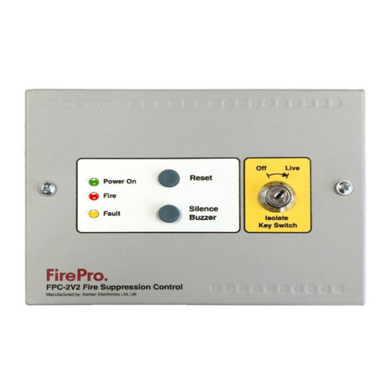
- Page 2 The buzzer may be silenced by pressing the Buzzer Silence button. Upon activation of a linear heat detection cable or smoke detector, the red Fire indicator will be lit, the FirePro Aerosol Generators will operate and immediately discharge extinguishing Aerosol into the protected area, the internal buzzer will sound and the Fault indicator will illuminate, indicating that the Aerosol Generators have fired and need replacing.
- Page 3 FirePro® generators. These test lamps should be removed from the terminals if a FirePro® Aerosol Generator is to be fitted. Any FirePro® generator outputs that are not being used should be left with test lamps fitted.
- Page 4 This can be used to activate a siren or other device. Cabling Requirements Cable Requirements - All cabling in the FirePro Installation MUST be done using 0.75mm shielded Fire Rated Cable. Care taken to ensure that all cables are isolated, and that RF shielding on cable is stripped back to ensure that there is not accidental grounding.
- Page 5 FirePro units and system components installed to allow inspection and maintenance. Locate FirePro units where they are not exposed to mechanical damage, exposed to chemicals, or weather conditions, that may render them inoperative. Protective provisions shall be adopted, if necessary.
- Page 6 This must be done so that FP-C2 is not treated as a regular detection device. When programmed correctly, the FP-C2 will alert the main Sigma XT panel of any alarm or fault states. On the Sigma XT FIP, enter Access Level 2 by turning the key in “Enable Control”...
- Page 7 Power Connection from Sigma XT When FP-C2 is used as a sub-panel from a Sigma XT Control panel it should be connected to a separate Detection Zone as described earlier. Power can be taken from the Sigma panel as shown.
- Page 8 Disconnect FirePro units and connect test lamps or Test Modules. Visually inspect each FirePro unit installed and ensure Bracket and mounting bolts are secure. The FirePro® unit must be clean and free of debris. Inspect all other component detectors, sirens etc. Inspect cable for any signs of damage.
Need help?
Do you have a question about the FP-C2 and is the answer not in the manual?
Questions and answers