
Related Manuals for FirePro 08451


Summary of Contents for FirePro 08451
-
Page 1: Table Of Contents
Connection of Multiple FirePro Generators Installation Wiring Diagram Programming Control Panel Indicators & Operation Commissioning and Test Procedure Servicing and Maintenance Troubleshooting RFI Environments Safety Data Sheet (SDS) - FirePro Vehicle and Mobile Plant Installation Notes (AS5062) Specifications Page | 1... -
Page 2: Introduction
6. Automatic Activation: The control panel will automatically begin the activation sequence when fire has been detected on Circuit 1 Alarm. 7. Keep the FirePro suppression gas within the risk until the fire is extinguished and not able to re-ignite. -
Page 3: Components List
See 3.2 Agent Released Discharge Circuit FirePro Aerosol FP-6200 Generator Heavy Duty Bracket 316 SS. 100g – 500g Unit. Suits FP-100, 200, 500 FirePro Aerosol Constructed from Stainless Steel. Generators. Comes with installed Deutsch Plug for easy install FirePro Aerosol Generator FP-6100 1200g –... -
Page 4: Design Considerations
Design Considerations Power Supply Input The FP-08451 Fire Control Panel provide a single power supply input that is compatible with 12 / 24vDC. The main power supply should be connected directly to a battery or power source, not through a distribution board. - Page 5 It is necessary to complete all wiring and any programming of the detection mode prior to mounting the panel. Dimensions and relevant clearances for installing the FP-08451 Control Panel are below. A Dash Mount Bracket (P/N FP-08451B) is also available and may be used if the minimum clearances cannot be met.
-
Page 6: Installation Of Firepro Generators
FirePro Condensed Aerosol Fire Extinguishing System Arrangement. • FirePro units and system components installed to allow inspection and maintenance. • Locate FirePro units where they are not exposed to mechanical damage, exposed to chemicals, or weather conditions, that may render them inoperative. Protective provisions shall be adopted, if necessary. -
Page 7: Connection Of Multiple Firepro Generators
Splitter Leads should be installed in areas easy to access and minimise extension leads. The supply voltage of any system will determine the no of FirePro units which can be used 12vDC Max = 2 FP Units... -
Page 8: Installation
FP-14016 Battery Lead to the power input (marked red). 2. Agent Released Circuit: The Thermal Fuse Coupling (P/N FP-08825) should be screwed into the thermal port on one of the installed FirePro generators and connected to the control panel. - Page 9 Fire Detection and Activation System Model 08451 Rev 3.1 Manual Actuator (P/N FP-14053) can be connected together in quantities up to 30. If a manual actuator is being used for remote activation, it must be installed on Circuit 1 Alarm.
- Page 10 6. Discharge Circuit: This circuit should remain disconnected until all other circuits are connected. The control panel must not be in an alarm/fault condition when the FirePro generators are connected, as this may cause an accidental discharge. A FirePro Test Module (P/N FP-08800) should be connected to take the control panel out of fault condition and for any commissioning.
-
Page 11: Wiring Diagram
Fire Detection and Activation System Model 08451 Rev 3.1 Wiring Diagram Page | 11... -
Page 12: Programming
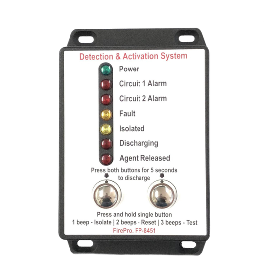
Control Panel Indicators & Operation LED Indicators The FP-08451 Control Panel uses LED indicators to notify the operator of the condition of the control panel and each of the monitored circuits. If an LED is illuminated, it indicates the... - Page 13 Fire Detection and Activation System Model 08451 Rev 3.1 isolated, any change in the detector status, will cause the panel sounder to operate for 1 second as an alert of the status change, but the panel will remain isolated. The isolate function will also silence the siren/strobe and the internal sounder but will not cancel the alarm or fault indication.
-
Page 14: Commissioning And Test Procedure
Note: No personnel should be in the risk area until the fire system is fully isolated. To ensure that the FirePro system will operate as designed, it should be inspected and serviced every 6 months, and yearly, in accordance with AS1851 and AS5062. - Page 15 Test backup battery capacity. Replace every backup battery every 2 years. • Disconnect the FP-08800 Test Module and reconnect all FirePro aerosol generators. • Turn off the Isolation function. System is now operational.
-
Page 16: Servicing And Maintenance
Fire Detection and Activation System Model 08451 Rev 3.1 Servicing and Maintenance Inspection and servicing of the installed fire system should occur in accordance with the relevant Australian Standards (i.e. AS1851 or AS5062). Any alterations to the risk area should be recorded and where necessary the risk assessment, design calculation and installed components must be revised to reflect the new operating conditions. -
Page 17: Troubleshooting
Rev 3.1 Troubleshooting The FP-08451 Control Panel provides a comprehensive fault monitoring system that will detect any open-circuit in the Circuit 1 Alarm Output, Circuit 2 Alarm Output, Siren/Strobe Output, Discharge Output and Agent Released Input and any malfunctions of the control panel’s internal components. -
Page 18: Rfi Environments
Cables should be installed with appropriate clearances from any cables or equipment that may produce high levels of RF interference. Safety Data Sheet (SDS) - FirePro This is an EXTRACT ONLY from the full SDS. To view the full SDS go to www.chemwatch.com.au. -
Page 19: Vehicle And Mobile Plant Installation Notes (As5062)
Fire Detection and Activation System Model 08451 Rev 3.1 Vehicle and Mobile Plant Installation Notes (AS5062) For AS5062 vehicle installations, a risk assessment must be completed all equipment, and the design agreed upon by the installer and operators. The risk assessment should include identification of all fuel and ignition sources, and these must be considered in the system design. -
Page 20: Specifications
4 at 24vDC Standard Discharge Delay 5 seconds from automatic/manual activation Max Discharge Delay Modules 2 DDM’s at 12vDC 4 DDM’s at 24vDC Max FirePro units using DDM’s 6 at 12vDC 20 at 24vDC Siren/Strobe Output Siren/Strobe Output Current Max 0.5A 0.5A poly-switch resettable fuse...
Need help?
Do you have a question about the 08451 and is the answer not in the manual?
Questions and answers