
Subscribe to Our Youtube Channel
Related Manuals for BCM Advanced Research ECM-3455J


Summary of Contents for BCM Advanced Research ECM-3455J
- Page 1 ECM-3455J User’s Manual ECM-3455J Intel® J3455 SoC 3.5 Inch Single Board Computer (SBC) User’s Manual Edition 1.00 – Aug, 2021...
- Page 2 Copyright Notice Copyright 2021 BCM Advanced Research, ALL RIGHTS RESERVED. No part of this document may be reproduced, copied, translated, or transmitted in any form or by any means, electronic or mechanical, for any purpose, without the prior written permission of the original manufacturer.
- Page 3 ECM-3455J User’s Manual Disclaimer BCM Advanced Research reserves the right to make changes, without notice, to any product, including circuits and/or software described or contained in this manual in order to improve design and/or performance. BCM Advanced Research assumes no responsibility or liability for the use of the described...
- Page 4 ECM-3455J User’s Manual A Message to the Customer BCM Customer Services Each and every BCM product is built to the most exacting specifications to ensure reliable performance in the harsh and demanding conditions typical of industrial environments. Whether your new BCM device is destined for the laboratory or the factory floor, you can be assured that your product will provide the reliability and ease of operation for which the name BCM has come to be known.
- Page 5 ECM-3455J User’s Manual Product Warranty BCM warrants to you, the original purchaser, that each of its products will be free from defects in materials and workmanship for two years from the date of purchase. This warranty does not apply to any products which have been repaired or altered by persons other than repair personnel authorized by BCM, or which have been subject to misuse, abuse, accident or improper installation.
- Page 6 ECM-3455J User’s Manual Manual Objectives This manual describes in detail the BCM ECM-3455J Main board. We strongly recommend that you study this manual carefully before attempting to interface with this mainboard or change the standard configurations. Whilst all the necessary information is available in this manual we would recommend that unless you are confident, you contact your supplier for guidance.
-
Page 7: Table Of Contents
ECM-3455J User’s Manual Contents Chapter 1: System Setup ....................Welcome! ..........................14 Packing Contents ........................14 Before you proceed ........................ 15 Mainboard Overview....................... 16 1.4.1 Mounting Holes ........................16 1.4.2 Onboard LEDs ........................17 1.4.3 Mainboard Layout (Top View/ Bottom View) ................18 1.4.4... - Page 8 ECM-3455J User’s Manual 1.7.14 SPI Header: SPI ........................34 1.7.15 SMBUS Header: SMBUS ....................... 34 1.7.16 Volume Control Header: VOLUME_CONTROL ..............35 1.7.17 LPT/ GPIO Header: LPT_GPIO ..................... 35 1.7.18 LPC Header: LPC ........................36 1.7.19 Speaker Header: SPEAKER ....................36 1.7.20...
- Page 9 ECM-3455J User’s Manual 3.7.9 XDCI Support ......................... 50 3.7.10 Realtek PCIe GBE Family Controller (MAC Address) ............50 3.7.11 Realtek PCIe GBE Family Controller (MAC Address) ............50 3.7.12 Trusted Computing ......................... 51 3.7.13 NCT6126D Super IO Configuration ..................52 3.7.13.1...
- Page 10 ......................69 Windows 10 Drivers Installation ..................... 69 Boot Mode ..........................69 Video Support ......................... 70 OTG Support .......................... 70 eDP Support (Available with ECM-3455J eDP version ONLY) ..........70 PXE Boot ..........................71 4.6.1 In "UEFI" mode: ........................71 4.6.2 In "Legacy"...
- Page 11 ECM-3455J User’s Manual Mainboard Specifications Model MX310H Processor/ Chipset Intel® J3455 SoC (1.5GHz Base Frequency, 2.3GHz Burst Frequency) One 204-pin SODIMM DDR3L-1600Mhz (PC3-12800) slot supports up to 8GB Max Memory Display Intel® Integrated HD Graphic Engine Maximum Resolution HDMI: 3840 x 2160 @ 30Hz...
- Page 12 ECM-3455J User’s Manual 1 x TPM 2.0 Security Device (Infineon® SLB9665TT-2.0) Onboard I/O Headers SATA 1 x Std. SATA III Connector 1 x SATA Power Header MSATA_MPCIE Supports mSATA SSDs M2_E Supports E-Key WIFI modules3 (Supports WIFI Cards in 2230 Only)
- Page 13 ECM-3455J User’s Manual Power & Connector 1 x Wide Range DC-In (9V~36V, 6A Max. 19V Recommended) 1x Header (uses a 1x4 2.54mm to AC adapter barrel connector cable) Form Factor 3.5” SBC (5.7” x 4”)
-
Page 14: Chapter 1: System Setup
ECM-3455J User’s Manual Chapter 1: System Setup This chapter describes the mainboard features and the new technologies it supports 1.1 Welcome! The mainboard delivers a host of new features and latest technologies, making it another line of BCM long life mainboards! Before you start installing the mainboard, and hardware devices on it, check the items in your package with the list below. -
Page 15: Before You Proceed
ECM-3455J User’s Manual Before you proceed Take note of the following precautions before you install mainboard components or change any mainboard settings. • Unplug the power cord from the wall socket before touching any component inside the system. • Use a grounded wrist strap or touch a safely grounded object or to a metal object, such as the power supply case, before handling components to avoid damaging them due to static electricity. -
Page 16: Mainboard Overview
ECM-3455J User’s Manual Mainboard Overview Before you install the mainboard, study the configuration of your chassis to ensure that the mainboard fits into it. Make sure to unplug the power cord before installing or removing the mainboard. Failure to do so can cause you physical injury and damage mainboard components. -
Page 17: Onboard Leds
ECM-3455J User’s Manual 1.4.2 Onboard LEDs The mainboard comes with a “Power On LED” (red) and one “Standby Power LED” (green) to indicate the system status. When the “Standby Power LED” lights on: It means the system is either in the standby state, or the power cable is still connected to the power source. The “Power On LED”... -
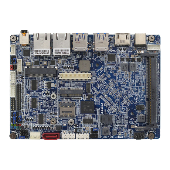
Page 18: Mainboard Layout (Top View/ Bottom View)
ECM-3455J User’s Manual 1.4.3 Mainboard Layout (Top View) -
Page 19: Layout Content List
ECM-3455J User’s Manual 1.4.4 Layout Content List • 1.4.4.1 Slots Label Function Note Page SODIMM_1 204-pin DDR3L SODIMM slot 8MB maximum MSATA_MPCIE Supports mSATA SSDs U_SIM Supports uSIM card M2_E Supports E-Key WIFI modules3 Supports WIFI Cards (E-key) in 2230 Only •... -
Page 20: Internal Headers
ECM-3455J User’s Manual • 1.4.4.3 Internal Headers Label Function Note Page DCIN_PWR 4-Pin Power Connector 1 x 4 shroud header, 2.54mm 9V~36V, 6A Max (19V recommended) F_PANEL System Panel Connector 2 x 5 header, pitch 2.54mm SYS_FAN System Fan Connector 1 x 4 wafer, Pitch 2.54mm... -
Page 21: Back Panel Connectors
ECM-3455J User’s Manual SPI Connector 2 x 4 header, 2.00mm SMBUS SMBUS Connector 1 x 3 header, 2.54mm VOLUME_CONTROL Volume Control 1 x 3 header, 2.54mm LPT_GPIO LPT/ GPIO Header 1 x 13 header, 2.00mm LPC Header 2 x 6 header, 2.00mm... -
Page 22: System Memroy
ECM-3455J User’s Manual System Memory 1.5.1 Overview The mainboard comes with one 204-pin DDR3L SODIMM socket. The following figure illustrates the location of the sockets:... -
Page 23: Memory Configurations
ECM-3455J User’s Manual 1.5.2 Memory Configurations The ECM-3455J board supports Non-ECC, Un-buffered, 204-pins DDR3L-1600MHz (PC3-12800) SODIMM up to 8GB Max. 1.5.3 Installing the DDR3L SODIMM Make sure to unplug the power supply before installing or removing SODIMMs, or other peripherals from the system. Failure to do so may cause severe damage to both the mainboard and the peripherals. -
Page 24: Removing The Ddr4 Sodimm
ECM-3455J User’s Manual NOTE: 1. A DDR3L memory module is keyed with a notch so that it fits in only one direction. 2. DO NOT force the memory module into the socket in order to avoid damaging the memory module and the slot. -
Page 25: Back Panel (Rear I/O Ports)
2. Under Legacy boot mode: Only either HDMI (default) or LVDS provides video signal. (if LVDS panel is attached, please disconnect the HDMI monitor connection to ECM-3455J board in order for the video signal to be switched to the LVDS panel). R_USB30_2 USB3.0 Ports The USB3.0 Port Connectors. - Page 26 ECM-3455J User’s Manual Blinking Data Orange 1Gbps activity connection LAN2 Gigabit LAN This port allows Gigabit connection to a Local Area Network (LAN) (RJ-45) Connectors through a network hub. Refer to the table below for the LAN port LED indications.
-
Page 27: Connectors/Headers
4-Pins Power Connector: DCIN_PWR This header is an alternative power connection for the system chassis which doesn’t provide the access to “DC_PWR” AC adapter connection through ECM-3455J rear IO. A 4-pin (2.54mm) to AC adapter barrel connector cable is required. -
Page 28: Front Panel Connector: F_Panel
ECM-3455J User’s Manual 1.7.2 Front Panel Connector: F_PANEL These connectors are for electrical connections to the front panel switches and LEDs. The “F_PANEL” connector is compliant with Intel® Front Panel I/O Connectivity Design Guide. 1.7.3 System Fan Connector: SYS_FAN The fan power connectors support system cooling fan with +12V. When connecting the wire to fan connector, please note that the red wire is designated as “Power”... -
Page 29: Seriall Ata 3.0 Connector: Sata3
ECM-3455J User’s Manual 1.7.4 Serial ATA 3.0 Connector: SATA3 This SATA port supports SATA3.0 standard. Do not fold the Serial ATA cable into 90-degree angle. Otherwise, data loss may occur during data transmission. 1.7.5 SATA Power Connector: SATA_PWR The SATA hard drive power connection. -
Page 30: Msata/ Mini-Pcie Connector: Msata_Mpcie
ECM-3455J User’s Manual 1.7.6 mSATA/ Mini-PCIE Connector: MSATA_MPCIE This connector supports mSATA type SSDs. 1.7.7 uSIM Card Slot: U_SIM This slot provides connection to uSIM card. -
Page 31: Socket: M2_E (E-Key, Supporrts Wifi Cards In 2230 Only)
ECM-3455J User’s Manual 1.7.8 M.2 Socket: M2_E (E-Key, Supports Wifi Cards in 2230 Only) This connector supports WIFI cards in 2230. 1.7.9 Front USB2.0 Headers: F_USB1, F_USB2 This header provides two USB2.0 connections (An USB2.0 cable is required). NOTE: 1. “F_USB2” header port 0 (the USB set on pin 2, 4, 6, 8, 10 only) Supports OTG when... -
Page 32: Com Ports: Coma, Comb
ECM-3455J User’s Manual 1.7.10 COM Ports: COMA, COMB These headers provide serial connections with serial port COMA and COMB. COMA provides RS232 or Ring-In support. COMB supports RS232/ RS422/ RS485, or Ring-In. 1.7.11 LVDS Panel Connector: LVDS This header provides connection to LVDS type panels in18/ 24-bit Single/ Dual channels. -
Page 33: Lvds Panel Backlight Connector: Backlight
ECM-3455J User’s Manual 1.7.12 LVDS Panel Backlight Connector: BACKLIGHT This header provides connection for LVDS panel backlight control connections. 1.7.13 I2C Header: I2C This header provides I2C signal connection. -
Page 34: Spi Header: Spi
ECM-3455J User’s Manual 1.7.14 SPI Header: SPI This header provides SPI signal connection. 1.7.15 SMBUS Header: SMBUS This header provides SMBUS signal connections. -
Page 35: Volume Control Header: Volume_Control
ECM-3455J User’s Manual 1.7.16 Volume Control Header: VOLUME_CONTROL This header provides volume control signal. 1.7.17 LPT/ GPIO Header: LPT_GPIO This header provides LPT or GPIO signal connections. -
Page 36: Lpc Header: Lpc
ECM-3455J User’s Manual 1.7.18 LPC Header: LPC This header provides LPC signal connections. 1.7.19 Speaker Header: SPEAKER This header supports 4 ohms/ 2W speaker. -
Page 37: Chassis Intrusion Header: Ci
ECM-3455J User’s Manual 1.7.20 Chassis Intrusion Header: CI This 2-pins header provides chassis intrusion warning connection. -
Page 38: Jumpers
ECM-3455J User’s Manual Jumpers 1.8.1 ATX/AT Mode Select: AT_ATX This header provides the option to boot the system in the form of ATX mode (default) or AT mode. When the system is set in AT mode, the system power on/off will be controlled directly by the power switch on the power supply. -
Page 39: Com Port +12V/ +5V/ Ring-In Select: Coma_Pw, Comb_Pw
ECM-3455J User’s Manual 1.8.3 COM Port +12V/ +5V/ Ring-In Select: COMA_PW, COMB_PW These jumpers provide selection between +12V, +5V, and Ring-In (default). 1.8.4 GPIO High/ Low Select: GPIO_SET This jumper provides selection for GPIO High (+3V, default) or Low. -
Page 40: Lpt/ Gpio Selection For Header "Lpt_Gpio": Lpt_Sel
ECM-3455J User’s Manual 1.8.5 LPT/ GPIO Selection for header “LPT_GPIO”: LPT_SEL This jumper selects will designate the function of “LPT_GPIO” header in “LPT” or “GPIO”. 1.8.6 GPIO Power Select: GPIO_PWRSEL When “LPT_GPIO” header is set in GPIO mode, this jumper selects its pin #10, 12 “GPIOPWR”... -
Page 41: Clear Cmos Header: Clr_Cmos
For normal state (default), the jumper is set on pin location 2 and 3. To clear the CMOS, here is the procedure: 1. Disconnect all power connections to ECM-3455J first, 2. Set the “CLR_CMOS” jumper to pin location 1 and 2 for at least 30 seconds while the system is disconnected from the power. -
Page 42: Chapter 2: Starting Up The System
ECM-3455J User’s Manual Chapter 2: Starting Up the System Starting Up Your System 1. After all connections are made, close your computer case cover. 2. Be sure all the switches are off, and check that the power supply input voltage is set to the local voltage, usually in-put voltage is 220V240V or 110V120V depending on your country’s... - Page 43 ECM-3455J User’s Manual NOTE: During system power-on (system post), press <Del> key to enter BIOS setup. Follow the instructions in BIOS SETUP. If you wish to boot from a different bootable device other than the default arrangement under the BIOS, you may press <F11>...
-
Page 44: Chapter 3: Bios Setup
ECM-3455J User’s Manual Chapter 3: BIOS Setup 3.1 BIOS Flash Related Procedure 1. After the BIOS is flashed, shut down the system. 2. Disconnect all power connections from power supply to the mainboard. 3. Clear the CMOS (For at least 30 seconds). -
Page 45: Entering Bios Setup Menu
ECM-3455J User’s Manual 3.3 Entering BIOS Setup Menu Power on the computer and by pressing <DEL> immediately allows you to enter BIOS Setup Menu. If you are not able to enter the BIOS menu but you still wish to enter Setup, restart the system to try again by turning it OFF then ON or pressing the “RESET”... -
Page 46: Getting Help
ECM-3455J User’s Manual 3.4 Getting Help Main Menu The main menu lists the setup functions you can make changes to. You can use the arrow keys to select the item. The on-line description of the highlighted setup function is displayed at the bottom of the screen. -
Page 47: Bios Menu Screen
ECM-3455J User’s Manual 3.5 BIOS Menu Screen When entering the BIOS, the following screen appears. The BIOS menu screen displays the items that allow user to make changes to the system configuration. To access the menu items, press the up/down/right/left arrow key on the keyboard until the desired item is highlighted, then press [Enter]... -
Page 48: Main Menu
ECM-3455J User’s Manual 3.6 Main Menu This menu gives user an overview of the general system specifications, such as time, date etc. 3.6.1 System Information Displays the auto-detected BIOS information. 3.6.2 System Date The date format is in <Day>,<Month>,<Year>. 3.6.3 System Time... -
Page 49: Advanced Menu
ECM-3455J User’s Manual 3.7 Advanced Menu Select the “Advanced” tab from the BIOS menu screen to enter the Advanced BIOS Setup screen. NOTE: Take caution when change the settings of the Advanced menu items. Incorrect field setting could cause the system not to function properly. -
Page 50: Watch Dog
ECM-3455J User’s Manual 3.7.2 Watch Dog Enable/ Disable Watch Dog Timer. 3.7.3 Onboard LAN Controller Enable/ Disable onboard LAN Controller#1 (The one next to the USB3.0 ports). 3.7.4 Onboard LAN Controller#2 Enable/ Disable onboard LAN Controller#2 (The one next to the audio port). -
Page 51: Trusted Computing
ECM-3455J User’s Manual 3.7.12 Trusted Computing Trusted Computing Settings. NOTE: When “TPM Support” is enabled, it requires to save and exit BIOS once. And reboot the system in order to initiate the TPM support at BIOS. CAUTION: When TPM is enabled and utilized through TPM software under OS, there is a... -
Page 52: Nct6126D Super Io Configuration
ECM-3455J User’s Manual 3.7.13 NCT6126D Super IO Configuration System Super IO chip parameters. 3.7.13.1 Serial port 1 Configuration Set parameters of Serial Port 1 (“COMA” header). 3.7.13.2 Serial port 2 Configuration Set parameters of Serial Port 2 (“COMB” header). 3.7.13.3 Parallel port Configuration Set parameters of parallel Port (“LPT”... -
Page 53: Hardware Monitor
ECM-3455J User’s Manual 3.7.14 Hardware Monitor Monitor hardware status. -
Page 54: Smart Fan Function
ECM-3455J User’s Manual 3.7.14.1 Smart Fan Function Smart Fan setting for system fan header “SYS_FAN”. 3.7.14.1.1 System Fan Mode: Manual Mode Step up time: The amount of time fan takes to increase its value by one step. (Units are intervals of 0.1 second). -
Page 55: System Fan Mode: Thermal Cruise
ECM-3455J User’s Manual 3.7.14.1.2 System Fan Mode: Thermal Cruise Step up time: The amount of time fan takes to increase its value by one step. (Units are intervals of 0.1 second). 10 x 0.1 sec = 1 sec as default. - Page 56 ECM-3455J User’s Manual Three conditions may occur: If the temperature still exceeds the high end, fan output increases slowly. If the fan is operating at full speed but the temperature still exceeds the high end, a warning message is issued to protect the system.
-
Page 57: Cpu Configuration
ECM-3455J User’s Manual 3.7.15 CPU Configuration CPU Configuration Parameters. 3.7.15.1 Socket 0 CPU Information Socket specific CPU information. 3.7.15.2 CPU Power Management CPU Power Management options. 3.7.15.2.1 EIST Enable/ Disable Intel Speedstep. 3.7.15.2.2 Turbo Mode Tubo mode enable/ disable. -
Page 58: C-State
ECM-3455J User’s Manual 3.7.15.2.3 C-States Enable/ disable C states. 3.7.15.2.4 Enhanced C-States Enable/ disable C1E. When enabled, CPU will switch to minimum speed when all cores enter C-State. 3.7.15.3 Active Processor Cores Number of cores to enable in each processor package. -
Page 59: Usb Configuration
ECM-3455J User’s Manual 3.7.16 USB Configuration USB Configuration parameters. 3.7.16.1 Onboard USB Feature USB Support parameters. 3.7.16.2 Legacy USB Support Enable Legacy USB support. Auto option disables legacy support if no USB devices are connected. Disable option will keep USB devices available only for EFI applications. -
Page 60: Usb Mass Storage Driver Support
ECM-3455J User’s Manual 3.7.16.4 USB Mass Storage Driver Support Enable/ disable USB Mass Storage Driver Support. -
Page 61: Network Stack Configuration
ECM-3455J User’s Manual 3.7.17 Network Stack Configuration Network Stack Settings. 3.7.17.1 Network Stack Enable/ disable UEFI Network Stack. 3.7.17.2 Ipv4 PXE Support Enable Ipv4 PXE Boot Support. If disabled IPV4 PXE boot option will not be created. 3.7.17.3 Ipv4 HTTP Support Enable Ipv4 HTTP Boot Support. -
Page 62: Ipv6 Http Support
ECM-3455J User’s Manual 3.7.17.5 Ipv6 HTTP Support Enable Ipv6 HTTP Boot Support. If disabled IPV6 HTTP option will not be created. 3.7.17.6 PXE boot wait time Wait time too press ESC key to abort the PXE boot. 3.7.17.7 Media detect count Number of times presence of media will be checked. -
Page 63: Security Menu
ECM-3455J User’s Manual 3.8 Security Menu Set setup administrator/ user password or secure boot related settings. 3.8.1 Setup Administrator Password Setup Administrator Password. If only the administrator’s password is set, then this only limits access to BIOS menu and is only asked for when entering BIOS. -
Page 64: Secure Boot
ECM-3455J User’s Manual 3.8.3 Secure Boot Customizable Secure Boot settings. Customer needs to provide the code to the board manufacture in order to insert the code to the BIOS. Customer also needs to embedded the corresponding key in their OS image. -
Page 65: Boot Menu
ECM-3455J User’s Manual 3.9 Boot Menu Set the system boot order. 3.9.1 Setup Prompt Timeout Number of second to wait for setup activation key. 3.9.2 Bootup NumLock State Select the keyboard NumLock state. 3.9.3 Full Screen LOGO Show Enable or disables Quiet Boot option. -
Page 66: Boot Mode Select
ECM-3455J User’s Manual 3.9.5 Boot mode select Select boot mode in Legacy or UEFI (default). NOTE: If user needs to switch the boot mode between UEFI and Legacy; then user needs to select the desired boot mode first, then save and exit BIOS. The system needs to reboot once in order for the selected boot mode to take effect. -
Page 67: Save & Exit Menu
ECM-3455J User’s Manual 3.10 Save & Exit Save and Exit BIOS settings. 3.10.1 Save Changes and Exit Exit system setup after saving the changes. 3.10.2 Discard Changes and Exit Exit BIOS without saving any changes made. 3.10.3 Load Optimized Defaults Automatically load optimal BIOS settings. -
Page 68: Boot Override
ECM-3455J User’s Manual 3.10.4 Boot Override Choose the desired boot device to be the first boot device at next reboot. NOTE: This function will only function once after rebooted. If user prefers to set the boot device boot order permanently, then the change will need to be made under “Boot”-> “Fixed Boot Order Priorties”... -
Page 69: Chapter 4: Application Note
Please read the following application notes before proceed with the system setup and/or OS installation: Windows 10 Drivers Installation It is recommended to load the ECM-3455J drivers with following sequence: 1. Install “Intel INF Driver”. 2. Install “Intel Video Driver”. -
Page 70: Video Support
2. Under Legacy boot mode: Only either HDMI (default) or LVDS provides video signal. (if LVDS panel is attached, please disconnect the HDMI monitor connection to ECM-3455J board in order for the video signal to be switched to the LVDS panel). -
Page 71: Pxe Boot
ECM-3455J User’s Manual PXE Boot 4.6.1 In “UEFI” mode: 1. Under BIOS option “Boot”->”Boot mode select”; change it to “UEFI”. 2. Under BIOS option “Advance”->”Network Stack Configuration”: a. Change “Network Stack” to “Enabled”. b. Enable “Ipv4 PXE Support”. 3. Save and exit BIOS. -
Page 72: In "Legacy" Mode
Here is the installation procedure for MIC support under Win10 environment: 1. Install BCM provided ECM-3455J specific Realtek Win10 audio driver. 2. When the headset is plug-in to ECM-3455J rear audio port; the system will be prompted for the selection of “Headset” or “Headphone”, Please select “Headset” ONLY.
Need help?
Do you have a question about the ECM-3455J and is the answer not in the manual?
Questions and answers