
Related Manuals for BCM Advanced Research RX110H


Summary of Contents for BCM Advanced Research RX110H
- Page 1 RX110H Intel® Sky Lake (6 gen i7/i5/i3)/ Kaby Lake (7 gen i7/i5/i3) Micro-ATX Mainboard BCM P/N: 71172 ONLY User’s Manual Edition 1.00 – Feb, 2017...
- Page 2 Copyright Notice Copyright © 2017 BCM Advanced Research, ALL RIGHTS RESERVED. No part of this document may be reproduced, copied, translated, or transmitted in any form or by any means, electronic or mechanical, for any purpose, without the prior written permission of the original manufacturer.
- Page 3 Disclaimer BCM Advanced Research reserves the right to make changes, without notice, to any product, including circuits and/or software described or contained in this manual in order to improve design and/or performance. BCM Advanced Research assumes no responsibility or liability for the use of the described...
-
Page 4: Bcm Customer Services
In addition, free technical support is available from BCM engineers every business day. We are always ready to give advice on application requirements or specific information on the installation and operation of any of our products. Please do not hesitate to call or e-mail us. BCM Advanced Research 11 Chrysler, Irvine, California, 92618... -
Page 5: Product Warranty
Product Warranty BCM warrants to you, the original purchaser, that each of its products will be free from defects in materials and workmanship for two years from the date of purchase. This warranty does not apply to any products which have been repaired or altered by persons other than repair personnel authorized by BCM, or which have been subject to misuse, abuse, accident or improper installation. - Page 6 Manual Objectives This manual describes in detail the BCM RX110H mainboard. We strongly recommend that you study this manual carefully before attempting to interface with the motherboard or change the standard configurations. Whilst all the necessary information is available in this manual we would recommend that unless you are confident, you contact your supplier for guidance.
-
Page 7: Table Of Contents
Contents Chapter 1: System Setup ....................Welcome! ............................12 Packing Contents ........................... 12 Special Features ..........................13 1.3.1 Product Highlights .......................... 13 Before you proceed ........................14 Mainboard Overview ........................15 1.5.1 Mounting Holes ..........................15 1.5.2 Onboard LEDs ..........................16 1.5.3 Mainboard Layout ........................... - Page 8 COM6 ............................. 32 1.9.10 LPT Port Header: LPT1 ........................32 1.9.11 3W Audio AMP Output: SPEAKER1 ....................33 1.9.12 Front Panel Audio Header: HD_AUDIO1 ..................34 1.10 Jumpers ............................35 1.10.1 COM1 Pin#9 Power Setting Jumper: PWR_COM1 ................ 35 1.10.2 Rear I/O USB Ports Power Setting Jumpers: USB2_PWR1 (For USB2.0 Port "USB2_89"), USB3_PWR1 (For USB3.0 Port "USB3_45") .................
- Page 9 3.6.6 USB Configuration .......................... 59 3.6.7 Trusted Computing ......................... 60 Hardware Health Event Monitoring Screen ..................61 Security Screen ..........................63 Boot Screen ............................ 64 3.9.1 CSM (Compatibility Support Module) ..................... 65 3.10 Exit Screen ............................. 67 Chapter 4: Application Note ..................
- Page 10 Mainboard Specifications Model RX110H Processor Intel® 6th Generation LGA1151 core i3, Core i5, Core i7 (Sky Lake) Intel® 7th Generation LGA1151 core i3, Core i5, Core i7 (Kaby Lake) Note: BCM P/N: 71172 ONLY Chipset Intel® H110 2 x 288Pin DIMM sockets support Non-ECC, Un-buffered DDR4 memory module...
- Page 11 RS232 5 x Headers 1 x Header Front Audio 1 x Header Amplifier 1 x Header Front Panel 1 x Header Fan Header 3 x Headers (4-pins) GPIO 1 x Header Onboard Jumpers COM Port Ring-In/ Power Select 5 x Headers provide selection of “Ring-In”, or “12V” or “5V” on RS232 COM port AT/ATX Select 1 x Header Clear CMOS...
-
Page 12: Chapter 1: System Setup
If any of the items listed below is damaged of missing, please contact with your vendor. 1.2 Packing Contents • Mainboard • 1 x RX110H • Cable • 2 x SATA Power Cable • Accessories • 1 x RX110H I/O Shield... -
Page 13: Special Features
1.3 Special Features 1.3.1 Product Highlights • The 6 Generation Intel® i7/i5/i3 LGA1151 Processor Support (BCM P/N: 71172 ONLY) This mainboard supports the 6th generation Intel® i7/i5/i3 processors (Sky Lake) & 7 generation Intel® i7/i5/i3 processors (Kaby Lake) in the LGA1151 package. •... -
Page 14: Before You Proceed
1.4 Before you proceed Take note of the following precautions before you install mainboard components or change any mainboard settings. • Unplug the power cord from the wall socket before touching any component inside the system. • Use a grounded wrist strap or touch a safely grounded object or to a metal object, such as the power supply case, before handling components to avoid damaging them due to static electricity. -
Page 15: Mainboard Overview
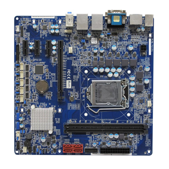
1.5 Mainboard Overview Before you install the mainboard, study the configuration of your chassis to ensure that the mainboard fits into it. Make sure to unplug the power cord before installing or removing the mainboard. Failure to do so can cause you physical injury and damage mainboard components. 1.5.1 Mounting Holes Place the screws into the mounting holes indicated by red circles (shown in the picture below) to secure the... -
Page 16: Onboard Leds
1.5.2 Onboard LEDs The mainboard comes with a “Power On LED” (green) and one “Standby Power LED” (red) to indicate the system status. When the “Standby Power LED” lights on: It means the system is either in the standby state, or the power cable is still connected to the power source. -
Page 17: Mainboard Layout
1.5.3 Mainboard Layout... -
Page 18: Layout Content List
1.5.4 Layout Content List • 1.5.4.1 Slots Label Function Note Page DDR4_A1 288-pin DDR4 DIMM slot A1 1. If there is only one memory module being installed in the system, install it on this slot. DDR4_B1 288-pin DDR4 DIMM slot B1 PCIE1 PCI Express x16 slot PCIE2... -
Page 19: Internal Headers
JGPIO_PWR1 GPIO Input/ Output Power Select: 3 x 1 header, pitch 2.54mm +5V (default) / +12V JGPIO_SET1 GPIO Signals Pull-High/ Pull-Low 3 x 1 header, pitch 2.54mm Select: Pull-High to +3V (default)/ Pull-Low to Ground PWR_COM2, COM2/3/4/5/6 Pin#9 Power Setting 3 x 2 header, pitch 2.54mm PWR_COM3, Jumper: RI (default)/ +5V/ +12V... -
Page 20: Back Panel Connectors
LPT1 LPT Port Header 13 x 2 wafer, pitch 2.00mm SPEAKER1 3W Audio AMP Output 4 x 1 wafer, pitch 2.00mm HD_AUDIO1 Front Panel Audio Header 5 x 2 header, pitch 2.54mm • 1.5.4.4 Back Panel Connectors Label Function Note Page PS2_KBMS1 PS/2 Mouse Connector... -
Page 21: System Memroy
System Memory 1.6.1 Overview The mainboard provides two 288-pin DDR4 (Double Data Rate 4) DIMM slots, and supports Dual Channel Memory Technology. 1.6.2 Memory Configurations You may ONLY install 288-pin Non-ECC, Un-buffered DDR4 memory module (PC4-17000) 2133 MHz up to 32GB (16GB maximum/slot) on this board. •... -
Page 22: Installing The Ddr4 Dimm
1.6.3 Installing the DDR4 DIMM Make sure to unplug the power supply before adding or removing DIMMs or other peripherals from the system. Failure to do so may cause severe damage to both the mainboard and the peripherals. 1. Unlock a DIMM socket by pressing the retaining clips outward. 2. -
Page 23: Removing The Ddr4 Dimm
1. A DDR4 memory module is keyed with a notch so that it fits in only one direction. 2. DO NOT force the memory module into the socket in order to avoid damage the memory module and the slot. 3. DDR4 memory modules are not interchangeable with DDR, DDR2, or DDR3. 4. -
Page 24: Power Supply
1.7 Power Supply 1.7.1 ATX Power Connectors: ATXPWR1, ATX12V1 These ATX power connectors provide connections from power supply unit (PSU) to the mainboard. Both connectors need to be installed in order for the mainboard to function properly. The power supply plugs are designed to fit with these ATX power connectors in one orientation only. To connect these power supply plugs;... -
Page 25: Back Panel
Back Panel 1.8.1 Back Panel Connectors Item Name Function Description PS2_KBMS1 PS/2 Mouse PS/2 Mouse Connection. Connector Display Port This port provides Display Port connection. COM1 Serial COM This port provides serial port connection. Port 1 (RS232 (default), RS422, RS485 Selection available under BIOS) LAN1/ LAN2 Gigabit LAN... - Page 26 AUDIO Line-out port This port connects a headphone or a speaker. (Green) AUDIO Microphone This port connects a microphone. port (Pink) USB3_45 USB 3.0 These two Universal Serial Bus (USB) ports Connectors are available for connecting USB 3.0 devices. USB2_89 USB 2.0 These two 4-pin Universal Serial Bus (USB) Connectors...
-
Page 27: Connectors/Headers
Connectors/ Headers 1.9.1 USB3.0 Header: USB3_3_4 The internal USB3.0 header (Provides two USB3.0 ports). 1.9.2 Serial ATA 3.0 Connectors: SATA3_1, SATA3_2, SATA3_3, SATA3_4 SATA ports “SATA3_1”, “SATA3_2”, “SATA3_3”, “SATA3_4” support SATA3.0 standard. Please do not fold the Serial ATA cable into 90-degree angle, data loss may occur during data transmission. -
Page 28: Digital Input/ Output Header: Jgpio1
1.9.3 Digital Input/ Output Header: JGPIO1 This header provides 8-bit GPIO connections to external device. Customer can write the monitoring program to monitor the status of external device connected with this header. -
Page 29: Cpu & System Fan Connectors: Cpu_Fan1, Cha_Fan1, Cha_Fan2
1.9.4 CPU & System Fan Connectors: CPU_FAN1, CHA_FAN1, CHA_FAN2 The fan power connectors support system cooling fan with +12V. When connecting the wire to these fan connectors, please note that the red wire is designated as “Power” and should be connected to “+12V”... -
Page 30: External Buzzer Connector: Buzz2
1.9.5 External Buzzer Connector: BUZZ2 This header provides connection to external buzzer on chassis. 1.9.6 System Panel Header: PANEL1 This header provides front panel connections (Power button, Reset button, Power LED, HDD LED) on chassis. -
Page 31: Chassis Intrusion Headers: Ci1, Ci2
1.9.7 Chassis Intrusion Headers: CI1, CI2 Two chassis instruction headers, choose the one that matches with the chassis intrusion connection in the chassis. 1.9.8 USB2.0 Headers: USB2_0_1, USB2_2_3 Two internal USB2.0 headers (two USB2.0 ports/ header). -
Page 32: Com2, Com3, Com4, Com5, Com6 Headers (Rs232 Only): Com2, Com3, Com4, Com5
1.9.9 COM2, COM3, COM4, COM5, COM6 Headers (RS232 ONLY): COM2, COM3, COM4, COM5, COM6 The COM2, 3, 4, 5, 6 that provides RI in RS232 only. 1.9.10 LPT Port Header: LPT1 This header provides parallel port connection. -
Page 33: Audio Amp Output: Speaker1
1.9.11 3W Audio AMP Output: SPEAKER1 This header provides amplified speaker output (3W) for simple two external speaker connection. Its volume control is available under the BIOS. -
Page 34: Front Panel Audio Header: Hd_Audio1
1.9.12 Front Panel Audio Header: HD_AUDIO1 This connector is prepared for a chassis-mounted front panel audio I/O module that supports HD Audio standard. Connect one end of the front panel audio I/O module cable to this connector. -
Page 35: Jumpers
1.10 Jumpers 1.10.1 COM1 Pin#9 Power Setting Jumper: PWR_COM1 This header provides power selection for COM1 Pin#9. 1.10.2 Rear I/O USB Ports Power Setting Jumpers: USB2_PWR1 (For USB2.0 Port “USB2_89”), USB3_PWR1 (For USB3.0 Port “USB3_45”) This header provides power selection for rear I/O USB ports. -
Page 36: Usb Power Setting Jumper For Usb3.0 Header "Usb3_3_4": Usb3_Pwr2
1.10.3 USB Power Setting Jumper for USB3.0 Header “USB3_3_4”: USB3_PWR2 This header provides power selection for USB3.0 header “USB3_3_4”. 1.10.4 GPIO Input/ Output Power Select: JGPIO_PWR1 This header provides power selection for GPIO Input/Output. -
Page 37: Gpio Signals Pull-High/ Pull-Low Selection: Jgpio_Set1
1.10.5 GPIO Signals Pull-High/ Pull-Low Selection: JGPIO_SET1 This header provides Pull-High/Pull-Low selection for GPIO header. -
Page 38: Clear Cmos Header: Clrmos1
1.10.6 Clear CMOS Header: CLRMOS1 There is a CMOS RAM onboard that has the power supplied from an external battery to maintain the registry settings of system configuration. For normal state (default), the jumper is set on pin location 1 and 2. To clear the CMOS, disconnect all power connections to mainboard first, then set the CLRMOS1 jumper to pin location 2 and 3 for at least 30 seconds while the system is off, then place the jumper back to pin 1-2 for normal operation. -
Page 39: Usb Ports Power Settings Jumpers: Usb2_Pwr2 (For Usb2.0 Port "Usb2_0_1")
1.10.7 USB Ports Power Setting Jumpers: USB2_PWR2 (For USB2.0 Port “USB2_0_1”), USB2_PWR3 (For USB2.0 Port “USB2_2_3”) These headers provide power selection for USB2.0 headers “USB2_0_1” and “USB2_3_3”. 1.10.8 ATX/ AT Mode Select: PWR_JP1 This header provides the option to boot the system in the form of ATX mode (default) or AT mode. -
Page 40: Pwr_Com5, Pwr_Com6
1.10.9 COM2/3/4/5/6 Pin#9 Power Setting Jumper: PWR_COM2, PWR_COM3, PWR_COM4, PWR_COM5, PWR_COM6 This header provides power selection for COM2,3, 4, 5, 6 Pin#9. -
Page 41: The Expansion Slots
1.11 The Expansion Slots In the future, you may need to install expansion cards. The following sub-sections describe the expansion slots and the expansion cards that they support. Make sure to unplug the power cord before adding or removing expansion cards. Fail to do so may cause injury and damage mainboard. -
Page 42: Chapter 2: Starting Up The System
Chapter 2: Starting Up the System Starting Up Your System After all connections are made, close your computer case cover. Be sure all the switches are off, and check that the power supply input voltage is set to the local voltage, usually in-put voltage is 220V∼240V or 110V∼120V depending on your country’s voltage used. - Page 43 devices which are attached to the system will be displayed. Then you may select the desired first bootable device from this menu. Power off your computer: You must first exit or shut down your operating system before switch off the power switch. If you use Windows Operating Systems, click “Start” button, click “Shut down” and then click “Shut down the computer”...
-
Page 44: Chapter 3: Bios Setup
Chapter 3: BIOS Setup BIOS Flash Related Procedure 1. After the BIOS is flashed, shut down the system. 2. Disconnect all power connections from power supply to the mainboard. 3. Clear the CMOS by relocate the jumper connector on header “CLRMOS” from pin 1-2 to pin 2-3 for at least 30 seconds. -
Page 45: Entering Bios Setup Menu
• Press Page Up/Page Down or +/– keys when you want to modify the BIOS parameters for the active option. Entering BIOS Setup Menu Power on the computer and by pressing <DEL> immediately allows you to enter BIOS Setup Menu. If you are not able to enter the BIOS menu but you still wish to enter Setup, restart the system to try again by turning it OFF then ON or pressing the “RESET”... -
Page 46: Uefi Menu Bar
The BIOS setup program provides a General Help screen. You can call up this screen from any menu by simply pressing <F1>. The Help screen lists the appropriate keys to use and the possible selections for the highlighted item. Press <Esc> to exit the Help screen. 3.4.1 UEFI Menu Bar The top of the screen has a menu bar with the following selections: Main... -
Page 47: Main Screen
3.5 Main Screen When you enter the UEFI SETUP UTILITY, the Main screen will appear and display the system overview. -
Page 48: Advanced Screen
3.6 Advanced Screen In this section, you may set the configurations for the following items: CPU Configuration, Chipset Configuration, Storage Configuration, Super IO Configuration, ACPI Configuration, USB Configuration and Trusted Computing. Setting wrong values in this section may cause the system not function properly. -
Page 49: Cpu Configuration
3.6.1 CPU Configuration Active Processor Cores Use this item to select the number of cores to enable in each processor package. The default value is [All]. CPU C States Support Enable CPU C States Support for power saving. It is recommended to keep C3, C6 and C7 all enabled for better power saving. - Page 50 CPU C7 State Support Use this to enable or disable CPU C7 (ACPI C7) report to OS. Package C State Support Selected option will program into C State package limit register. The default value is [Auto]. Intel SpeedStep Technology Intel SpeedStep technology is Intel’s new power saving technology. Processors can switch between multiple frequencies and voltage points to enable power saving.
- Page 51 Intel Virtualization Technology When this option is set to [Enabled], a VMM (Virtual Machine Architecture) can utilize the additional hardware capabilities provided by Vanderpool Technology. This option will be hidden if the installed CPU does not support Intel Virtualization Technology. Hardware Prefetcher Use this item to turn on/off the MLC streamer prefetcher.
-
Page 52: Chipset Configuration
3.6.2 Chipset Configuration Primary Graphics Adapter This allows you to select [Onboard] or [PCI Express] as the boot graphic adapter priority. The default value is [PCI Express]. Top of Lower Usable Dram The default value is [Dynamic]. VT-d Use this to enable or disable Intel®... - Page 53 IGPU Multi-Moniter This allows you to enable or disable IGPU Multi-Moniter. The default value is [Enabled]. If you install the PCI Express card under Windows® XP / VistaTM OS, please disable this option. Onboard LAN 1 This allows you to enable or disable the Onboard LAN 1 feature. Onboard LAN 2 This allows you to enable or disable the Onboard LAN 2 feature.
-
Page 54: Storage Configuration
3.6.3 Storage Configuration SATA Controller(s) Use this item to enable or disable the SATA Controller feature. SATA Aggressive Link Power Management Use this item to configure SATA Aggressive Link Power Management. Hard Disk S.M.A.R.T. Use this item to enable or disable the S.M.A.R.T. (Self-Monitoring, Analysis, and Reporting Technology) feature. -
Page 55: Super Io Configuration
3.6.4 Super IO Configuration COM1 Configuration Use this to set parameters of COM1. Select COM1 port type: [RS232] (default), [RS422] or [RS485]. COM2 Configuration Use this to set parameters of COM2. COM3 Configuration Use this to set parameters of COM3. COM4 Configuration Use this to set parameters of COM4. - Page 56 Use this to set parameters of COM6. LPT1 Port Configuration Use this set parameters of the onboard parallel port. WDT Timeout Reset This allows users to enable/disable the Watch Dog Timer timeout to reset system. The default value is [Disabled].
-
Page 57: Acpi Configuration
3.6.5 ACPI Configuration Suspend to RAM Use this item to select whether to auto-detect or disable the Suspend-to-RAM feature. Select [Auto] will enable this feature if the installed OS supports it. ACPI HPET Table Use this item to enable or disable ACPI HPET Table. The default value is [Enabled]. Please set this option to [Enabled] if you plan to use this motherboard to submit Windows®... - Page 58 RTC Alarm Power On Use this item to enable or disable RTC (Real Time Clock) to power on the system.
-
Page 59: Usb Configuration
3.6.6 USB Configuration USB Controller Use this item to enable or disable the use of USB controller. Legacy USB Support Use this option to select legacy support for USB devices. There are four configuration options: [Enabled], [Auto] and [UEFI Setup Only]. The default value is [Auto]. Please refer to below descriptions for the details of these four options: [Enabled] - Enables support for legacy USB. -
Page 60: Trusted Computing
3.6.7 Trusted Computing Security Device Support Enable or disable BIOS support for security device. -
Page 61: Hardware Health Event Monitoring Screen
3.7 Hardware Health Event Monitoring Screen In this section, it allows you to monitor the status of the hardware on your system, including the parameters of the CPU temperature, motherboard temperature, CPU fan speed, chassis fan speed, and the critical voltage. - Page 62 Clear Status This option appears only when the case open has been detected. Use this option to keep or clear the record of previous chassis intrusion status.
-
Page 63: Security Screen
3.8 Security Screen In this section, you may set, change or clear the supervisor/user password for the system. Supervisor Password Set or change the password for the administrator account. Only the administrator has authority to change the settings in the UEFI Setup Utility. Leave it blank and press enter to remove the password. -
Page 64: Boot Screen
3.9 Boot Screen In this section, it will display the available devices on your system for you to configure the boot settings and the boot priority. Boot From Onboard LAN Use this item to enable or disable the Boot From Onboard LAN feature. Setup Prompt Timeout This shows the number of seconds to wait for setup activation key. -
Page 65: Csm (Compatibility Support Module)
3.9.1 CSM (Compatibility Support Module) Enable to launch the Compatibility Support Module. Please do not disable unless you’re running a WHCK test. If you are using Windows® 8 64-bit and all of your devices support UEFI, you may also disable CSM for faster boot speed. Launch PXE OpROM Policy Select UEFI only to run those that support UEFI option ROM only. - Page 66 that support legacy option ROM only. Select Do not launch to not execute both legacy and UEFI option ROM.
-
Page 67: Exit Screen
3.10 Exit Screen Reset System with ME disable Mode ME will run into the temporary disable mode. Ignore it if ME Ignition FW. Save Changes and Exit When you select this option, it will pop-out the following message, “Save configuration changes and exit setup?”... -
Page 68: Chapter 4: Application Note
Chapter 4: Application Note Please read the following application notes before proceed with the system setup and/or OS installation: None...
Need help?
Do you have a question about the RX110H and is the answer not in the manual?
Questions and answers