
Related Manuals for BCM Advanced Research MX110H


Summary of Contents for BCM Advanced Research MX110H
- Page 1 MX110H Ver 1.0 User’s Manual Intel® H110 Mini ITX Motherboard supports 14nm Intel® Core™ i7/i5/i3 generation Desktop Processors (Skylake Platform)
-
Page 2: Safety Information
Safety Information Electrical safety To prevent electrical shock hazard, disconnect the power cable from the electrical outlet before relocating the system. When adding or removing devices to or from the system, ensure that the power cables for the devices are unplugged before the signal cables are connected. If possible, disconnect all power cables from the existing system before you add a device. -
Page 3: Safety Declaration
If a problem arises with your system and no solution can be obtained from the user’s manual, please contact your place of purchase or local distributor. Alternatively, please try the following help resources for further guidance. Visit the BCM Advanced Research website: Revision History Revision ... -
Page 4: Table Of Contents
Contents 1 Introduction ............5 1.1 Package Contents ............5 1.2 Speci cations ..............6 1.3 Motherboard Layout ............9 1.4 I/O Panel ................ 11 2 Installation ............12 2.1 Screw Holes ..............12 2.2 Pre-installation Precautions ........... 12 2.3 Processor ............... 13 2.3.1 Installing the CPU .......... -
Page 5: Introduction
Chapter 1: Introduction Thank you for purchasing MX110H motherboard, a reliable motherboard produced under our consistently stringent quality control. It delivers excellent performance with robust design conforming to our commitment to quality and endurance. Because the motherboard specifications and the BIOS software might be updated, the content of this manual will be subject to change without no- tice. -
Page 6: Speci Cations
1.2 Specifi cations Model Name MX110H Mini-ITX 6.7 x 6.7 inches MB Dimension 8 Layer Board BCM Standard Blue All Solid CAP Fanless ATX PWR IN System ® Intel Skylake Processor Supports LGA 1151 Core i7, Core i5, Core i3, Celeron CPU Up to 65W Max ®... - Page 7 Internal I/O 1 x LVDS/eDP shared Header Display 1 x Backlight Locking Type Header 3 x SATA III Connectors (Red) Storage 1 x SATA III Connectors (Shared with mSATA) (Black) 1 x USB 2.0 2.54mm Headers (2 Ports Total) 1 x USB 3.0 Header with Shroud (2 Ports Total) 1 x Front Audio Header (2.54mm Pitch) Audio 1 x Amplifer Locking Type Header (2.00mm Pitch)
- Page 8 Others R e g u l a t o r y Design to Comply with FCC/CE/UL Compliance RoHS Compliant O p e r a t i o n Temperature: 0 C to 60 C Note:In environment of 45C or above, it requires active system fan cooling Environment S t o r a g e Temperature: -20 C to 60 C...
-
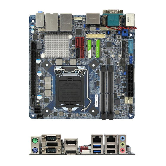
Page 9: Motherboard Layout
1.3 Motherboard Layout PANEL1 PLED PWRBTN ATXPWR1 HDLED RESET USB2_34 CPU_FAN1 USB3_34 MSATA_SEL1 CLRMOS1 CHA_FAN1 JGPIO_PWR1 LPC1 PWR_COM3 JGPIO_SET1 PWR_COM4 LPT1 PWR_JP1 JGPIO1 BUZZ1 PWR_COM1 DDR4_B1 PWR_COM2 DDR4_A1 mini PCIe mini PCIe / mSATA BLT_PWM1 SATA3_1 SATA3_3 SATA3_2 SATA3_4 BLT_PWR1 USB 3.0 Top: T: USB1... - Page 10 1 : ATX/AT Mode Select 2 : Digital Input/Output Power Select 3 : GPIO Default Setting 4 : mSATA Select 5 : COM Port PWR Setting Jumpers PWR_COM3 (For COM Port3) PWR_COM4 (For COM Port4) 6 : USB3.0 Header 7 : Printer Port Header 8 : USB2.0 Header 9 : LPC Header 10 : Digital Input/Output Pin Header...
-
Page 11: I/O Panel
1.4 I/O Panel PS/2 Mouse Port Microphone (Pink) COM Port (COM1)* USB 2.0 Ports (USB_12) DisplayPort (DP1) USB 3.0 Ports (USB3_12) LAN RJ-45 Port (LAN1)** DisplayPort (DP2) LAN RJ-45 Port (LAN2)** COM Port (COM2) Line In (Light Blue) PS/2 Keyboard Port Front Speaker (Lime) * This motherboard supports RS232/422/485 on COM1 port. -
Page 12: Installation
Chapter 2: Installation This is a Mini-ITX form factor (6.7" x 6.7", 17.0 x 17.0 cm) motherboard. Before you install the motherboard, study the configuration of your chassis to ensure that the motherboard fits into it. Make sure to unplug the power cord before installing or removing the motherboard. -
Page 13: Processor
2.3 Processor The board supports 6th generation Intel Core processors. Other processors may be supported in the future. This board supports processors with a maximum wattage of 65 W Thermal Design Power (TDP). NOTE This board has specific requirements for providing power to the processor. Additional ... -
Page 14: Installing The Cpu
2.3.1 Installing the CPU 1. Locate the CPU socket on the motherboard. Before installing the CPU, make sure that the socket box is facing towards you and the load lever is on your left. 2. Remove the PnP cap. 3. Press the load lever with your thumb (A), then move it to the left (B) until it is released from the retention tab. - Page 15 4. Position the CPU over the socket, making sure that the gold triangle is on the top-left corner of the socket then fit the socket alignment key into the CPU notch. Gold triangle CPU notch Alignment key 5. Pull back the load lever, then push the load lever (A) until it snaps into the retention tab.
-
Page 16: Installing The Cpu Heatsink And Fan
2.3.2 Installing the CPU Heatsink and Fan Intel® Core™ i7/ i5/ i3 LGA1151 processor requires a specially designed heatsink and fan assembly to ensure optimum thermal condition and performance. Install the motherboard to the chassis before you install the CPU fan and heatsink assembly. When you buy a boxed Intel® Core™ i7/ i5/ i3 LGA1151 processor, the package includes the CPU fan and heatsink assembly. If you buy a CPU separately, make sure that you use only Intel®... - Page 17 2. Push down two fasteners at a time in a diagonal A sequence to secure the heatsink and fan assembly in place. B A B A B A 3. Connect the CPU fan cable to the connector on the motherboard labeled CPU_FAN. Do ...
-
Page 18: Uninstalling The Cpu Heatsink And Fan
2.3.3 Uninstalling the CPU Heatsink and Fan To uninstall the CPU heatsink and fan: 1. Disconnect the CPU fan cable from the connector on the motherboard. 2. Rotate each fastener counterclockwise 3. Pull up two fasteners at a time in a diagonal sequence to disengage the heatsink and fan assembly from the motherboard. A B B A ... - Page 19 4. Carefully remove the heatsink and fan assembly from the motherboard. 5. Rotate each fastener clockwise to ensure correct orientation when reinstalling.
-
Page 20: Installation Of Memory Modules (So-Dimm)
2.4 Installation of Memory Modules (SO-DIMM) MX110H motherboard provides two DDR4 (Double Data Rate 4) SO-DIMM slots, which support Dual Channel DDR4. 1. It is not allowed to install a DDR, DDR2 or DDR3 memory module into a DDR4 slot; otherwise, this motherboard and SO-DIMM may be damaged. -
Page 22: Expansion Slot
2.5 Expansion Slots (mini-PCIe, mini-PCIe / mini-SATA and PCI Express Slots) There is 1 mini-PCIe slot, 1 mini-PCIe / mini-SATA slot and 1 PCI Express slot on this motherboard. mini-PCIe slot: MINI_PCIE1 (mini-PCIe slot; half size) is used for PCI Express mini cards. -
Page 23: Jumpers Setup
2.6 Jumpers Setup The illustration shows how jumpers are setup. When the jumper cap is placed on pins, the jumper is “Short”. If no jumper cap is placed on pins, the jumper is “Open”. The illustration shows a 3-pin jumper whose pin1 and pin2 are “Short”... - Page 24 COM Port Pin9 PWR Setting Jumpers 1-2: +12V 3-4: RI# (Default) (6-pin PWR_COM1, for COM Port1) 5-6: +5V (6-pin PWR_COM2, for COM Port2) (see p.9, No. 5) 1-2: +5V (Default) (3-pin PWR_COM3, for COM Port3) 2-3: +12V (3-pin PWR_COM4, for COM Port4) (see p.9, No.
-
Page 25: Onboard Headers And Connectors
2.7 Onboard Headers and Connectors Onboard headers and connectors are NOT jumpers. Do NOT place jumper caps over these headers and connectors. Placing jumper caps over the headers and connectors will cause permanent damage of the motherboard! SATA3 Connectors These four Serial ATA3 SATA3_1 SATA3_3 (SATA3) connectors support... - Page 26 HDLED (Hard Drive Activity LED): Connect to the hard drive activity LED on the chassis front panel. The LED is on when the hard drive is reading or writing data. The front panel design may differ by chassis. A front panel module mainly consists of power switch, reset switch, power LED, hard drive activity LED, speaker and etc.
- Page 27 CPU Fan Connector Please connect the CPU fan FAN_SPEED_CONTROL cable to the connector and (4-pin CPU_FAN1) CPU_FAN_SPEED +12V match the black wire to the (see p.9 No. 13) ground pin. Though this motherboard provides 4-Pin CPU fan (Quiet Fan) support, the 3-Pin CPU fan still can work successfully even without the fan speed control function.
- Page 28 Chassis Intrusion Headers This motherboard supports CASE OPEN detection feature (2-pin CI1, CI2: see p.9, No. 23) that detects if the chassis cover has been removed. This feature requires a chassis with chassis intrusion detection design. COM3, 4 Headers (RS232) PIN Signal Name PIN Signal Name (9-pin COM3/COM4: see p.9, No.
- Page 29 Digital Input/Output Pin Header (12-pin JGPIO1: see p.9, No. 10) Signal Signal Signal Signal PIN Signal Name PIN Signal Name Name Name Name Name 2 SIO_GP20 4 SIO_GP21 6 SIO_GP22 SIO_GP23 10 SMB_DATA 12 1 SIO_GP24 3 SIO_GP25 5 SIO_GP26 SIO_GP27 SMB_CLK 11 JGPIO_PWR...
-
Page 30: Bios Setup Utility
Chapter 3: BIOS SETUP UTILITY 3.1 Introduction This section explains how to use the BIOS SETUP UTILITY to configure your system. The Bios chip on the motherboard stores the BIOS SETUP UTILITY. You may run the BIOSSETUP UTILITY when you start up the computer. Please press <F2>... -
Page 31: Navigation Keys
3.1.2 Navigation Keys Please check the following table for the function description of each navigation key. Navigation Key(s) Function Description Moves cursor left or right to select Screens Moves cursor up or down to select items To change option for the selected items + / - To bring up the selected screen <Enter>... -
Page 32: Advanced Screen
3.3 Advanced Screen In this section, you may set the configurations for the following items: CPU Configuration, Chipset Configuration, Storage Configuration, Super IO Configuration, ACPI Configuration, and USB Configuration. Setting wrong values in this section may cause the system to malfunction. -
Page 33: Cpu Configuration
3.3.1 CPU Confi guration Active Processor Cores Use this item to select the number of cores to enable in each processor package. The default value is [All]. CPU C States Support Enable CPU C States Support for power saving. It is recommended to keep C3, C6 and C7 all enabled for better power saving. - Page 34 Intel Turbo Boost Technology Intel Turbo Boost Technology enables the processor to run above its base operating frequency when the operating system requests the highest performance state. CPU Thermal Throttling You may select [Enabled] to enable CPU internal thermal control mechanism to keep the CPU from overheating.
-
Page 35: Chipset Configuration
3.3.2 Chipset Confi guration Primary Graphics Adapter This allows you to select [Onboard] or [PCI Express] as the boot graphic adapter priority. The default value is [PCI Express]. Top of Lower Usable Dram The default value is [Dynamic]. VT-d ® ®... - Page 36 Front Panel Select [Auto] or [Disabled] for the onboard HD Audio Front Panel. Deep Sleep Mobile platforms support Deep S5 in DC only and desktop platforms sup- port Deep S5 in AC only. The default value is [Disabled]. Active LVDS Use this to enable or disable the LVDS.
-
Page 37: Storage Configuration
3.3.3 Storage Confi guration SATA Controller(s) Use this item to enable or disable the SATA Controller feature. SATA Mode Selection Use this to select SATA mode. Configuration options:[AHCI Mode] and [Disabled]. The default value is [AHCI Mode]. AHCI (Advanced Host Controller Interface) supports NCQ and other new features that will improve SATA disk perfor-mance. -
Page 38: Super Io Configuration
3.3.4 Super IO Confi guration COM1 Confi guration Use this to set parameters of COM1. Select COM1 port type: [RS232], [RS422] or [RS485]. COM2 Confi guration Use this to set parameters of COM2. COM3 Confi guration Use this to set parameters of COM3. COM4 Confi... -
Page 39: Acpi Configuration
3.3.5 ACPI Confi guration Suspend to RAM Use this item to select whether to auto-detect or disable the Suspend-to- RAM feature. Select [Auto] will enable this feature if the OS supports it. ACPI HPET Table Use this item to enable or disable ACPI HPET Table. The default value is [Enabled]. -
Page 40: Usb Configuration
3.3.6 USB Confi guration Legacy USB Support Use this option to select legacy support for USB devices. There are four configuration options: [Enabled], [Auto] and [UEFI Setup Only]. The default value is [Auto]. Please refer to below descriptions for the details of these four options: [Enabled] - Enables support for legacy USB. -
Page 41: Trusted Computing (Optional)
3.3.7 Trusted Computing (Optional) Security Device Support Enable or disable BIOS support for security device. -
Page 42: Hardware Health Event Monitoring Screen
3.4 Hardware Health Event Monitoring Screen In this section, it allows you to monitor the status of the hardware on your system, including the parameters of the CPU temperature, motherboard temperature, CPU fan speed, chassis fan speed, and the critical voltage. CPU_FAN1 Setting This allows you to set CPU_FAN1’s speed. -
Page 43: Security Screen
3.5 Security Screen In this section, you may set, change or clear the supervisor/user password for the system. Supervisor Password Set or change the password for the administrator account. Only the ad-ministrator has authority to change the settings in the BIOS Setup Utility. -
Page 44: Boot Screen
3.6 Boot Screen In this section, it will display the available devices on your system for you to confi gure the boot settings and the boot priority. Boot From Onboard LAN Use this item to enable or disable the Boot From Onboard LAN feature. Setup Prompt Timeout This shows the number of seconds to wait for setup activation key. - Page 45 CSM (Compatibility Support Module) Enable to launch the Compatibility Support Module. Please do not disable ® unless you’re running a WHCK test. If you are using Windows 8 64-bit and all of your devices support UEFI, you may also disable CSM for faster boot speed.
-
Page 46: Exit Screen
3.7 Exit Screen Reset System with ME disable Mode ME will run into the temporary disable mode. Ignore it if ME Ignition FW. Save Changes and Exit When you select this option, it will pop-out the following message, “Save configuration changes and exit setup?” Select [OK] to save the changes and exit the BIOS SETUP UTILITY. -
Page 47: Appendix
Appendix: GPIO Programming... - Page 49 GPIO Setting(GP20~GP27): 1.GP20: //Enter the Extended Function Mode IO_WRITE_BYTE(0x2E, 0x87); IO_WRITE_BYTE(0x2E, 0x87); // Configure the configuration registers //Switch to local device 7 IO_WRITE_BYTE(0x2E, 0x07); IO_WRITE_BYTE(0x2F, 0x07); //Activate GPIO group 2 IO_WRITE_BYTE(0x2E, 0x30); UCHAR Temp = IO_READ_BYTE(0x2F)|0x04; IO_WRITE_BYTE(0x2E, 0x30); IO_WRITE_BYTE(0x2F, Temp); //Programmed GPIO20 as an output port IO_WRITE_BYTE(0x2E, 0xE8);...
- Page 50 2.GP21: //Enter the Extended Function Mode IO_WRITE_BYTE(0x2E, 0x87); IO_WRITE_BYTE(0x2E, 0x87); // Configure the configuration registers //Switch to local device 7 IO_WRITE_BYTE(0x2E, 0x07); IO_WRITE_BYTE(0x2F, 0x07); //Activate GPIO group 2 IO_WRITE_BYTE(0x2E, 0x30); UCHAR Temp = IO_READ_BYTE(0x2F)|0x04; IO_WRITE_BYTE(0x2E, 0x30); IO_WRITE_BYTE(0x2F, Temp); //Programmed GPIO21 as an output port IO_WRITE_BYTE(0x2E, 0xE8);...
- Page 51 3.GP22: //Enter the Extended Function Mode IO_WRITE_BYTE(0x2E, 0x87); IO_WRITE_BYTE(0x2E, 0x87); // Configure the configuration registers //Switch to local device 7 IO_WRITE_BYTE(0x2E, 0x07); IO_WRITE_BYTE(0x2F, 0x07); //Activate GPIO group 2 IO_WRITE_BYTE(0x2E, 0x30); UCHAR Temp = IO_READ_BYTE(0x2F)|0x04; IO_WRITE_BYTE(0x2E, 0x30); IO_WRITE_BYTE(0x2F, Temp); //Programmed GPIO22 as an output port IO_WRITE_BYTE(0x2E, 0xE8);...
- Page 52 4.GP23: //Enter the Extended Function Mode IO_WRITE_BYTE(0x2E, 0x87); IO_WRITE_BYTE(0x2E, 0x87); // Configure the configuration registers //Switch to local device 7 IO_WRITE_BYTE(0x2E, 0x07); IO_WRITE_BYTE(0x2F, 0x07); //Activate GPIO group 2 IO_WRITE_BYTE(0x2E, 0x30); UCHAR Temp = IO_READ_BYTE(0x2F)|0x04; IO_WRITE_BYTE(0x2E, 0x30); IO_WRITE_BYTE(0x2F, Temp); //Programmed GPIO23 as an output port IO_WRITE_BYTE(0x2E, 0xE8);...
- Page 53 5.GP24: //Enter the Extended Function Mode IO_WRITE_BYTE(0x2E, 0x87); IO_WRITE_BYTE(0x2E, 0x87); // Configure the configuration registers //Switch to local device 7 IO_WRITE_BYTE(0x2E, 0x07); IO_WRITE_BYTE(0x2F, 0x07); //Activate GPIO group 2 IO_WRITE_BYTE(0x2E, 0x30); UCHAR Temp = IO_READ_BYTE(0x2F)|0x04; IO_WRITE_BYTE(0x2E, 0x30); IO_WRITE_BYTE(0x2F, Temp); //Programmed GPIO24 as an output port IO_WRITE_BYTE(0x2E, 0xE8);...
- Page 54 6.GP25: //Enter the Extended Function Mode IO_WRITE_BYTE(0x2E, 0x87); IO_WRITE_BYTE(0x2E, 0x87); // Configure the configuration registers //Switch to local device 7 IO_WRITE_BYTE(0x2E, 0x07); IO_WRITE_BYTE(0x2F, 0x07); //Activate GPIO group 2 IO_WRITE_BYTE(0x2E, 0x30); UCHAR Temp = IO_READ_BYTE(0x2F)|0x04; IO_WRITE_BYTE(0x2E, 0x30); IO_WRITE_BYTE(0x2F, Temp); //Programmed GPIO25 as an output port IO_WRITE_BYTE(0x2E, 0xE8);...
- Page 55 7.GP26: //Enter the Extended Function Mode IO_WRITE_BYTE(0x2E, 0x87); IO_WRITE_BYTE(0x2E, 0x87); // Configure the configuration registers //Switch to local device 7 IO_WRITE_BYTE(0x2E, 0x07); IO_WRITE_BYTE(0x2F, 0x07); //Activate GPIO group 2 IO_WRITE_BYTE(0x2E, 0x30); UCHAR Temp = IO_READ_BYTE(0x2F)|0x04; IO_WRITE_BYTE(0x2E, 0x30); IO_WRITE_BYTE(0x2F, Temp); //Programmed GPIO26 as an output port IO_WRITE_BYTE(0x2E, 0xE8);...
- Page 56 8.GP27: //Enter the Extended Function Mode IO_WRITE_BYTE(0x2E, 0x87); IO_WRITE_BYTE(0x2E, 0x87); // Configure the configuration registers //Switch to local device 7 IO_WRITE_BYTE(0x2E, 0x07); IO_WRITE_BYTE(0x2F, 0x07); //Activate GPIO group 2 IO_WRITE_BYTE(0x2E, 0x30); UCHAR Temp = IO_READ_BYTE(0x2F)|0x04; IO_WRITE_BYTE(0x2E, 0x30); IO_WRITE_BYTE(0x2F, Temp); //Programmed GPIO27 as an output port IO_WRITE_BYTE(0x2E, 0xE8);...
Need help?
Do you have a question about the MX110H and is the answer not in the manual?
Questions and answers