Table of Contents
Advertisement
Quick Links
Advertisement
Table of Contents

Related Manuals for BCM Advanced Research NX260N


Summary of Contents for BCM Advanced Research NX260N
- Page 1 NX260N Ver 1.0 User’s Manual 3rd Generation Intel® 32nm Atom™ N2600 Fanless Nano ITX Motherboard (Cedar Trail Platform) supports DC Power, provides greater battery life ideal for mobile/handheld device, retail and medical applications July 2012...
-
Page 2: Table Of Contents
NX260N Contents Before you Proceed ....................10 Motherboard Overview....................11 1.2.1 Placement Direction........................11 1.2.2 Screw Holes ..........................11 Motherboard Layout....................12 1.3.1 Layout Content List........................13 System Memory ......................14 1.4.1 DIMM Sockets Location ....................... 14 1.4.2 Memory Configurations........................ 14 1.4.3 Installing a DDR2 DIMM ......................15 1.4.4... -
Page 3: Safety Information
If you encounter technical problems with the product, contact a qualified service technician or your retailer. The symbol of the crossed out wheeled bin indicates that the product (electrical and electronic equipment) should not be placed in municipal waste. Check local regulations for disposal of electronic products. NX260N... -
Page 4: Safety Declaration
NX260N Safety Declaration This device complies with the requirements in Part 15 of the FCC rules. Operation is subject to the following two conditions: This device may not cause harmful interference. This device must accept any interference received, including interference that may cause undesired operation. -
Page 5: Packing List
User’s Manual Packing List Before you begin installing your single board, please make sure that the following materials have been shipped: 1 x NX260N Nano-ITX Motherboard 1 x CD-ROM contains the followings: User’s Manual in PDF file ... -
Page 6: Revision History
NX260N Revision History Revision Revision History Date V 0.1 First version for PCB 1.0 July, 2012 V 0.2 Add BIOS section Aug ,2012... -
Page 7: Specifications Summary
Audio Realtek ALC892, 5.1 + 2 CH HD Audio Audio Codec Line out (jack) , Mic. In & Line in (pin header) Audio Interface Ethernet Realtek RTL 8111E Gigabit LAN LAN1 * Specifications are subject to change without notice. NX260N... -
Page 8: Block Diagram
NX260N Block Diagram... - Page 9 User’s Manual This chapter describes the main board features and the new technologies it supports. Product Product introduction introduction NX260N...
-
Page 10: Before You Proceed
NX260N Production Introduction 1.1 Before you Proceed Take note of the following precautions before you install motherboard components or change any motherboard settings. Unplug the power cord from the wall socket before touching any component. Use a grounded wrist strap or touch a safely grounded object or a... -
Page 11: Motherboard Overview
Screw Holes Place four (4) screws into the holes indicated by circles to secure the motherboard to the chassis. Do not over tighten the screws! Doing so can damage the motherboard. Place this side towards the rear of the chassis. NX260N... -
Page 12: Motherboard Layout
NX260N 1.3 Motherboard Layout... -
Page 13: Layout Content List
SATA1 & 2 SATA Data Connector * 2 7P Male connector SATAPWR1 SATA Power Connector 2 x 2 female box header AAFP1 Mic-In & Line-In Connector 5 x 2 header, pitch 2.00mm USB23/45 USB Connector 5 x 2 header, pitch 2.00/2.54mm NX260N... -
Page 14: System Memory
NX260N 1.4 System Memory 1.4.1 DIMM Sockets Location The motherboard comes with two 200-pin Double Data Rate 3 (DDR3) SODIMM sockets. A DDR3 module has the same physical dimensions as a DDR2 DIMM but has a 204-pin footprint compared to the 200-pin DDR DIMM. DDR3 DIMMs are notched differently to prevent installation on a DDR2 DIMM socket. -
Page 15: Installing A Ddr2 Dimm
A DDR3 DIMM is keyed with a notch so that it fits in only one direction. DO NOT force a DIMM into a socket to avoid damaging the DIMM. The DDR3 DIMM sockets do not support DDR/DDR2 DIMMs. DO NOT install DDR/DDR2 DIMMs to the DDR3 DIMM socket. NX260N... -
Page 16: Removing A Ddr2 Dimm
NX260N 1.4.4 Removing a DDR3 DIMM 1. Press the two ejector tabs on the slot outward simultaneously, and then pull out the DIMM module. Support the DIMM lightly with your fingers when pressing the ejector tabs. The DIMM might get damaged when it flips out with extra force. -
Page 17: Expansion Slots
1. Turn on the system and change the necessary BIOS settings, if any. See Chapter 2 for information on BIOS setup. 2. Assign an IRQ to the card if needed. Refer to the tables on the next page. 3. Install the software drivers for the expansion card. NX260N... -
Page 18: Minipci Express Slot
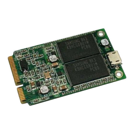
NX260N 1.5.4 MiniPCI express slot The miniPCI express slot supports Mini cards for WiFi , Bluetooth, SSD, COM, USB modules, and other cards that comply with the mini Card Rev. 1.2 specifications . The figure below shows the type of full size SSD card that can be installed on a miniPCI express slot. -
Page 19: Com1, Com2 Ri/+5V/+12V Select (Jcompwr1, Jcompwr2)
User’s Manual Normal (Default) Clear CMOS 1.6.2 COM1, COM2 RI/+5V/+12V Select (JCOMPWR1, JCOMPWR2) RI (Default) +12V NX260N... -
Page 20: Connectors
NX260N 1.7 Connectors 1.7.1 Rear Panel Connectors Label Function Description 12V DC-In Power Jack This power jack is connecting for 12V AC/DC pin 2.5mm power adapter . 12V 40W above is recommended . VGA1 VGA Connector This 15-pin port is for a VGA monitor or other VGA-compatible devices. -
Page 21: Lvds Connector (Jlvds)
Insufficient air flow inside the system may damage the motherboard components. This is not a jumper! DO NOT place a jumper cap on the fan connector. 1.7.3 LVDS Connector (JLVDS) This motherboard supports 18-bit single channel LVDS panel. NX260N... -
Page 22: Lcd Inverter Connector (Jbkl1)
NX260N 1.7.4 LCD Inverter Connector (JBKL1) This function will support the control of internal LVDS brightness. Signal Description Signal Signal Description For inverter with adjustable Backlight function, it is possible to control the LCD brightness through the VR signal. -
Page 23: System Panel Connector (F_Panel1)
The IDE LED lights up or flashes when data is read from or written to the HDD. Reset Button (2-pin RESET) This 2-pin connector is for the chassis-mounted reset button for a system reboot without turning off the system power. NX260N... -
Page 24: Serial Port Connector (Com1 & Com2 )
NX260N 1.7.6 Serial Port Connector (COM1 & COM2 ) These 2 connectors are for serial (COM) port. Connect the serial port module cable to this connector, and then install the module to a slot opening at the back of the system chassis. -
Page 25: Sata Data Connector (Sata1&2)
SATA Power Connector (SATAPWR1) This connector is for the provided SATA power cable. This power supply cable is designed to fit this connector in only one orientation. Find the proper orientation and push down firmly until the connector completely fits. NX260N... -
Page 26: Mic-In & Line-In Connector (Aafp1)
NX260N This 2x2P connector is for SATA power supply, plugging-in an ATX 2x2P power cable from PSU will damage this motherboard . 1.7.10 Mic-In & Line-In Connector (AAFP1) This connector is for the microphone-in and line-in function. 1.7.11 USB 2,3,4,5 Connector (USB 23/45) This connector is for USB 2.0 ports. - Page 27 User’s Manual Never connect a 1394 cable to the USB connectors. Doing so will damage the motherboard! The USB module is purchased separately. 1.7.12 Amplifier Connector (JAMP1) NX260N...
- Page 28 NX260N This chapter tells how to change the system settings through the BIOS setup menus. Detailed descriptions of the BIOS parameters are also provided. BIOS setup BIOS setup...
-
Page 29: Bios Setup
The BIOS setup screens shown in this section are for reference purposes only, and may not exactly match what you see on your screen. Visit the system builder’s website to download the latest BIOS file for this motherboard NX260N... - Page 30 NX260N 2.1.1 Legend Box The keys in the legend bar allow you to navigate through the various setup menus Key(s) Function Description ← Select Screen ↑↓ Select Item Change Option / Field Enter Go to Sub Screen PGDN Next Page...
- Page 31 To access the menu items, press the up/down/right/left arrow key on the keyboard until the desired item is highlighted, then press [Enter] to open the specific menu. NX260N...
- Page 32 NX260N...
- Page 33 User’s Manual 2.2.1 Main Use this menu for basic system configurations, such as time, date etc. 2.2.1.1 System Time The time format is <Hour> <Minute> <Second>. 2.2.1.2 System Date The date format is <Day>, <Month> <Date> <Year>. NX260N...
-
Page 34: Advanced Bios Setup
NX260N 2.1 Advanced BIOS Setup Select the Advanced tab from the setup screen to enter the Advanced BIOS Setup screen. You can select any of the items in the left frame of the screen, such as Chipset configuration, to go to the sub menu for that item. You can display an Advanced BIOS Setup option by highlighting it using the <Arrow>... - Page 35 Configuration options: [Disabled] [Enabled] Wake on LAN Control [Disable] Configuration options: [Disabled] [Enabled] Resume On RTC Alarm [Disable] Enable or disable system wake on alarm even. When enabled, system will wake upon the hr/min/sec specified. Configuration options: [Disabled] [Enabled] NX260N...
- Page 36 NX260N 2.4.3 CPU configuration CPU configuration Displays the CPU information Hyper-threading [Enabled] Enable or disable Hyper-threading support. Configuration options: [Disabled] [Enabled] Execute Disable Bit [Enable] XD can prevent certain classes of malicious buffer overflow attacks when combined with a supporting OS ( Windows Server 2003 SP1, Windows XP SP2, SuSE Linux 9.2 RedHat...
- Page 37 User’s Manual 2.4.5 IDE Configuration SATA Controller (S) [Enhanced] Enabled/Disabled SATA Controllers Configuration options: [Disable] [Enhanced] [Compatible] Configure SATA as [IDE Mode] Support IDE, AHCI or RAID mode Configuration options: [Disable][IDE Mode][AHCI Mode][RAID Mode] NX260N...
- Page 38 NX260N 2.4.6 USB Configuration USB Configuration Parameters USB Device Display how many devices are connected. Legacy USB Support [Enabled] Enables Legacy USB support. AUTO option disables legacy support if no USB devices are connected. DISABLE option will keep USB devices available only for EFI applications.
- Page 39 Maximum time the device will take before it properly reports itself to the Host Controller. ‘Auto’ uses default value: for a Root port it is 100ms, for a Hub port the delay is taken from Hub descriptor. 2.4.9 Super IO Configuration System Super IO Chip Parameters. Super IO Configuration Super IO Chip [W83627DHG] NX260N...
- Page 40 NX260N 2.4.10.1 Serial Port 1 configuration Set Parameters of Serial Port 1 (COMA) Serial Port 1 Configuration Serial Port [Enable] Enable or Disable Serial Port. Configuration options: [Disabled] [Enabled] Device Setting [IO=3F8h; IRQ=4] Change Setting[Auto] Select an optimal setting for Super IO device.
- Page 41 Configuration options: [Auto] [IO=2F8h; IRQ=3] [IO=3F8h; IRQ=3, 4, 5, 6, 7, 9. 10, 11, 12] [IO=2F8h; IRQ=3, 4, 5, 6, 7, 9. 10, 11, 12] [IO=3E8h; IRQ=3, 4, 5, 6, 7, 9. 10, 11, 12] [IO=2E8h; IRQ=3, 4, 5, 6, 7, 9. 10, 11, 12] NX260N...
- Page 42 NX260N 2.4.11 Hardware Monitor PC Health Stutus Display system health status Smart Fan Function [Enable] Enable or Disable Smart Fan Function Configuration options: [Disabled] [Enabled] 2.4.10.7 Smart Fan Mode Configruation Smart Fan Mode configuration...
- Page 43 User’s Manual System Smart Fan Target [Disable] Select system Fan mode Configuration options: [Disable] [Thermal Cruise Mode][SNART FAN IV Mode] NX260N...
- Page 44 NX260N 2.4.12 PPM Configuration EIST:[Enabled] Intel Speed Step technology option, the action needs perform under ACPI -based OS. CPU C-State Report [Enabled] Use this item to enable or disable CPUC-state report to OS. Enhanced C-state [Enabled] Use this item to enable or disable enhanced CPU C-state.
- Page 45 This option controls a programmable time for the CPU voltage to stabilize when exiting from a C4 state. C-state POPDOWN This item allows users to enable or disabled Intel C-state POPDOWN function. C-state POPUP This item allows users to enable or disabled Intel C-state POPUP function. 2.2 Chipset NX260N...
- Page 46 NX260N 2.5.1 Host Bridge Memory Information Display Memory Information...
- Page 47 MRC Fast Boot [Enabled] Bypasses longer memory training routines during system re-BOOT. Can help speed up BOOT times. Max TOLUD [Dynamic] Maximum Value of TOLUD. Dynamic assignment would adjust TOLUD automatically based on largest MMIO length of installed graphic controller NX260N...
- Page 48 NX260N 2.5.1.2 Display Configuration...
- Page 49 Enable or disable the control of Active State Power Management on SA side of the DMI Link. The choice: Disable, L0s, L1, L0sL1 High Precision Timer [Enable] Enable/Disable the High Precision Timer Configuration options: [Disabled] [Enabled] SLP_S4 Assertion Width [1~2 Seconds] Select a minimum assertion width of the SLP_S4 signal NX260N...
- Page 50 NX260N 2.5.2.1 TPT Device Azalia HD Audio [HD Audio] Enable/Disable Azalia HD Audio Configuration options: [Disabled] [HD Audio][Default] Audio Amplifier [21.2 db] Select USB Mode[By Controllers] Select USB mode to control USB ports. Configuration options:[By Ports][By Controllers][Default] ...
- Page 51 Control the USB UHCI (USB 1.1) functions. Disable from highest to lowest Controller Configuration options: [Disabled] [Enabled] USB 2.0(EHCI) Support [Enabled] Enable or Disable USB 2.0 (EHCI) Support SMBus Controller [Enable] Enable/Disable SMBus controller. Configuration options: [Disabled] [Enabled] 2.3 Boot Boot Configuration NX260N...
- Page 52 NX260N Setup Prompt Timeout [1] Number of seconds to wait for setup activation key. 65535(0xFFFF) means indefinite waiting. Bootup NumLock State [On] Select the keyboard NumLock state Configuration options: [On] [Off] Quick Boot [Disable] Configuration options: [Disable] [Enable] ...
- Page 53 User’s Manual 2.4 Security Administrator Password Set setup Administrator Password User Password Set User Password NX260N...
- Page 54 NX260N 2.5 Save & Exit Save changes and Exit Exit system setup after saving the changes. Discard changes and Exit Exit system setup without saving the changes. Save changes and Reset Reset the system after saving the changes.
- Page 55 Discard changes done so for to any of the setup option. Restore Defaults Restore/Load default values for all the setup option. Save as User Defaults Save the changes done so far as User Defaults. Restore User Defaults Restore the user defaults to all the setup options NX260N...
Need help?
Do you have a question about the NX260N and is the answer not in the manual?
Questions and answers