
Related Manuals for BCM Advanced Research BC77Q


Summary of Contents for BCM Advanced Research BC77Q
- Page 1 BC77Q Intel® Socket LGA1155 Generation Core i7/i5/i3 CPU ATX Motherboard User’s Manual Edition 1.00 – Oct, 2012...
- Page 2 Copyright Notice Copyright © 2011 BCM Advanced Research, ALL RIGHTS RESERVED. No part of this document may be reproduced, copied, translated, or transmitted in any form or by any means, electronic or mechanical, for any purpose, without the prior written permission of the original manufacturer.
- Page 3 Disclaimer BCM Advanced Research reserves the right to make changes, without notice, to any product, including circuits and/or software described or contained in this manual in order to improve design and/or performance. BCM Advanced Research assumes no responsibility or liability for the use of the described...
-
Page 4: Bcm Customer Services
In addition, free technical support is available from BCM engineers every business day. We are always ready to give advice on application requirements or specific information on the installation and operation of any of our products. Please do not hesitate to call or e-mail us. BCM Advanced Research 11 Chrysler, Irvine, California, 92618... -
Page 5: Product Warranty
Product Warranty BCM warrants to you, the original purchaser, that each of its products will be free from defects in materials and workmanship for two years from the date of purchase. This warranty does not apply to any products which have been repaired or altered by persons other than repair personnel authorized by BCM, or which have been subject to misuse, abuse, accident or improper installation. - Page 6 This manual describes in detail the BCM BC77Q Main board. We strongly recommend that you study this manual carefully before attempting to interface with BC77Q or change the standard configurations. Whilst all the necessary information is available in this manual we would recommend that unless you are confident, you contact your supplier for guidance.
-
Page 7: Table Of Contents
Contents Chapter 1: System Setup ....................Welcome! ............................12 Packing Contents..........................12 Special Features ...........................13 1.3.1 Product Highlights.........................13 Before you proceed........................14 Mainboard Overview ........................15 1.5.1 Placement Direction........................15 1.5.2 Mounting Holes ..........................16 1.5.3 Onboard LEDs ..........................17 1.5.4 Mainboard Layout .........................18 1.5.5 Layout Content List ........................19 1.5.5.1 Slots ..............................19 1.5.5.2... - Page 8 1.10.3 Chassis Intrusion Switch Connector: JCASE1 ................42 1.10.4 Front Panel Audio Connector: FPAUD1..................43 1.10.5 Amplifier Connector: JAMP1......................44 1.10.6 Front USB2.0 Headers: USB45, USB67, USB89, USB1011, USB1213 ........44 1.10.7 Serial Port Connectors: COM1, COM2, COM3, COM4..............45 1.10.8 LPT Port Connector: LPT1......................45 1.10.9 Front Panel Connectors: F_PANEL....................46 1.10.10...
- Page 9 3.6.3 Trust Computing ...........................62 3.6.4 CPU Configuration ........................63 3.6.5 SATA Configuration ........................64 3.6.6 PCH-FW Configuration .........................65 3.6.7 AMT Configuration ........................66 3.6.8 USB Configuration ........................67 3.6.9 Super IO Configuration ....................68 Second 3.6.9.1 Serial Port 1 Configuration......................69 3.6.9.2 Serial Port 2 Configuration......................70 3.6.9.3 Serial Port 3 Configuration......................71 3.6.9.4...
- Page 10 Mainboard Specifications Model BC77Q Processor Socket LGA1155 supports 3 Generation Core i7/i5/i3 CPU Chipset Intel® 4 x 240 Pin DIMM sockets supports DDR3 memory module (1.5V) 1066/ 1333/ 1600 Memory MHz up to 32GB (8GB maximum/slot) (1600MHz memory module only works with 3...
- Page 11 1 x PCI-E x 4 slot 2 x PCI-E x 1 slot 3 x PCI slot Onboard I/O Headers SATA 6 x Std. SATA Connectors 5 x USB Headers (10 ports on headers) RS232 4 x Headers 1 x Header Front Audio 1 x Header Amplifier...
-
Page 12: Chapter 1: System Setup
• Cable • 2 x Serial ATA Cable • 2 x COM port Cable • Accessories • 1 x BC77Q I/O Shield • Software CD • 1 x CD contains drivers, user’s manual, and QIG (Quick Installation Guide) • Documentation... -
Page 13: Special Features
1.3 Special Features 1.3.1 Product Highlights • Intel® i7/i5/i3 LGA1155 Processor Support This mainboard supports the 3 generation Intel® i7/i5/i3 processors in the LGA1155 package. • Intel® Q77 Express Chipset The Intel® Q77 PCH provides all business with more effective costs management, safer computing environment, and deploys more responsive PCs. -
Page 14: Before You Proceed
1.4 Before you proceed Take note of the following precautions before you install mainboard components or change any mainboard settings. • Unplug the power cord from the wall socket before touching any component inside the system. • Use a grounded wrist strap or touch a safely grounded object or to a metal object, such as the power supply case, before handling components to avoid damaging them due to static electricity. -
Page 15: Mainboard Overview
1.5 Mainboard Overview Before you install the mainboard, study the configuration of your chassis to ensure that the mainboard fits into it. Make sure to unplug the power cord before installing or removing the mainboard. Failure to do so can cause you physical injury and damage mainboard components. 1.5.1 Placement Direction When installing the mainboard, make sure that you place it into the chassis in the correct orientation. -
Page 16: Mounting Holes
1.5.2 Mounting Holes Place the screws into the mounting holes indicated by red squares to secure the mainboard to the chassis. Do not over-tighten the screws! Doing so may damage the mainboard. -
Page 17: Onboard Leds
1.5.3 Onboard LEDs The mainboard comes with a “Power On LED” (green) and one “Standby Power LED” (red) to indicate the system status. When the “Standby Power LED” lights on: It means the system is either in the standby state, or the power cable is still connected to the power source. -
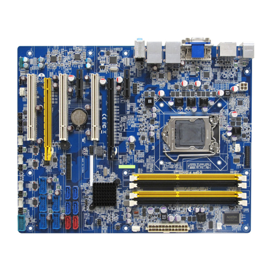
Page 18: Mainboard Layout
1.5.4 Mainboard Layout... -
Page 19: Layout Content List
1.5.5 Layout Content List • 1.5.5.1 Slots Label Function Note Page DIMMA1 240-pin DIMM slot 1 1. If there is only one memory module being installed in the system, install it on this slot first. 2. If there are only two memory modules being installed in the system, install these 2 modules on “DIMMA1”... -
Page 20: Internal Headers
• 1.5.5.3 Internal Headers Label Function Note Page ATX12V1 ATX Power Connector 2 x 2 header EATXPWR1 ATX Power Connector 12 x 2 header SATA1 Serial ATA Connectors 1~6 7-pin header SATA2 SATA3 SATA4 SATA5 SATA6 CPU_FAN1 CPU Fan Connector 4 x 1 wafer, pitch 2.54mm CHA_FAN1 Chassis Fan Connector... -
Page 21: Back Panel Connectors
• 1.5.5.4 Back Panel Connectors Label Function Note Page KBMS PS/2 keyboard and mouse 6-pin Mini-Din 37, 38 VGA/ DVI VGA Connector x 1 D-sub 15-pins, female 37, 38 DVI Connector x 1 Dual Link DVI-D; 24-pins DP1/ DP2 Display Port x 2 (COM1/ COM2) 37, 38 LAN1/ LAN2 RJ-45 Ethernet Connector x 2... -
Page 22: Central Processing Unit (Cpu)
1.6 Central Processing Unit (CPU) This mainboard supports the Intel® LGA1155 socket for 3 generation Intel® Core™ i7/i5/i3 32nm desktop processors. If you do not have the CPU cooler, consult with your dealer before turning on the system. • Your boxed Intel® LGA1155 processor package should come with installation instructions for the CPU, fan, heatsink, and the retention assembly. -
Page 23: Installing The Cpu
1.6.1 Installing the CPU To install a CPU 1. Locate the CPU socket (LGA1155 Socket) on the mainboard. 2. Unlatch the “CPU Socket Lever” by pressing the lever down and move it away from the main structure of the socket. To prevent damage to the socket pins, do not remove the “CPU Socket Cover”... - Page 24 3. Lift the load lever up in the direction of the arrow to a 135° angle, so the metal “CPU Socket Cover” can also be lifted. 4. The CPU socket has a plastic protection cap installed on it (black color, a.k.a. “CPU Socket Cover”, or “PnP cap”) in order to protect the socket pins from damage.
- Page 25 5. There are two notches on the CPU itself (one on each side), and there are two “Socket Alignment keys” on the CPU socket as well. Line up the two CPU notches with the “Socket Alignment Keys” on the socket, and insert the CPU into the CPU socket slowly. 6.
- Page 26 7. Close the “CPU Socket Cover” by lowering down the “CPU Socket Lever”. Make sure the “CPU Socket Front Plates” are sliding underneath the “Shoulder Screw Cap”. 8. Secure the “CPU Socket Cover” by keep pressing down the “CPU Socket Lever” and move it toward and underneath the “Load Plate Tab”.
-
Page 27: Installing The Cpu Heatsink And Fan
1.6.2 Installing the CPU Heatsink and Fan The Intel LGA1155 processor requires a specially designed heatsink and fan assembly to ensure optimum thermal condition and performance. • When you purchase a boxed Intel® processor, the package includes the CPU fan and heatsink assembly. - Page 28 Push down two fasteners at a time in a diagonal sequence to secure the heatsink and fan assembly in place 3. Connect the CPU fan cable to the connector on the motherboard labeled “CPU_FAN1”. 1. Do not forget to connect the CPU fan connector. Insufficient air flow inside the system chassis may damage the mainboard components.
-
Page 29: Uninstalling The Cpu Heatsink And Fan
1.6.3 Uninstalling the CPU Heatsink and Fan. To uninstall the CPU heatsink and fan: 1. Disconnect the CPU fan cable from the connector on the mainboard. 2. Rotate each fastener counterclockwise. 4. Pull up two fasteners at a time in a diagonal sequence to disengage the heatsink and fan assembly from the mainboard. - Page 30 5. Rotate each fastener clockwise to ensure correct orientation when reinstalling. The narrow end of the groove should point outward after resetting. (The photo shows the groove shaded for emphasis.)
-
Page 31: System Memroy
1.7 System Memory 1.7.1 Overview The mainboard comes with four 240-pin Double Data Rate 3 (DDR3) Dual Inline Memory Modules (DIMM) slots. You may ONLY use 1600MHz (PC3-12800, only works with 3 generation Core i7/ i5/ i3 processors), or 1066MHz (PC3-8500), or 1333MHz (PC3-10600); Non-ECC, Un-buffered 1.5V DDR3 memory modules on this board (8GB maximum for each slot). -
Page 32: Configurations Of Supported Memory Modules (Non-Ecc, Unbuffered)
1.7.2 Configurations of Supported Memory Modules (Non-ECC, Unbuffered) Memory Module Configuration SDRAM SDRAM Number of SDRAM Capacity (Chips populated on Density Organization Devices single side or both sides Front-side/ (total of memory of memory module) Back-side chips on each memory module) Single sided 1 Gbit 128M x8 /empty... -
Page 33: Dual-Channel Mode Population Rule
1.7.3 Dual-Channel Mode Population Rule In Dual-Channel mode, the memory modules can transmit and receive data with two data bus lines simultaneously. Enabling Dual-Channel mode can enhance the system performance. Please refer to the following illustrations for population rules under Dual-Channel mode. •... -
Page 34: Installing Dimm
1.7.4 Installing DIMM Make sure to unplug the power supply before adding or removing DIMMS or other peripherals from the system. Failure to do so may cause severe damage to both the mainboard and the peripherals. 1. Unlock a DIMM socket by pressing the retaining clips outward. 2. - Page 35 1. A DDR3 memory module is keyed with a notch so that it fits in only one direction. 2. DO NOT force the memory module into the socket in order to avoid damaging the memory module and the slot. 3. DDR3 memory modules are not interchangeable with DDR or DDR2. 4.
-
Page 36: Removing A Dimm
1.7.5 Removing DIMM Follow these steps to remove a DIMM. 1. Simultaneously press the retaining clips outward to unlock the DIMM. 2. Remove the DIMM from the socket. -
Page 37: Power Supply
1.8 Power Supply 1.8.1 ATX Power Connectors: EATXPWR1, ATX12V1 These ATX power connectors provide connections from power supply unit (PSU) to the mainboard. Both connectors need to be installed in order for the mainboard to function properly. The power supply plugs are designed to fit with these ATX power connectors in one orientation only. To connect these power supply plugs;... -
Page 38: Back Panel
Back Panel 1.9.1 Back Panel Connectors Item Name Function Description KBMS PS/2 Mouse The port is for a PS/2 mouse. Connector Display Port 2 Provides “displayport” type connection to monitor. VGA Video Port The VGA15-pin Connector. LAN1/ Gigabit LAN This port allows Gigabit connection to a Local Area LAN2 (RJ-45) Connectors Network (LAN) through a network hub. - Page 39 AUDIO Microphone port This port connects a microphone. (Pink) USB 3.0 Connectors These two 4-pin Universal Serial Bus (USB) ports are available for connecting USB 3.0/ 2.0 devices. USB 3.0 Connectors These two 4-pin Universal Serial Bus (USB) ports are available for connecting USB 3.0/ 2.0 devices. DVI Video Port DVI-D 24-Pin Connector.
-
Page 40: Connectors/Headers
1.10 Connectors/ Headers 1.10.1 Serial ATA Connectors: SATA3.0: SATA1, SATA2 SATA2.0: SATA3, SATA4, SATA5, SATA6 SATA ports “SATA1” and “SATA2” (in red color connectors) support SATA3.0 standard, which is backward compatible with SATA2.0. SATA ports “SATA3” to “SATA6” (in blue color connectors) support SATA2.0 standard. Please do not fold the Serial ATA cable into 90-degree angle. -
Page 41: Fan Power Connectors: Cpu_Fan1, Cha_Fan1, Sys_Fan1
1.10.2 Fan Power Connectors: CPU_FAN1, CHA_FAN1, SYS_FAN1 The fan power connectors support system cooling fan with +12V. When connecting the wire to these fan connectors, please note that the red wire is designated as “Power” and should be connected to “+12V” pin; the black wire is designated as “Ground”... -
Page 42: Chassis Intrusion Switch Connector: Jcase1
1.10.3 Chassis Intrusion Switch Connector: JCASE1 This connector connects to a 2-pin chassis switch. If the chassis is opened, the switch will be short. The system will record this status and show a warning message on the screen. To clear the warning message, you must enter the BIOS and clear the record. -
Page 43: Front Panel Audio Connector: Fpaud1
1.10.4 Front Panel Audio Connector: FPAUD1 This connector allows you to connect the front panel audio and is compliant with Intel® Front Panel I/O Connectivity Design Guide. -
Page 44: Amplifier Connector: Jamp1
1.10.5 Amplifier Connector: JAMP1 This header provided amplified audio signals to external speakers (2-channels). The dB level can be adjusted under BIOS. 1.10.6 Front USB2.0 Headers: USB45, USB67, USB89, USB1011, USB1213 This connector is compliant with Intel® I/O Connectivity Design Guide, which is ideal for connecting high-speed USB peripherals such as USB HDD, USB digital cameras, USB MP3 players, USB printers, etc. -
Page 45: Serial Port Connectors: Com1, Com2, Com3, Com4
1.10.7 Serial Port Connectors: COM1, COM2, COM3, COM4 This connector is a 16550A high speed communication port that sends/receives 16 byte FIFOs. 1.10.8 LPT Port Connector: LPT1... -
Page 46: Front Panel Connectors: F_Panel
1.10.9 Front Panel Connectors: F_PANEL These connectors are for electrical connections to the front panel switches and LEDs. The “F_PANEL1” connector is compliant with Intel® Front Panel I/O Connectivity Design Guide. 1.10.10 LANLED Header: LANLED1 The “LANLED1” header provides the option for front panel to display the LED status simultaneously with the corresponding RJ45 port. -
Page 47: Digital I/O Connector: Dio
1.10.11 Digital I/O Connector: DIO This header provides connections to GPIO ports. 1.10.12 RAID LED Header: SGPIO1 This header is reserved. 1.10.13 The Header: SPI_CN This header is reserved for factory use only. -
Page 48: Jumpers
1.11 Jumpers 1.11.1 Clear CMOS Jumper: CLRTC1 There is a CMOS RAM onboard that has a power supply from an external battery to keep the data of system configuration. For normal state (default), the jumper is set on pin location 1 and 2. To clear the CMOS, set the jumper to pin location 2 and 3 for at least 30 seconds while the system is off. -
Page 49: Com Port Ring-In/ +12V/ +5V Power Select: Jcompwr1, Jcompwr2, Jcompwr3, Jcompwr4
1.11.3 COM Port Ring-in/ +12V/ +5V Power Select: JCOMPWR1, JCOMPWR2, JCOMPWR3, JCOMPWR4 These headers provide ring-in, or 5V, or 12V on the com ports. 1.11.4 ATX/AT Mode Selection: PSON1 This header provides the option to boot the system in the form of ATX mode (default) or AT mode. When the system is set in AT mode, the system power on/off will be controlled directly by the power switch on power supply. -
Page 50: The Expansion Slots
1.12 The Expansion Slots In the future, you may need to install expansion cards. The following sub-sections describe the expansion slots and the expansion cards that they support. Make sure to unplug the power cord before adding or removing expansion cards. Failure to do so may cause you physical injury and damage mainrboard components. -
Page 51: Pci-Ex16 Slot: Pciex16
1.12.3.1 PCI-E x 16 Slot: PCIEX16 The PCIEX16 slot supports PCI-E x16 graphic card. • When PCIEX16 slot installed with PCI-E x16 graphic card, there will be no video output from onboard Displayport, VGA, DVI ports. 1.12.3.2 PCI-E x 4 Slot: PCIEX4_1 The PCIEX4_1 slot supports PCI-E transfer rate up to 4x ONLY. -
Page 52: Chapter 2: Starting Up The System
Chapter 2: Starting Up the System Starting Up Your System After all connections are made, close your computer case cover. Be sure all the switches are off, and check that the power supply input voltage is set to the local voltage, usually in-put voltage is 220V∼240V or 110V∼120V depending on your country’s voltage used. - Page 53 Power off your computer: You must first exit or shut down your operating system before switch off the power switch. For ATX power supply, you can press ATX power switching after exiting or shutting down your operating system. If you use Windows Operating Systems, click “Start” button, click “Shut down”...
-
Page 54: Chapter 3: Bios Setup
Chapter 3: BIOS Setup Warnining: Before flashing the BIOS, please be sure to make the following adjustments on the system: 1. Fully disabled the iAMT feature (through Intel ME management utility during system post). 2. Flash the mainboard with memory module installed on memory slot “DIMMB2” ONLY. No memory module occupied on memory slots “DIMMA1”, “DIMMA2”... -
Page 55: Entering Bios Setup Menu
• Press Page Up/Page Down or +/– keys when you want to modify the BIOS parameters for the active option. Entering BIOS Setup Menu Power on the computer and by pressing <DEL> immediately allows you to enter BIOS Setup Menu. If you are not able to enter the BIOS menu but you still wish to enter Setup, restart the system to try again by turning it OFF then ON or pressing the “RESET”... -
Page 56: Bios Menu Screen
BIOS Menu Screen When entering the BIOS, the following screen appears. The BIOS menu screen displays the items that allow user to make changes to the system configuration. To access the menu items, press the up/down/right/left arrow key on the keyboard until the desired item is highlighted, then press [Enter] to access the specific menu. -
Page 57: Main Menu
Main Menu This menu gives user an overview of the general system specifications. The BIOS automatically detects the items in this menu. This menu provides basic system information, such as installed memory size, time, date etc. • BIOS Information Displays the auto-detected BIOS information. •... -
Page 58: Advanced Menu
Advanced Menu Select the “Advanced” tab from the BIOS menu screen to enter the Advanced BIOS Setup screen. NOTE: Take caution when changing the settings of the Advanced menu items. Incorrect field values can cause the system not to function properly. -
Page 59: Pci Subsystem Setting
3.6.1 PCI Subsystem Setting The PCI PnP menu items allow you to change the advanced settings for PCI/PnP devices. This menu includes setting IRQ and DMA channel resources for either PCI/PnP or legacy ISA devices, and setting the memory size block for legacy ISA devices. •... -
Page 60: Acpi Settings
3.6.2 ACPI Settings • ACPI Sleep State [S3 (suspend to RAM)] Select the highest ACPI sleep state the system will enter the SUSPEND button is press. Configuration options: [Suspend Disabled], [S1 (CPU Stop Clock)], [S3 (suspend to RAM )] • S3 Video Repost Allows you to determine whether to invoke VGA BIOS POST on S3/STR resume. - Page 61 • Wake on PCI PME Configuration options: [Disabled] [Enabled]...
-
Page 62: Trusted Computing
3.6.3 Trusted Computing Trusted computing (TPM) settings. • Security Device Support [Disabled] Enable or disable TPM support. Configuration options: [Disabled], [Enabled] • Current Status Information Displays the TPM status information [SUPPORT TURNED OFF]... -
Page 63: Cpu Configuration
3.6.4 CPU Configuration • CPU configuration Displays the CPU information • Active Processor Cores [All] Select the numbers of cores in each processor package. Configuration options: [All], [1], [2], [3], [4], [5], [6], [7] NOTE: The availability of options depends on the type of CPU installed. •... -
Page 64: Sata Configuration
3.6.5 SATA Configuration • SATA Controller(s) [Enabled] Enabled/Disabled Serial ATA Controller. Configuration options: [Disabled], [Enabled] • SATA Mode [IDE] Support IDE, AHCI or RAID mode Configuration options: [IDE], [AHCI], [RAID]... -
Page 65: Pch-Fw Configuration
3.6.6 PCH-FW Configuration Intel ME Configuration... -
Page 66: Amt Configuration
3.6.7 AMT Configuration AMT Configuration Parameters • Intel AMT [Disabled] Enable/Disable access to Intel AMT extension ROM menu during system post. Configuration options: [Disabled], [Enabled] • Un-configure ME [Disabled] Use this item to enable/ disable un-configure ME without password. Configuration options: [Disabled], [Enabled]... -
Page 67: Usb Configuration
3.6.8 USB Configuration USB Configuration Parameters • USB Device Display how many devices are connected. • Legacy USB Support [Enabled] Enables Legacy USB support. “AUTO” option disabled legacy support if no USB device is connected. “Disabled” option will keep USB devices available only for EFI applications. Configuration options: [Enabled], [Disabled], [Auto]... -
Page 68: Second Super Io Configuration
3.6.9 Second Super IO Configuration System Super IO Chip Parameters Super IO Configuration Super IO Chip [Finteck F81216]... -
Page 69: Serial Port 1 Configuration
3.6.9.1 Serial Port 1 Configuration Set Parameters of Serial Port 1 Serial Port 1 Configuration • Serial Port [Enable] Enable or Disable Serial Port. Configuration options: [Disabled], [Enabled] • Device Setting [IO=3F8h; IRQ=4] • Change Setting[Auto] Select an optimal setting for Super IO device. Configuration options: [Auto], [IO=3F8h;... -
Page 70: Serial Port 2 Configuration
3.6.9.2 Serial Port 2 Configuration Set Parameters of Serial Port 2 Serial Port 2 Configuration • Serial Port [Enabled] Enable or Disable Serial Port. Configuration options: [Disabled], [Enabled] • Device Setting [IO=2F8h; IRQ=3] • Change Setting[Auto] Select an optimal setting for Super IO device. Configuration options: [Auto], [IO=2F8h;... -
Page 71: Serial Port 3 Configuration
3.6.9.3 Serial Port 3 Configuration Set Parameters of Serial Port 3 Serial Port 3 Configuration • Serial Port [Enabled] Enable or Disable Serial Port. Configuration options: [Disabled], [Enabled] • Device Setting [IO=C80h; IRQ=5] • Change Setting[Auto] Select an optimal setting for Super IO device. Configuration options: [Auto], [Auto] [IO=C80h;... -
Page 72: Serial Port 4 Configuraiton
3.6.9.4 Serial Port 4 Configuration Set Parameters of Serial Port 4 Serial Port 4 Configuration • Serial Port [Enabled] Enable or Disable Serial Port. Configuration options: [Disabled], [Enabled] • Device Setting [IO=C88h; IRQ=5] • Change Setting[Auto] Select an optimal setting for Super IO device. Configuration options: [Auto], [IO=C88h;... -
Page 73: Parallel Port Configuration
3.6.10 Parallel Port Configuration Set Parameters of parallel Port • Parallel Port [Enable] Use this item to enable or disable the onboard parallel port. Configuration options: [Disabled], [Enabled] • Change Settings [Auto] Use this item to select an optional setting for Super IO device. Configuration Options : [Auto], [IO=378h;... - Page 74 • Watch Dog Timer Use this item to enable/disable Watch Dog Timer Configuration options: [Disabled], [Enabled] • Chassis Opened Warning Configuration options: [Disabled], [Enabled]...
-
Page 75: Hardware Monitor
3.6.11 Hardware Monitor Display system health status... -
Page 76: Smart Fan
3.6.11.1 Smart Fan • Smart Fan Function [Enabled] Configuration options: [Disabled], [Enabled]... -
Page 77: Smart Fan Mode Configuration
3.6.11.2 Smart Fan Mode Configuration Smart Fan Mode configuration • Chassis Smart Fan Target [Disabled] Select Chassis Smart Fan mode Configuration options: [Disabled], [Enabled] Once enabled, user may choose the desired % of minimum throttle output for the fan connected to Chassis Fan header. - Page 78 • System Smart Fan Target [Disabled] Select System Smart Fan mode Configuration options: [Disabled], [Enabled] Once enabled, user may choose the desired % of minimum throttle output for the fan connected to System Fan header. Configuration options : [12.5%], [25%], [37.5%], [50%], [62.5%], [75%], [87.5%]...
-
Page 79: Option Rom Policy
3.6.12 Option ROM Policy Setup Option ROM related policy • Launch Storage OpROM Policy [Enabled] Enable or Disable Boot Option For Legacy Mass Storage Devices with Option ROM Configuration options: [Disabled], [Enabled] • Other PCI Device ROM priority [UEFI OpROM] Configuration options: [UEFI OpROM], [Legacy OpROM]... -
Page 80: Cpu Ppm Configuration
3.6.13 CPU PPM Configuration Setup CPU related parameters • EIST [Enabled] Enable or disable speed step. Configuration options: [Disabled], [Enabled] • CPU C3 State Support [Enabled] Use this to enable or disable CPU C3 (ACPI C2) report to OS. Configuration options: [Disabled], [Enabled] •... - Page 81 • CPU C7 State Support [Enabled] Use this to enable or disable CPU C7 report to OS. Configuration options: [Disabled], [Enabled]...
-
Page 82: Chipset
Chipset Setup chipset related parameters... -
Page 83: Pch-Io Configuration
3.7.1 PCH-IO Configuration Setup PCH-IO Configuration • LAN1 Controller [Enable] Enable/Disable LAN1 Controller Configuration options: [Disabled], [Enabled] • LAN1 Option-ROM [Disable] Enable/Disable LAN1 boot option for legacy network devices. Configuration options: [Disabled], [Enabled] • Wake on LAN1 from S5 [Disable] Configuration options: [Disabled], [Enabled]... - Page 84 • LAN2 Controller [Enable] Enable/Disable LAN1 Controller Configuration options: [Disabled], [Enabled] • LAN2 Option-ROM [Disable] Enable/Disable LAN2 boot option for legacy network devices. Configuration options: [Disabled], [Enabled] • Wake on LAN2 from S5 [Disable] Configuration options: [Disabled], [Enabled] • Restore AC Power Loss [Power Off] Specify what state to go to when power is re-applied after a power failure(G3 state).
-
Page 85: Usb Configuration
3.7.2 USB Configuration Setup USB related parameters • EHCI controller 1 [Enabled] Enable/Disable USB 2.0(EHCI) support Configuration options: [Disabled], [Enabled] • EHCI controller 2 [Enabled] Enable/Disable USB 2.0(EHCI) support Configuration options: [Disabled], [Enabled] • USB ports per-port disable cont [Disabled] Configuration options: [Disabled], [Enabled]... -
Page 86: System Agent (Sa) Configuration
System Agent (SA) Configuration System related parameters • VT-d [Enabled] Set VT-d Enable or Disable Configuration options: [Enabled], [Disabled]... -
Page 87: Graphics Configuration
3.8.1 Graphics Configuration Setup Graphic related parameters • Primary Display [Auto] Select which graphics controller to use as the primary boot device. Configuration options: [Auto], [IGD], [PEG], [PCI] • IGD Multi-Monitor [Disabled] Enable/Disable IGD Multi-Monitor by internal graphics device. Configuration options: [Disabled], [Enabled] •... - Page 88 • DVMT Total Graphic Memory [128MB] Select DVMT/FIXED Mode Memory size used by Internal Graphic Device. Configuration options: [128MB], [256MB], [Maximum] • Primary Display [VBIOS Default] If there are more than one display devices attached to the system, this option can select which display device will be activated during system post as primary display.
-
Page 89: Pcie Configuration
3.8.2 PCIe Configuration PCI-E bus related parameters • PEG0 – Gen X [Auto] Configure PEG0 B0 :D1 :F0 Gen1-Gen3. Configuration options: [Auto], [Gen1], [Gen2], [Gen3] • PEG0 ASPM [Auto] Power management related feature ASPM, support for the PEG : Device 1 Function 0. This has no effect if PEG is not the currently active device. -
Page 90: Boot
Boot Setup boot related parameters • Setup Prompt Timeout [3] Number of seconds to wait during system post. • Bootup NumLock State [On] Select the keyboard NumLock state Configuration options: [On], [Off] • Customer Logo [Disable] Display the custom added customer logo. Configuration options: [Disable], [Enable]... -
Page 91: Uefi Boot Drive Bbs Priorities
3.9.1 UEFI Boot Drive BBS Priorities Setup boot related parameter under UEFI category • UEFI Boot Drive BBS Priorities Select the system boot order. Configuration options: [Built-in EFI Shell], [Disabled]... -
Page 92: Security
3.10 Security Setup the password • Administrator Password Set setup Administrator Password • User Password Set User Password... -
Page 93: Save & Exit
3.11 Save & Exit Options for loading the optimized BIOS default ; and whether to save or discard the BIOS settings before leaving the BIOS menu. • Save changes and Exit Exit system setup after saving the changes. • Discard changes and Exit Exit system setup without saving the changes.
Need help?
Do you have a question about the BC77Q and is the answer not in the manual?
Questions and answers