
Subscribe to Our Youtube Channel
Related Manuals for BCM Advanced Research ECM-APL


Summary of Contents for BCM Advanced Research ECM-APL
- Page 1 ECM-APL Intel® Pentium® /Celeron® /Atom™ SoC Processor 3.5”Micro Module User’s Manual Ed – 22 March 2017 Part No. E2047393001R...
- Page 2 We assume no responsibility or liability for the use of the described product(s), conveys no license or title under any patent, copyright, or masks work rights to these products, and makes no representations or warranties that 2 ECM-APL User’s Manual...
- Page 3 For the most frequently asked questions, you can easily find answers in your product documentation. These answers are normally a lot more detailed than the ones we can give over the phone. So please consult the user’s manual first. ECM-APL User’s Manual...
- Page 4 A product returned without proof of the purchase date is not eligible for warranty service. Write the RMA number visibly on the outside of the package and ship it prepaid to your dealer. 4 ECM-APL User’s Manual...
-
Page 5: Table Of Contents
PC Buzzer header (JBZ1) ......................28 2.3.20 Battery connector (BT1) ......................29 2.3.21 Audio connector (JAUDIO1) ...................... 29 Signal Description – Audio connector (JAUDIO1) ..............29 2.3.21.1 3.BIOS Setup ........................30 Introduction ......................31 Starting Setup ......................31 ECM-APL User’s Manual... - Page 6 South Cluster Configuration ....................51 3.6.3.4.1 HD-Audio Configuration ......................52 3.6.3.4.2 PCI Express Configuration ....................52 3.6.3.4.2.1 PCI Express Root Port 3(i210/211) ..................53 3.6.3.4.2.2 PCI Express Root Port 4(i210/211) ..................54 3.6.3.4.2.3 PCI Express Root Port 5(mPCIe) ..................55 6 ECM-APL User’s Manual...
- Page 7 Install TXE Driver ....................65 Install VGA Driver ....................66 Install Audio Driver (For Realtek ALC892) .............. 68 Install Ethernet Driver ....................69 Install Serial IO Driver ..................... 71 Install Touch Driver ....................73 5. Mechanical Drawing ....................75 ECM-APL User’s Manual...
-
Page 8: Getting Started
1.2 Packing List Before you begin installing your single board, please make sure that the following materials have been shipped: 1 x 3.5” ECM-APL Micro Module 1 x DVD-ROM contains the followings: ... -
Page 9: Document Amendment History
User’s Manual 1.3 Document Amendment History Revision Date Comment December 2016 Initial Release March 2017 Add JLVDS1 and JBKL1 matching connector ECM-APL User’s Manual... -
Page 10: Manual Objectives
We strongly recommend that you study this manual carefully before attempting to set up ECM-APL or change the standard configurations. Whilst all the necessary information is available in this manual we would recommend that unless you are confident, you contact your supplier for guidance. -
Page 11: System Specifications
LVDS: 1920 x 1080@60Hz Resolution Dual HDMI: 3840 x 2160@30Hz Multiple Display Dual HDMI+LVDS HDMI HDMI x 1.4b Dual channel 18/24-bit LVDS (via 7511B) Interface Audio AC97 Codec Realtek ALC892 Audio Amp Mic-In, Line-In and Line-Out Ethernet ECM-APL User’s Manual 11... - Page 12 0% ~ 90% relative humidity, non-condensing Humidity Size (L x W) 5.7" x 4" (146mm x 101mm) Weight 0.44lbs (0.2kg) OS information: Win10 (64) /Linux/Android OS support (listed in accordance with Intel document) Note: Specifications are subject to change without notice. 12 ECM-APL User’s Manual...
-
Page 13: Architecture Overview-Block Diagram
User’s Manual 1.6 Architecture Overview—Block Diagram The following block diagram shows the architecture and main components of ECM-APL. ECM-APL User’s Manual 13... -
Page 14: Hardware Configuration
ECM-APL User’s Manual 2. Hardware Configuration 14 ECM-APL User’s Manual... -
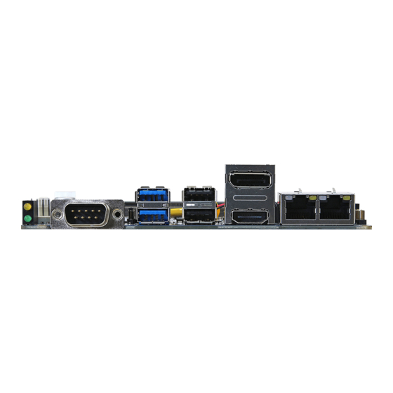
Page 15: Product Overview
User’s Manual 2.1 Product Overview ECM-APL User’s Manual 15... - Page 16 ECM-APL User’s Manual 16 ECM-APL User’s Manual...
-
Page 17: Jumper And Connector List
CPU_FAN1 CPU fan connector 4 x 1 wafer, pitch 2.54 mm JAUDIO1 Audio connector 6 x 2 header, pitch 2.00 mm 5 x 1 wafer, pitch 2.00 mm JBKL1 LCD inverter connector Matching Connector: JST PHR-5 ECM-APL User’s Manual 17... - Page 18 2 x 1 wafer, pitch 2.00 mm SATA1 Serial ATA connector 1 HDMI1 HDMI connector BIOS SPI header 4 x 2 header, pitch 2.00 mm BIOS_SPI1 M.2 B key slot NGFF1 Mini-PCI connector MINI_PCIE1 SO_DIMM1 DDR3 SODIMM connector USIM1 Sim card slot 18 ECM-APL User’s Manual...
-
Page 19: Setting Jumpers & Connectors
User’s Manual 2.3 Setting Jumpers & Connectors 2.3.1 AT/ ATX Input power select (JAT1) * Default 2.3.2 Serial port 1 pin9 signal select (JRI1) Ring* +12V * Default ECM-APL User’s Manual 19... -
Page 20: Clear Cmos (Jbat1)
ECM-APL User’s Manual 2.3.3 Clear CMOS (JBAT1) Protect* Clear CMOS * Default 2.3.4 LCD backlight brightness adjustment (JBKL_SEL1) PWM Mode* DC Mode * Default 20 ECM-APL User’s Manual... -
Page 21: Lcd Inverter Connector (Jbkl1)
User’s Manual 2.3.5 LCD Inverter connector (JBKL1) Signal +12V BKLEN VBRIGHT 2.3.6 CPU fan connector (CPU_FAN1) Signal +12V EC_TACH0 FAN_PWM0 ECM-APL User’s Manual 21... -
Page 22: Serial Port 2/3/4/5/6 Connector (Jcom2/3/4/5/6)
JCOM5 JCOM3 JCOM6 JCOM4 Signal PIN PIN Signal COM_DCD# COM_RXD COM_TXD COM_DTR# COM_DSR# COM_RTS# COM_CTS# COM_RI# 2.3.8 General purpose I/O connector (JDIO1) Signal PIN PIN Signal DIO_GP20 DIO_GP10 DIO_GP21 DIO_GP11 DIO_GP22 DIO_GP12 DIO_GP23 DIO_GP13 SMB_SCL_S0 SMB_SDA_S0 22 ECM-APL User’s Manual... -
Page 23: Touch Panel Connector (Jtouch1)
User’s Manual 2.3.9 Touch Panel connector (JTOUCH1) Signal THX+ THX- THPROBE_R THY+ THY- 2.3.10 SATA Power header (SATA_PWR1) Signal ECM-APL User’s Manual 23... -
Page 24: Power Connector (Pwr1)
ECM-APL User’s Manual 2.3.11 Power connector (PWR1) Signal Signal +V_DCIN +V_DCIN 2.3.12 Low pin count interface (JLPC1) Signal PIN PIN Signal LPC_AD0 +3.3V LPC_AD1 PLT_RST_BUF# LPC_AD2 LPC_FRAME# LPC_AD3 LPC_PORT80_CLK LPC_SERIRQ 24 ECM-APL User’s Manual... -
Page 25: Lvds Connector (Jlvds1)
LVDS_DATA0_P 10 LVDS_DATA1_P LVDS_DATA0_N 12 11 LVDS_DATA1_N LVDS_DATA2_P 16 15 LVDS_DATA3_P LVDS_DATA2_N 18 17 LVDS_DATA3_N LVDS_DATA4_P 22 21 LVDS_DATA5_P LVDS_DATA4_N 24 23 LVDS_DATA5_N LVDS_DATA6_P 28 27 LVDS_DATA7_P LVDS_DATA6_N 30 29 LVDS_DATA7_N LVDS_CLK1_P LVDS_CLK2_P LVDS_CLK1_N LVDS_CLK2_N +12V +12V ECM-APL User’s Manual 25... -
Page 26: On-Board Header For Usb2.0 (Jusb1)
ECM-APL User’s Manual 2.3.14 On-board header for USB2.0 (JUSB1) Signal +5VSB USB_R_DN7 USB_R_DP7 2.3.15 EC Debug connector (JEC_ROM1) Signal EC_SMCLK_DEBUG EC_SMDAT_DEBUG 26 ECM-APL User’s Manual... -
Page 27: Serial Port 1 In Rs-422/485 Mode (J422_485)
User’s Manual 2.3.16 Serial port 1 in RS-422/485 mode (J422_485) Signal PIN PIN Signal 485TX2- 485TX2+ 485RX2+ 485RX2- 2.3.17 Miscellaneous setting connector (JFP1) Signal PIN PIN Signal PWR_BTN_IN_EC# PMU_RSTBTN# FP_PWR_LED+ PWR_LED# HDD_LED# CASE_OPEN# ECM-APL User’s Manual 27... -
Page 28: Bios Spi Header (Bios_Spi1)
ECM-APL User’s Manual 2.3.18 BIOS SPI header (BIOS_SPI1) Signal PIN PIN Signal +1.8VSB SPI_CS#0 CPI_CLK SPI_MISO SPI_MOSI SPI_HOLD# 2.3.19 PC Buzzer header (JBZ1) Signal SOC_SPKR_R 28 ECM-APL User’s Manual... -
Page 29: Battery Connector (Bt1)
HD_AGND HD_AGND LINE1-R-IN LINE1-L-IN MIC1-R-IN MIC1-L-IN FRONT-JD LINE1-JD MIC1-JD HD_AGND 2.3.21.1 Signal Description – Audio connector (JAUDIO1) Signal Signal Description LINE1-JD AUDIO IN (LINE_RIN/LIN)sense pin FRONT-JD AUDIO Out(ROUT/LOUT) sense pin MIC1-JD MIC IN (MIC_RIN/LIN) sense pin ECM-APL User’s Manual 29... -
Page 30: Bios Setup
ECM-APL User’s Manual 3.BIOS Setup 30 ECM-APL User’s Manual... -
Page 31: Introduction
If the message disappears before you respond and you still wish to enter Setup, restart the system to try again by turning it OFF then ON or pressing the "RESET" button on the system case. You may also restart by simultaneously pressing <Ctrl>, <Alt>, and <Delete> keys. ECM-APL User’s Manual 31... -
Page 32: Using Setup
Note: Some of the navigation keys differ from one screen to another. To Display a Sub Menu Use the arrow keys to move the cursor to the sub menu you want. Then press <Enter>. A “” pointer marks all sub menus. 32 ECM-APL User’s Manual... -
Page 33: Getting Help
BIOS Vendor and your systems manufacturer to provide the absolute maximum performance and reliability. Even a seemingly small change to the chipset setup has the potential for causing you to use the override. ECM-APL User’s Manual 33... -
Page 34: Bios Setup
<Enter> to accept and enter the sub-menu. 3.6.1 Main Menu This section allows you to record some basic hardware configurations in your computer and set the system clock. 34 ECM-APL User’s Manual... -
Page 35: System Language
Note: The BIOS setup screens shown in this chapter are for reference purposes only, and may not exactly match what you see on your screen. 3.6.2 Advanced Menu This section allows you to configure your CPU and other system devices for basic operation through the following sub-menus. ECM-APL User’s Manual 35... -
Page 36: Trusted Computing
EFI protocol and INT1A interface will not be available. Select to Tell O.S. to support PPI Spec Version 1.2[Default] Physical Presence Spec Version 1.2 or 1.3. Note some HCK tests might not support 1.3. 3.6.2.2 APCI Settings 36 ECM-APL User’s Manual... -
Page 37: It8528 Super Io Configuration
Wake Up by Ring from S3/S4/S5. Enabled[Default] 3.6.2.3 IT8528 Super IO Configuration You can use this item to set up or change the IT8528 Super IO configuration for serial ports. Please refer to 3.6.2.3.1~ 3.6.2.3.2 for more information. ECM-APL User’s Manual 37... -
Page 38: Serial Port 1 Configuration
Set Parameters of Serial Port 6 (COMF). 3.6.2.3.1 Serial Port 1 Configuration Item Option Description Disabled Serial Port Enable or Disable Serial Port (COM). Enabled[Default] UART 232[Default] UART 232 422 485 UART 422 Change the Serial Port as RS232/422/485. UART 485 38 ECM-APL User’s Manual... -
Page 39: Serial Port 2 Configuration
3.6.2.3.2 Serial Port 2 Configuration Item Option Description Disabled Serial Port Enable or Disable Serial Port (COM). Enabled[Default] 3.6.2.3.3 Serial Port 3 Configuration Item Option Description Disabled Serial Port Enable or Disable Serial Port (COM). Enabled[Default] ECM-APL User’s Manual 39... -
Page 40: Serial Port 4 Configuration
ECM-APL User’s Manual 3.6.2.3.4 Serial Port 4 Configuration Item Option Description Disabled Serial Port Enable or Disable Serial Port (COM). Enabled[Default] 3.6.2.3.5 Serial Port 5 Configuration 40 ECM-APL User’s Manual... -
Page 41: Serial Port 6 Configuration
User’s Manual Item Option Description Disabled Serial Port Enable or Disable Serial Port (COM). Enabled[Default] 3.6.2.3.6 Serial Port 6 Configuration Item Option Description Disabled Serial Port Enable or Disable Serial Port (COM). Enabled[Default] 3.6.2.4 H/W Monitor ECM-APL User’s Manual 41... -
Page 42: S5 Rtc Wake Settings
Disabled[Default], Fixed Time, system will wake on the hr::min::sec specified. Wake system from S5 Fixed Time Select Dynamic Time, System will wake on the current time Dynamic Time + Increase minute(s). 3.6.2.6 Serial Port Console Redirection 42 ECM-APL User’s Manual... -
Page 43: Legacy Console Redirection Settings
Select a COM port to display redirection of Legacy Serial Redirection Port COM0[Default] Legacy OS and Legacy OPROM Messages. 3.6.2.7 CPU Configuration Use the CPU configuration menu to view detailed CPU specification and configure the CPU. ECM-APL User’s Manual 43... -
Page 44: Cpu Power Management Configuration
Auto HW_ALL[Default] P-STATE Coordination SW_ALL Change P-STATE Coordination type. SW_ANY Disabled[Default] Enable/Disable Digital Thermal Sensor. Enabled 3.6.2.7.1 CPU Power Management Configuration Item Option Description Disabled EIST Enable/Disable Intel SpeedStep. Enabled[Default] Disabled Turbo Mode Turbo Mode. Enabled[Default] 44 ECM-APL User’s Manual... -
Page 45: Socket 0 Cpu Information
User’s Manual 3.6.2.7.2 Socket 0 CPU Information 3.6.2.8 Network Stack Configuration Item Options Description Disabled[Default] Network Stack Enable/Disable UEFI Network Stack. Enabled ECM-APL User’s Manual 45... -
Page 46: Csm Configuration
ECM-APL User’s Manual 3.6.2.9 CSM Configuration Item Options Description Disabled[Default] CSM Support Enable/Disable CSM Support. Enabled 3.6.2.10 NVMe Configuration 46 ECM-APL User’s Manual... -
Page 47: Usb Configuration
Mass storage device emulation type. ‘AUTO’ Auto[Default] Floppy enumerates devices according to their media format. Optical drives are emulated as ‘CDROM’, Mass Storage Devices Forced FDD Hard Disk drives with no media will be emulated according CD-ROM to a drive type. ECM-APL User’s Manual 47... -
Page 48: Security Configuration
ECM-APL User’s Manual 3.6.2.12 Security Configuration Item Options Description Enabled TXE HMRFPO TXE HMRFPO. Disabled[Default] Enabled[Default] TXE EOP Message Send EOP Message Before Enter OS. Disabled 3.6.3 Chipset 48 ECM-APL User’s Manual... -
Page 49: North Bridge
User’s Manual 3.6.3.1 North Bridge Item Option Description 2 GB[Default] 2.25 GB Max TOLUD Maximum Value of TOLUD. 2.5 GB 2.75 GB 3.6.3.2 South Bridge ECM-APL User’s Manual 49... -
Page 50: South Bridge
Disabled Active Internal Active LVDS (CH7511) Enabled[Default] LVDS(eDP->Ch7511-to-LVDS). 1024x768 24/1[Default] 800x600 18/1 1024x768 18/1 1366x768 18/1 1024x600 18/1 CH7511 EDID Panel Option Select the target OS. 1280x800 18/1 1920x1200 24/2 1920x1080 18/2 1280x1024 24/2 1440x900 18/2 50 ECM-APL User’s Manual... -
Page 51: South Cluster Configuration
Brightness Control Method 2.Brightness Button 3.Variable Resistor OS Driver 4.OS Driver. LVDS Back Light PWM Select LVDS back light PWM duty. 100%[Default] 200[Default] LVDS Back Light PWM Select LVDS back light PWM Frequency. Frequency 3.6.3.4 South Cluster Configuration ECM-APL User’s Manual 51... -
Page 52: Hd-Audio Configuration
ECM-APL User’s Manual 3.6.3.4.1 HD-Audio Configuration Item Option Description Disable HD-Audio Support Enable/Disable HD-Audio Support. Enable[Default] 3.6.3.4.2 PCI Express Configuration 52 ECM-APL User’s Manual... -
Page 53: Pci Express Root Port 3(I210/211)
3.6.3.4.2.1 PCI Express Root Port 3(i210/211) Item Option Description Disable[Default] PCI Express Active State Power ASPM Management settings. L0sL1 Auto Disabled[Default] L1.1 L1 Substates PCI Express L1 Substates settings. L1.2 L1.1 & L1.2 Auto[Default] PCIe Speed Gen1 Configure PCIe Speed. Gen2 ECM-APL User’s Manual 53... -
Page 54: Pci Express Root Port 4(I210/211)
3.6.3.4.2.2 PCI Express Root Port 4(i210/211) Item Option Description Disable[Default] PCI Express Active State Power ASPM Management settings. L0sL1 Auto Disabled[Default] L1.1 L1 Substates PCI Express L1 Substates settings. L1.2 L1.1 & L1.2 Auto[Default] PCIe Speed Gen1 Configure PCIe Speed. Gen2 54 ECM-APL User’s Manual... -
Page 55: Pci Express Root Port 5(Mpcie)
3.6.3.4.2.3 PCI Express Root Port 5(mPCIe) Item Option Description Disable[Default] PCI Express Active State Power ASPM Management settings. L0sL1 Auto Disabled[Default] L1.1 L1 Substates PCI Express L1 Substates settings. L1.2 L1.1 & L1.2 Auto[Default] PCIe Speed Gen1 Configure PCIe Speed. Gen2 ECM-APL User’s Manual 55... -
Page 56: Pci Express Root Port 6(M.2)
3.6.3.4.2.4 PCI Express Root Port 6(M.2) Item Option Description Disable[Default] PCI Express Active State Power ASPM Management settings. L0sL1 Auto Disabled[Default] L1.1 L1 Substates PCI Express L1 Substates settings. L1.2 L1.1 & L1.2 Auto[Default] PCIe Speed Gen1 Configure PCIe Speed. Gen2 56 ECM-APL User’s Manual... -
Page 57: Sata Drivers
Identify the SATA port is connected to Solid SATA Device Type Solid State Drive State Drive or Hard Disk Drive. Disabled[Default] Enable/Disable SATA Port 0 DevSlp. Board SATA Port 0 DevSlp Enabled rework for LP needed before enable. ECM-APL User’s Manual 57... -
Page 58: Usb Configuration
Disable[Default] support. Once disabled, XHCI controller would be function disabled, none of the USB devices Enable[Default] xHCI Mode are detectable and usable during boot and in Disable OS. Do not disable it unless for debug purpose. 58 ECM-APL User’s Manual... -
Page 59: Security
User’s Manual 3.6.4 Security Setup Administrator Password Set setup Administrator Password User Password Set User Password ECM-APL User’s Manual 59... -
Page 60: Secure Boot
Secure Boot Mode – Custom_Standard, Set UEFI Secure Boot Mode to STANDARD mode Standard[Default] Secure Boot Mode or CUSTOM mode, this change is effect after Customized save. And after reset, the mode will return to STANDARD mode. 60 ECM-APL User’s Manual... -
Page 61: Boot
Setup Prompt Timeout 1~ 65535 key. 65535(0xFFFF) means indefinite waiting. On[Default] Bootup NumLock State Select the Keyboard NumLock state Disabled[Default] Quiet Boot Enables or disables Quiet Boot option Enabled Boot Option #1 Set the system boot order. ECM-APL User’s Manual 61... -
Page 62: Save And Exit
This option restores all BIOS settings to the factory default. This option is useful if the controller exhibits unpredictable behavior due to an incorrect or inappropriate BIOS setting. 3.6.6.4 Launch EFI Shell from filesystem device Attempts to Launch EFI Shell application (Shellx64.efi) from one of the available filesystem devices. 62 ECM-APL User’s Manual... -
Page 63: Drivers Installation
User’s Manual 4. Drivers Installation Note: Installation procedures and screen shots in this section are for your reference and may not be exactly the same as shown on your screen. ECM-APL User’s Manual 63... -
Page 64: Install Chipset Driver
Windows 10 operation system. If the warning message appears while the installation Step 3. Click Install. process, click Continue to go on. Step1. Click Next. Step 4. Installing. Step 2. Click Accept. Step 5. Complete setup. 64 ECM-APL User’s Manual... -
Page 65: Install Txe Driver
Step 3. Click Next to continue installation. process, click Continue to go on. Step 4. Installing. Step1. Click Next to start installation. Step 2. Click Next. Step 5. Click Finish to complete setup. ECM-APL User’s Manual 65... -
Page 66: Install Vga Driver
Windows 10 operation system. Step 3. Click Next. Step 1. Click Next. Step 4. Click Next. Step 2. Step 5. Click Next. Click Yes to accept license agreement. 66 ECM-APL User’s Manual... - Page 67 User’s Manual Step 6. Click Finish to complete setup. ECM-APL User’s Manual 67...
-
Page 68: Install Audio Driver (For Realtek Alc892)
Step 3. Installing. screen shots in this section are based on Windows 10 operation system. Step 4. Installing. Step 1. Click Next to continue setup. Step 2. Click Next. Step 5. Click Finish to complete the setup. 68 ECM-APL User’s Manual... -
Page 69: Install Ethernet Driver
Windows 10 operation system. Step 3. Click Next. Step 1. Click Install Drivers and Software. Step 4. Click Next. Step 5. Click Yes. Step 2. Click Next to proceed. ECM-APL User’s Manual 69... - Page 70 ECM-APL User’s Manual Step 6. Click Install. Step 7. Installing. Step 8. Click Finish to complete the setup. 70 ECM-APL User’s Manual...
-
Page 71: Install Serial Io Driver
Note: The installation procedures and screen shots in this section are based on Windows 10 operation system. Step 3. Click Next. Step 4. Click Next. Step 1. Click Next to continue setup. Step 2. Click Next. Step 5. Installing. ECM-APL User’s Manual 71... - Page 72 ECM-APL User’s Manual Step 6. Click Finish to complete the setup. 72 ECM-APL User’s Manual...
-
Page 73: Install Touch Driver
Note: The installation procedures and screen shots in this section are based on Windows 10 operation system. Step 3. Click Next. Step 1. Click Next to continue installation. Step 4. Click Next. Step 2. Click Next. Step 5. Installing. ECM-APL User’s Manual 73... - Page 74 ECM-APL User’s Manual Step 6. Click Finish to complete the setup. 74 ECM-APL User’s Manual...
-
Page 75: Mechanical Drawing
User’s Manual 5. Mechanical Drawing ECM-APL User’s Manual 75... - Page 76 ECM-APL User’s Manual Unit: mm 76 ECM-APL User’s Manual...
- Page 77 User’s Manual Unit: mm ECM-APL User’s Manual 77...
Need help?
Do you have a question about the ECM-APL and is the answer not in the manual?
Questions and answers