Table of Contents
Advertisement
Quick Links
Doc. No. AV*-OMZ0091
PRODUCT NAME
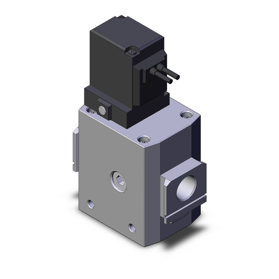
Soft Start-up Valve
MODEL / Series / Product Number
AV2000-(F,N)02(B,G,S)-1~6(G,D,Y,DO,YO)(Z)(B,C)(-R,Z)-A
AV3000-(F,N)03(B,G,S)-1~6(G,D,Y,DO,YO)(Z)(B,C)(-R,Z)-A
AV4000-(F,N)04(B,G,S)-1~6(G,D,Y,DO,YO)(Z)(B,C)(-R,Z)-A
AV5000-(F,N)06~10(B,G,S)-1~6(G,D,Y,DO,YO)(Z)(B,C)(-R,Z)-A
AVA2000-(F,N)02(B,G,S)(-R,Z)-A
AVA3000-(F,N)03(B,G,S)(-R,Z)-A
AVA4000-(F,N)04(B,G,S)(-R,Z)-A
AVA5000-(F,N)06~10(B,G,S)(-R,Z)-A
AVL2000-(F,N)02(B,G,S)-(1~6)(D,Y,DO,YO,WO)(Z)(-R,Z)-A
AVL3000-(F,N)02(B,G,S)-(1~6)(D,Y,DO,YO,WO)(Z)(-R,Z)-A
AVL4000-(F,N)02(B,G,S)-(1~6)(D,Y,DO,YO,WO)(Z)(-R,Z)-A
AVL5000-(F,N)06~10(B,G,S)-(1~6)(D,Y,DO,YO,WO)(Z)(-R,Z)-A
Advertisement
Table of Contents

Related Manuals for SMC Networks AV2000-02-1


Summary of Contents for SMC Networks AV2000-02-1
- Page 1 Doc. No. AV*-OMZ0091 PRODUCT NAME Soft Start-up Valve MODEL / Series / Product Number AV2000-(F,N)02(B,G,S)-1~6(G,D,Y,DO,YO)(Z)(B,C)(-R,Z)-A AV3000-(F,N)03(B,G,S)-1~6(G,D,Y,DO,YO)(Z)(B,C)(-R,Z)-A AV4000-(F,N)04(B,G,S)-1~6(G,D,Y,DO,YO)(Z)(B,C)(-R,Z)-A AV5000-(F,N)06~10(B,G,S)-1~6(G,D,Y,DO,YO)(Z)(B,C)(-R,Z)-A AVA2000-(F,N)02(B,G,S)(-R,Z)-A AVA3000-(F,N)03(B,G,S)(-R,Z)-A AVA4000-(F,N)04(B,G,S)(-R,Z)-A AVA5000-(F,N)06~10(B,G,S)(-R,Z)-A AVL2000-(F,N)02(B,G,S)-(1~6)(D,Y,DO,YO,WO)(Z)(-R,Z)-A AVL3000-(F,N)02(B,G,S)-(1~6)(D,Y,DO,YO,WO)(Z)(-R,Z)-A AVL4000-(F,N)02(B,G,S)-(1~6)(D,Y,DO,YO,WO)(Z)(-R,Z)-A AVL5000-(F,N)06~10(B,G,S)-(1~6)(D,Y,DO,YO,WO)(Z)(-R,Z)-A...
-
Page 2: Table Of Contents
Contents Page 1. Safety Instructions 2~14 2. Application 3. Specifications 15~16 4. How to Order 17~21 5. Construction / Parts List 22~23 6. Assembly of Optional Parts 7. Working Principle 8. Trouble Shooting 9. Disassembly Drawing 10. Dimensions 28~33... -
Page 3: Safety Instructions 2~14
These safety instructions are intended to prevent hazardous situations and/or equipment damage. These instructions indicate the level of potential hazard with the labels of “Caution,” “Warning” or “Danger.” They are all important notes for safety and must be followed in addition to International Standards (ISO/IEC) , and other safety regulations. - Page 4 Caution The product is provided for use in manufacturing industries. The product herein described is basically provided for peaceful use in manufacturing industries. If considering using the product in other industries, consult SMC beforehand and exchange specifications or a contract if necessary. If anything is unclear, contact your nearest sales branch.
- Page 5 Design Warning 1. Actuator operation When using solenoid valve or actuator in the outlet side of tis product, implement appropriate measures to prevent potential danger caused by actuator operation. 2. Holding pressure Since the valve might have slight internal leakage, it is not suitable for holding pressure in a tank or another vessel for a long period of time.
- Page 6 7. Operation for air blowing This product cannot be operated for air blowing due to the mechanism that switches the main valve to be fully open after the outlet side’s pressure (P ) increase to approximately 1/2 of the inlet side’s pressure (P Caution 1.
- Page 7 Adjustment Caution 1. Needle operation of low speed air supply To perform the initial speed adjustment of the outlet side actuator, supply air from this product’s inlet side and turn ON the pilot valve. Then, rotate the needle counterclockwise from the fully closed position. Product bottom surface (exhaust port side) Piping Warning...
- Page 8 5. F.R.L module combination When connecting to a modular F.R.L. combinations (AC20 to AC60), select one of the spacers from accessories. (Refer to page 23 for details.) However, modular combination with AC40-06 is not available. Forthermore, connect this product to the outlet side of the F.R.L. combination. Tighten the 2 holding screws on the spacer with bracket or spacer evently.
- Page 9 7. Inlet side piping conditions The normal size of the piping material’s or equipment’s bore should be equal to or larger than the port size of this product. The combine sonic conductance of the inlet side’s (P port side’s) piping or equipment shoule be equal to or larger than the values below. When the piping is restricted or the supply pressure is insufficient, the main valve will not switch and air leakage may occur from the R port.
- Page 10 Caution 1. Install an air filter Install an air filter of 5 µm or smaller filtration on upstream side. 2. Take measures to ensure air quality, such as by installing an aftercooler, air dryer, or water separator. Compressed air that contains a large amount of drainage can cause a malfunction of pneumatic equipment such as valves.
- Page 11 Manual Override Operation Warning ■ Push-turn locking slotted type [Type B] While pressing, turn it the direction of the arrow. It it is not turned, it can be operated the same way as the non-locking type. Locked position Caution When operating the locking type B with a screwdriver, turn it gently using a watchmaker’s screwdriver.
- Page 12 Surge Voltage Supperssor Caution <For DC> Grommet With light/surge voltage suppressor (GZ) ・Connect correctly the lead wires to + (positive) and – (negative) indications on the connector. ・Solenoids, whose lead wires have been pre- wired: positive side red and negative side black. DIN Terminal With light/surge voltage suppressor (DZ, YZ) ・DIN terminal has no polarity...
- Page 13 <For AC> Grommet With light (GZ) DIN Terminal With light (DZ, YZ) * Surge voltage suppressor of varistor has residual voltage corresponding to the protective element and rated voltage; therefore, protect the controller side from the surge. The residual voltage of the diode is approximately 1 V. How to Use DIN Terminal Connector Caution Connection...
- Page 14 Changing the entry direction After separating the terminal block and housing, the core entry can be changed by attaching the housing with 90 interval direction. Note that the direction cannot be changed towards this product. * When equipped with a light, be careful not to damage the light with the cord’s lead wires. Precautions Plug in and pull out the connector vertically without tilting to one side.
- Page 15 DIN Connector Part Nos. Caution <Type D> Without light SY100-61-1 SY100-61-1-C With light Part number Part number Rated voltage Voltage symbol (For AV) (For AVL) DC24V SY100-61-3-05 SY100-61-3-05-C DC12V SY100-61-3-06 SY100-61-3-06-C AC100V 100V SY100-61-2-01 SY100-61-2-01-C AC200V 200V SY100-61-2-02 SY100-61-2-02-C AC110V 110V SY100-61-2-03 SY100-61-2-03-C...
-
Page 16: Application
2. Applications This product is intended for use in circuits that require low speed air supply to gradually raise initial pressure in an air system and for quick exhaust by cutting off air supply when the control power is cut off in the event of a power failure or emergency. 3. - Page 17 Flow Rate Characteristics Series AV2000-A AV3000-A AV4000-A AV5000-A 1(P)・2(A) Port size 3(R) C [dm /(s・bar)] 13.1 19.2 34.8 41.3 1(P)→2(A) 0.36 0.27 0.32 0.66 0.34 12.6 13.7 Flow rate C [dm /(s・bar)] 10.1 23.7 characteristics 2(A)→3(R) 0.46 0.48 0.55 0.67 Pressure for switching from low speed Needle flow characteristics at low speed air supply air supply to rapid air supply...
- Page 18 4.How to Order AV 20 00 - 02 B – 1 D ❶ ❷ ❸ ❹ ❺ ❻ ❼ ❽ ❾ ❶ Symbol Description Body size ● ● ● ● ❷ Thread type ● ● ● ● ● ● ● ●...
- Page 19 AV A 20 00 - 02 B – ❶ ❷ ❸ ❹ ❺ Air operated type ❶ Symbol Description Body size ● ● ● ● ❷ ● ● ● ● Thread type ● ● ● ● + ● ― ― ―...
- Page 20 AV L 20 00 - 02 B Manual operation AV L 20 00 - 02 B – 1 D with solenoid valve ❶ ❺ ❻ ❼ ❽ ❷ ❸ ❹ Lockout type ❶ Symbol Description Body size ● ● ● ●...
-
Page 21: How To Order
How to Order of Pilot Valve Assembly AV 2 0 - 1 G ❶ ❷ ❸ ❹ ❺ Applicable size Symbol Description 2000 3000 4000 5000 AV2000-A, AV3000-A ● ● ― ― ❶ Body size AV4000-A, AV5000-A ― ― ● ●... - Page 22 AV L 2 0 - Manual operation AV L 2 0 - 1 G with solenoid valve ❶ ❷ ❸ ❹ Applicable size Symbol Description 2000 3000 4000 5000 ❶ ● ● ● ● Body size AVL2000 to 5000-A + ●...
-
Page 23: Construction / Parts List
5.Construction / Parts list Appearance Constructions Component Parts Description Material Body Aluminum die-cast Bottom cover Aluminum die-cast Top cover Aluminum die-cast Replacement Parts Description Material AV2000-A AV3000-A AV4000-A AV5000-A - Pilot valve assembly See below. See below. Valve assembly Rubber material: AV22P-060AS AV42P-060AS AV52P-060AS HNBR... - Page 24 Optional Parts Nos. Series AV2000-A AV3000-A AV4000-A AV5000-A Bracket Assembly AV22P-210AS AV32P-210AS AV42P-210AS AV52P-210AS Silencer Assembly AV22P-250AS AV32P-250AS AV42P-250AS AV52P-250AS Pressure gauge G36-10-□01 *1 Bracket: 1 pc., Mounting screw: 2 pcs. (3pcs for AV5000-A) *2 Element, Element O-ring, Element cover: 1 pc. For each *3 □...
-
Page 25: Assembly Of Optional Parts
6. Assembly of Optional parts (1) Bracket assembly 1) Installation of bracket Align two holes of the bracket with the holes at the bottom of the product. See drawing of the left. (3 holes for AV5000-A) 2) Tightening of screw Insert the mounting screw (cross recessed head screw with captive washer) to the holes of the product at the opposite side of the bracket, and... -
Page 26: Working Principle
7.Working Principle Internal construction/Cylinder actuation circuit Working Pressure Operation description Pilot valve (Meter-out control) example conditions conditions Operation description of the soft start-up valve When the pilot valve ① is energized or turned ON manually, the spool ② is pushed down due to the pilot air and gets into contact with the valve ③, closing the flow passage to port 3 (R). -
Page 27: Trouble Shooting
8. Trouble Shooting Power supply Phenomenon Cause Countermeasure of pilot valve Air leaks from 3 (R) port. 1. Inclusion of foreign matter onto sheet 1. Please air blow the sheet surface surface of the valve assembly. of the valve assembly. 2. -
Page 28: Disassembly Drawing
9.Disassembly drawing Pilot valve assembly Body Plug assembly Valve Top cover assembly Piston Valve assembly spring Piston spring Needle assembly Damper Bottom cover Control valve assembly -27-... -
Page 29: Dimensions
9.Dimensions Grommet: AV□00-□-□G□-□-A (mm) Body Coil size type Dimensions (mm) Standard specifications Model Port size 1(P) 2(A) 3(R) AV2000-□02-1 to 4G(Z)□-A Width across 24.5 flats 22 AV2000-□02-5 to 6G(Z)□-A AV3000-□03-1 to 4G(Z)□-A Width across 29.5 flats 24 AV3000-□03-5 to 6G(Z)□-A AV4000-□04-1 to 4G(Z)□-A Width across 39.5... - Page 30 DIN terminal: AV□00-□-□D/Y□-□-A Dimensions (mm) Standard specifications Model Port size 1(P) 2(A) 3(R) Width across AV2000-□02-1 to 6D/Y(Z)□-A 24.5 flats 22 Width across AV3000-□03-1 to 6D/Y(Z)□-A 29.5 flats 24 Width across AV4000-□04-1 to 6D/Y(Z)□-A 39.5 flats 30 Width across AV5000-□06,10-1 to 6D/Y(Z)□-A 3/4,1 3/4,1 flats 36...
- Page 31 Air operated type: AVA□00-□-□-A Dimensions (mm) Standard specifications Model Port size Pilot Port size 1(P) 2(A) 3(R) Width across AVA2000-□02-□-A 66 65.6 47 24.5 20 flats 22 Width across AVA3000-□03-□-A 76 65.6 50 29.5 20 flats 24 Width across AVA4000-□04-□-A 98 75.6 56 39.5 26 flats 30 Width across...
- Page 32 Lockout type (Manual operation): AVL□00-□-□-A (mm) Dimensions Standard specifications Model Port size 1(P) 2(A) 3(R) Width across AVL2000-□02-□-A 100.6 47 24.5 flats 22 Width across AVL3000-□03-□-A 100.6 50 29.5 flats 24 Width across AVL4000-□04-□-A 110.6 56 39.5 flats 30 Width across AVL5000-□06,10-□-A 3/4,1 3/4,1...
- Page 33 Lockout type (Manual operation with solenoid valve) DIN terminal:AV□00-□-□D/Y□-□-A (mm) Dimensions Standard specifications Model Port size E1 E2 1(P) 2(A) 3(R) Width across AVL2000-□02-1 to 6D/Y(Z)-□-A 66 119.5 47 24.5 20 48.9 90.3 flats 22 Width across AVL3000-□03-1 to 6D/Y(Z)-□-A 76 119.5 50 29.5 20 53.9 95.3 flats 24...
- Page 34 Lockout type (Manual operation with solenoid valve) M12 connector:AV□00-□-□WOZ-□-A (mm) Dimensions Standard specifications Model Port size D E1 1(P) 2(A) 3(R) Width across AVL2000-□02-5 to 6WOZ-□-A 66 108.1 47 24.5 20 74 90.3 flats 22 Width across AVL3000-□03-5 to 6WOZ-□-A 76 108.1 50 29.5 20 79 95.3 flats 24...
- Page 35 Revision history 4-14-1, Sotokanda, Chiyoda-ku, Tokyo 101-0021 JAPAN Tel: + 81 3 5207 8249 Fax: +81 3 5298 5362 https://www.smcworld.com Note: Specifications are subject to change without prior notice and any obligation on the part of the manufacturer. © 2019 SMC Corporation All Rights Reserved...
Need help?
Do you have a question about the AV2000-02-1 and is the answer not in the manual?
Questions and answers