
Related Manuals for SMC Networks AXTS040-2-X202 Series


Summary of Contents for SMC Networks AXTS040-2-X202 Series
- Page 1 Doc no.DOC1067657 NN65793200 PRODUCT NAME Pulse Blow Valve MODEL / Series / Product Number AXTS040□-2-X202...
-
Page 2: Table Of Contents
Contents Safety Instructions・・・・・・・・・・・・・・・・・・・・・・・・・・・・・・・・・ P2-3 Specifications ........................P4 Outline Dimensions ......................P4-5 Installation .......................... P6 Setting ..........................P7-8 Precautions of pulse blow valve ..................P9 Limitations of Use ......................P9-11 How to Order ........................P11 Maintenance ........................P11 Troubleshooting ........................ P12... -
Page 3: Safety Instructions・・・・・・・・・・・・・・・・・・・・・・・・・・・・・・・・・ P2-3
Safety Instructions These safety instructions are intended to prevent hazardous situations and/or equipment damage. These instructions indicate the level of potential hazard with the labels of “Caution,” “Warning” or “Danger.” They are all important notes for safety and must be followed in addition to International Standards (ISO/IEC) , and other safety regulations. - Page 4 Safety Instructions Caution We develop, design, and manufacture our products to be used for automatic control equipment, and provide them for peaceful use in manufacturing industries. Use in non-manufacturing industries is not covered. Products we manufacture and sell cannot be used for the purpose of transactions or certification specified in the Measurement Act.
-
Page 5: Specifications
1. Specifications Table 1 Specifications Model AXTS040□-2-X202 Type of actuation Internal pilot Valve construction Metal seal Fluid Operating pressure range 0.2 to 1.0MPa Frequency adjustment range 1 to 12Hz Proof pressure 1.5MPa Ambient and fluid temperature -5 to 50℃ (No freezing) Lubrication Weight About 1,400g... - Page 6 Fig.2 Pneumatic Symbols...
-
Page 7: Installation
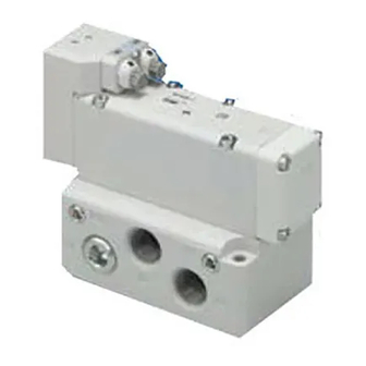
3. Installation 2(B): OUT port 3(R2): IN port Port size: 1/2 Port size: 1/2 Silencer A Silencer B Pilot plate During installation of this product, do not cover this face. Fig. 3 Appearance and piping ports of pulse blow valve When air is supplied to the IN port, pulse air is generated from the OUT port. -
Page 8: Setting
4. Setting Continuous air blow can be changed to pulse blow without electrical wiring by installing this product between the continuous air blow valve and nozzle of existing equipment. By means of adjustment needle, it is possible to individually adjust the pulse blow ON and OFF times (frequency). - Page 9 Relationship between Frequency and Percentage of ON time Relationship between Frequency and Percentage of ON time (ON,OFF)=(8,8) OFF : 7 ON : 7 OFF : 6 ON : 6 ON indicator OFF : 5 ON : 5 OFF indicator OFF : 4 ON : 4 OFF : 3 ON : 3...
-
Page 10: Precautions Of Pulse Blow Valve
5. Precautions of pulse blow valve This pulse blow valve has a large effective area and is capable of achieving high flow rates. To effectively use the pulse blow valve, it is recommended that a nozzle with a diameter of φ4 or more is installed downstream or ensure an effective area equivalent to or larger than a φ4 nozzle by using multiple nozzles. - Page 11 4) Locations subject to vibration or impact. 5) Locations where radiated heat will be received from nearby heat sources. Air Supply 1) Install a filter to use clean fluid. (Recommended filtration rating: 5 μm or less.) If you use fluid mixed with foreign matter, issues such as operation failure may occur due to adhesion of the foreign matter on the sliding part.
-
Page 12: How To Order
Lubrication 1) The sliding parts of this product are lubricated. Be aware that due to the construction, some lubricant may flow out to the outlet side with the blow air. 2) These valves can be used without lubrication. 3) If a lubricant is used in the system, use class 1 turbine oil (no additives) ISO VG32 or class 2 turbine oil (with additives) ISO VG32. -
Page 13: Troubleshooting
9.Troubleshooting 1) Operation frequency is slow, or air blow pressure has reduced. Check whether use of this pulse blow valve or other pneumatic equipment has caused the pressure to drop in the air pressure line. Also confirm that the pressure at the time of opening of the valve is equal to or greater than the lower limit of the operating pressure range of the product (0.2 MPa). - Page 14 Revision history Tel: + 81 3 5207 8249 Fax: +81 3 5298 5362 https://www.smcworld.com Note: Specifications are subject to change without prior notice and any obligation on the part of the manufacturer. © SMC Corporation All Rights Reserved...
Need help?
Do you have a question about the AXTS040-2-X202 Series and is the answer not in the manual?
Questions and answers