Table of Contents
Advertisement
Advertisement
Table of Contents

Subscribe to Our Youtube Channel
Related Manuals for Morita veraviewepocs 2d


Summary of Contents for Morita veraviewepocs 2d
- Page 1 2022-02-21 Pub. No.: X7C0-91001-503 (EN) Printed in Japan...
-
Page 2: Table Of Contents
Table of Contents Prevent Accidents ............................. 1 For Safe Operation ........................... 3 Parts Identification ..........................6 (I) Parts Identification ............................6 (II) Patient Frame and Arm Operation Panels ...................... 9 (III) Parts of Device ............................. 13 (IV) Patient Positioning Tools and Consumable Parts ..................13 Operation .............................. - Page 3 This manual covers a fully equipped model; refer to the sections covering the instruments and functions of your own unit. Thank you for purchasing the Veraviewepocs 2D. For optimum performance and safety, read this manual thoroughly before using the equipment.
-
Page 5: Prevent Accidents
Do not fail to send the manufacturer’s copy to J. MORITA MFG. CORP. SAFETY INSTRUCTIONS AND RECORDING INFORMATION When the Veraviewepocs 2D is installed, the installer or other responsible party must explain the precautions and usages in the Instructions for Use to the user and the person responsible for maintenance and management. - Page 6 (7) Fires, earthquakes, floods, lightning, natural disasters, or acts of God. • The useful life of the Veraviewepocs 2D is 10 years from the date of installation provided it is regularly and properly inspected and maintained.
-
Page 7: For Safe Operation
4. Routers for intra-building paging systems, wireless LAN, cordless analogue telephones, and other electric wireless devices. • Interference from the Veraviewepocs 2D, devices listed below might malfunction or operate in a random, unexpected and dangerous manner. 1. Electrical diagnostic, examination or treatment devices. - Page 8 • Watch the area around the moving parts to avoid collision against the body parts or other objects which may result in injury. • The EQUIPMENT should not be used adjacent to or stacked with other equipment and that if adjacent or stacked use is necessary, the EQUIPMENT should be observed to verify normal operation in the configuration in which it will be used.
- Page 9 • Always try to maintain contact with the patient visually and auditorily to ensure safe operation of the unit.
-
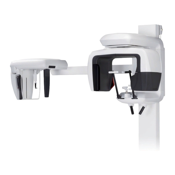
Page 10: Parts Identification
Parts Identification (I) Parts Identification Main Unit Mirror Lift Cephalo Unit (Option) Operation Panel Cassette Holder Temple Stabilizer X-ray Head Chin Rest Panorama Models (models without cephalo unit) Patient Frame X-ray Detector (built-in type) Support Column Base Models with Cephalo Unit or Cephalo Upgradable Models X-ray Detector (PAN/CEPH cassette)... - Page 11 Control box Emission Button Emission LED (yellow) Hand Switch Ready LED (green) Main LED (blue) Patient Frame Mid-sagittal Beam Auto Positioning Beam Frankfort Plane Beam Main Switch Frankfort Plane Beam Up/Down Knob Auto Positioning (AF) Sensor Beam Up/Down Knob Emergency Switch Liquid Crystal Display Image Layer Beam Frame Operation Panel...
- Page 12 Cephalo Unit (Option) Nasion Plate Cephalo Operation Panel Craniostat Ear Rods Patient Guard Secondary Slit Frankfort Plane Beam Cassette Holder Ear Rods Plate...
-
Page 13: (Ii) Patient Frame And Arm Operation Panels
(II) Patient Frame and Arm Operation Panels Patient Frame Operation Panel Ready Key Before the Ready key is pressed, the green LED for it will be blinking on and off. Press the Ready key in order to complete patient positioning. The arm will rotate slightly and the positioning beams will light up. Pressing the Ready key also enables X-ray emission. - Page 14 Beam On/Off Keys Positioning beams automatically go off after 3 minutes. Press either one of these keys to turn them back on. Or press one of them to turn the beams off. Incisal Occlusion Key This key is used to make a panorama exposure for a patient with standard occlusion biting on a mouthpiece. After adjusting the height of the positioning (AF) sensor, press this key to automatically move the arm backwards or forwards to the optimum position.
- Page 15 Arm Operation Panel Usage Note ♦ Do not press down with excessive force on any of the operation panels. Do not press on the panels with any sharp objects like ballpoint pens or fingernails etc. 3, 4 Panorama Exposure Keys Use these keys to make various settings for panorama exposures.
- Page 16 X-ray Emission Keys Use the X-ray Emission keys (Auto Level, kV, and mA key) and Up/Down keys to set X-ray emission conditions. Auto Level key Up key kV key Down key mA key Auto and Manual Emission Keys For auto exposures, press Auto Level key and confirm that the corresponding LED lights up. For manual exposures, press kV key or mA key and confirm that the corresponding LED lights up.
-
Page 17: (Iii) Parts Of Device
(III) Parts of Device • Panorama & Cephalo (PAN/CEPH) Cassette (1) (Only for models with the cephalo unit, or cephalo upgradable models.) (IV) Patient Positioning Tools and Consumable Parts • Chin Rest (1) • Lip-nose Rest (1) • Mouthpieces (1 Box of 50) •... -
Page 18: Operation
Operation * If an accident occurs, the equipment must not be used until repairs have been completed by a qualified and trained technician authorized by the manufacturer. * Have patients remove glasses, necklaces, earrings and other accessories which could interfere with diagnosis. * If the unit has not been used for some time, make sure it operates normally and safely before use. -
Page 19: (I) Preliminary Procedures
(I) Preliminary Procedures Turn the computer on and start the application software to receive the image data read-in. <For the i-Dixel application> The i-Dixel application will start up automatically. Select and display the Patient Page and then make the exposure. (For new patients, first register the patient and then display the Select new Patient Page.) The exposure will be automatically... - Page 20 Check Panorama Operation Insert the PAN/CEPH cassette into the cassette holder and press the Dental Arch key.* Press the Ready key to enable X-ray emission. Hold down the emission button and check that the arm rotates, X-rays are emitted, the X-ray emission LED lights up, and the audible signal sounds.
-
Page 21: (Ii) Operation Procedures
(II) Operation Procedures Safety Check For safety, keep fingers away from moving parts when they are moved. Keep fingers away from gaps and openings for moving parts such as the cassette and its holder and the temple stabilizers as well as the holes on the support column for threaded bolts. -
Page 22: Panorama Exposures
Panorama Exposure. If the unit cannot be returned to a safe condition or will not operate, contact your local dealer or J. MORITA OFFICE. The image will be lost if the Emergency Stop Switch is pressed during its transmission or if the main switch is turned off. -
Page 23: Cassette Insertion
Panorama Exposures (2) Cassette Insertion Insert the PAN/CEPH cassette. * This procedure is not required for panorama models since the built-in X-ray detector is used with those models. 1. Hold the cassette with handle towards the front. Use the other Handle hand to support the bottom of the cassette and gently slide the cassette into the holder. - Page 24 Panorama Exposures • Do not bump, jiggle, vibrate or use excessive force. • Use both hands to put the cassette in and take it out. The cassette weights about 2 kg, and it could injure your foot if you dropped it. The sensor would also be damaged.
- Page 25 Panorama Exposures LED Color and Condition Green: Normal. Amber On: For X-ray emission and image transmission. Red Bllinking: Abnormal. Transmission malfunction. Cannot make exposure. Off: Power is off or cassette is not properly inserted. Slide the cassette all the way into the holder and make sure it is locked into place.
-
Page 26: Panorama Settings
Panorama Exposures (3) Panorama Settings When the unit is turned on, the operation panel is set to the factory defaults shown in the photo to the left. (3)-1. Auto Exposure (Digital Direct Auto Exposure) For auto exposure, the X-ray dosage is monitored and adjusted in real time depending on the patient’s anatomy and the selected exposure region. -
Page 27: Manual Exposure
Panorama Exposures (3)-2. Manual Exposure Press the kV or mA key to switch to manual exposure. Press the kV key to display the tube voltage value. This value can be changed. Use the Up and Down keys to increase or decrease the value. -
Page 28: Partial Panorama
Panorama Exposures (3)-4. Partial Panorama Partial panorama function divides a panoramic image into five areas and only selected areas will be exposed to reduce the X-ray dose. Right-click the resolution icon in the task tray. Select “Show DixelD dialog” from the shortcut menu. * If “Show DixelD dialog”... -
Page 29: Patient Positioning
Panorama Exposures (4) Patient Positioning Press the Ready key. The arm will automatically move into position for patient positioning. The green Ready LED will stop blinking and stay on. The Frankfort plane, Mid-sagittal, Image layer and AF beams will light up. Usage Note ♦... - Page 30 Panorama Exposures Chin Rest Positioning 1. <Initial Patient Positioning> Line up the center of the mouthpiece Put an X-ray protection apron on the patient. Have the with the center of the upper and patient perform the incisal occlusion while biting on an lower incisors.
- Page 31 Panorama Exposures Take care that the temple stabilizers do not strike the patient in the eye. • Do not use excessive force to close the temple stabilizers. This could be uncomfortable for the patient or damage the stabilizers. • Forcing the patient in or out could also damage the stabilizers.
- Page 32 Panorama Exposures Temple Stabilizer 6. Move the patient’s head to the left or right until the Mid-sagittal Mid-sagittal beam lines up with the patient’s mid-sagittal Heam plane. Then tighten up the temple stabilizer so that the patient’s face will not move. 7-1.
- Page 33 Panorama Exposures Press the Incisal Occlusion Key, which is used for auto Image Layer Value positioning with the mouthpiece. The arm (and the Image layer beam) will move to line the image layer up with the patient, and the value of the image layer will be displayed.
- Page 34 Panorama Exposures 7-2. <Manual Positioning> Use the Backward and Forward keys to line the Image layer beam up with the distal side of the patient’s upper, left canine. CLASS 2 LASER PRODUCT: A class 2 laser is used for the positioning beams. Image layer Beam The laser beams could damage the eyes.
- Page 35 Panorama Exposures Bite Block Positioning (Option) * Some part of the bite block will appear in the image. 1. Replace the chin rest with the bite block. Put a cover on the bite block. 2. Have the patient put on an X-ray protection apron. Open the temple stabilizers and have the patient step up to the unit.
- Page 36 Panorama Exposures Temple Stabilizer 4. Have the patient stand straight, move forward and lightly take the bite block in his mouth and then set his chin on it. Have him grip the handles and lower his shoulders. Close the temple stabilizers until they lightly contact the patient’s head.
- Page 37 Panorama Exposures 7. Use the Backward and Forward keys to line the Image layer beam up with the distal side of the patient’s upper, left canine. The laser beam could cause eye damage. Do not look Image Layer Beam directly into it or let it strike you or the patient in the eye. * Depending on the shape of the patient’s face, the Image layer beam may not directly strike the distal side of the upper left canine.
- Page 38 Panorama Exposures Usage Note ♦ If the patient is not properly positioned the image may not be useful for diagnosis. Refer to the examples below to better understand proper patient positioning. 7-3. <Examples of Patient Positioning and Image Results> Correct Positioning Patient Looking Down V-shaped Dental Arch Patient Looking Up...
- Page 39 , press the Ready key again to return the unit to its normal Ready setting and re-position the patient. The Double-Ready function is not enabled by default. To enable the Double-Ready function, contact your local dealer or J. MORITA OFFICE.
-
Page 40: Panorama Exposures
Panorama Exposures (5) Panorama Exposures 1. Make sure the green Ready LED is on; check the arm, patient frame or control box. Ready LED 2. Pick up the handswitch and hold down the emission button. The arm will start to rotate and X-rays will be emitted. Emission Button During X-ray emission, the yellow Emission LED on the control box will light up and an audible signal will sound. - Page 41 Panorama Exposures • Always leave the X-ray booth, and press the emission button outside of it. • In case of an emergency, release the emission button; this will completely stop the unit. • Warn the patient not to move during emission (while the melody is sounding).
-
Page 42: Patient Egress And Image Transmission
Panorama Exposures (6) Patient Egress and Image Transmission 1. <Patient Egress> After the exposure, the arm will automatically go to the patient egress position, 90 degrees. Open the temple stabilizers all the way up and guide the patient away from the unit. Then close the stabilizers all the way. - Page 43 Panorama Exposures During image transmission, a message will appear in the computer monitor screen. Then a progress bar will appear while the panorama image is being reconstructed. The image will appear after a few seconds. • Do not turn off the main switch until image transmission has completed and the panorama image is displayed.
- Page 44 Panorama Exposures * Software density compensation is applied to create the optimum image. However, if some areas of the image are exceptionally dark, the density compensation will tend to make the entire image whiter than usual. * For an enlarged digital image, there is a junction line that is not visible when the image is displayed initially. However, if the image is magnified, it appears as a fine, horizontal line through the center of the image.
-
Page 45: Exposure Regions
Panorama Exposures (7) Exposure Regions (7)-1. Panorama 1. Press the Dental Arch key. 2. Press either the adult or the child key. For a Pedodontic panorama, the arm’s angle of rotation and exposure range are reduced; the X-ray dosage is also reduced by from 10% to 15%. - Page 46 Panorama Exposures a. Standard Panorama Projection Very good for making measurements for implants etc. Press the Standard Projection Key. Standard Panorama Projection b. Shadow Reduction Projection Reduces shadows obscuring the mandibular ramus. Press the Shadow Reduction Key. Shadow Reduction Projection c.
-
Page 47: Maxillary Sinus (Posterior) (Mag.: 1.5×, Throughout)
Panorama Exposures (7)-2. Maxillary Sinus (posterior) (Mag.: 1.5×, throughout) [To examine the posterior maxillary sinus or facial injuries.] Press the Maxillary sinus key. Maxillary Sinus Panorama... - Page 48 Panorama Exposures Chin Rest Position Put the chin rest in the lowest position to make a maxillary sinus exposure. Low Groove * If, for children or short people, the AF sensor beam does not strike the mouthpiece even when it is at its lowest setting, set Medium Groove the chinrest at its Medium position.
-
Page 49: Tmj Quadruple (Mag.: 1.3× , Throughout)
Panorama Exposures (7)-3. TMJ Quadruple (Mag.: 1.3× , throughout) Press the TMJ key. Press either the Adult key or the Child key. Estimated Distance between Joints Adult : 100mm Child : 90mm Thickness : 10.5mm Length : 54mm Select the size best for the patient. Four images will appear in the computer display: one each for the mouth open and closed on both sides. - Page 50 Panorama Exposures Patient Positioning 1. Replace the chin rest with the lip-nose rest set at medium Lip-nose Rest height. Chin Rest Chin Rest Holder 2. Put an X-ray protection apron on the patient and stand in front of the lip-nose rest. Look at him from the side, and have him pull in his chin and straighten his back.
- Page 51 Panorama Exposures 4. Use the knob to open the temple stabilizers. Have the patient move forward without slouching or otherwise changing his posture. Then have him put his upper lip on the lip-nose rest and lightly grip the patient handles. Make sure his shoulders are lowered.
- Page 52 , press the Ready key again to return the unit to its normal Ready setting and re-position the patient. The Double-Ready function is not enabled by default. To enable the Double-Ready function, contact your local dealer or J. MORITA OFFICE.
- Page 53 Panorama Exposures Open and Closed Mouth Exposures Check that the Ready LED (green) on the patient frame, operation panel, or control box is on. Ready LED Mouth Closed Exposure (First Exposure) 1. Pick up the handswitch and hold down the emission button. Emission Button The arm will go to its starting position, start to rotate and exposures will be made of the left and right sides.
- Page 54 Panorama Exposures Open Mouth Exposure (Second Exposure) 1. Have the patient open their mouth. Emission Button 2. Pick up the handswitch and hold down the emission button. Emission LED The arm will start to rotate and exposures will be made of the left and right sides.
-
Page 55: Removing The Digital Cassette
Panorama Exposures (8) Removing the Digital Cassette * This procedure is not required for panorama models since the built-in X-ray detector is used with those models. * Make sure the green LED on the cassette is either blinking or out. 1. -
Page 56: Cephalo Exposures (Option)
Cephalo Exposures Cephalo Exposures (option) (1) Turn Main switch On 1. Press the top ( | ) of the main switch. The blue main LED will light up to show that the unit is on. Main LED 2. Press either the LA (Lateral) or PA (posteroanterior) key to set the unit for cephalo exposure. -
Page 57: Emergency Stop Switch
Panorama Exposure. If the unit cannot be returned to a safe condition or will not operate, contact your local dealer or J. MORITA OFFICE. The image will be lost if the Emergency Stop Switch is pressed during its transmission or if the main switch is turned off. -
Page 58: Cassette Insertion
Cephalo Exposures (2) Cassette Insertion * Insert the PAN/CEPH cassette, used for both panorama and cephalo exposures. 1. Press the Cephalo Start Position Key. Both the cassette holder and the secondary slit plate will move forward. Cassette Holder Secondary Slit Plane Handle 2. - Page 59 Cephalo Exposures 4. Slide the cassette all the way in until the rod goes into its hole inside the holder. The rod will make and audible click and the button will pop out. A beep will also sound. After a few seconds the green LED on the cassette will start to blink on and off.
-
Page 60: La (Lateral) Exposure
Cephalo Exposures (3) LA (Lateral) Exposure Press the LA key. 2. Turn the Dens Comp key on to select both the required soft and hard tissues for making cephalo measurements. (Dens Comp: automatic density compensation) * When the Dens Comp key is turned on, the arm operation panel will display “90 kV.”... -
Page 61: Patient Positioning
Cephalo Exposures (4) Patient Positioning 1. Use the Up or Down key to raise or lower the craniostat Lift Up Key Lift Down Key match the patient’s height. Release the key to stop the craniostat moving. Usage Note ♦ The craniostat Up and Down keys will not work if the unit is not set for cephalo and the Ready key has not been pressed to turn the X-ray head in the cephalo direction. - Page 62 Cephalo Exposures 3. Grip the ear rod plates with both hands and open them up all the way. Ear Rod plate 4. Make it easy for the patient to take his place by raising the nasion plate and moving it out. 5.
- Page 63 Cephalo Exposures 7. With the Up or Down key, raise or lower the craniostat until the ear rods line up with the patient’s outer ear orifice and then release the key. Ear Rod 8. Grip the ear rod plates with both hands and carefully close them until the ear rods go into the patient’s ears.
- Page 64 Cephalo Exposures 10. After making sure the mid-sagittal and Frankfort plane Mid-sagittal Plane beams are lined up and the ear rods are in place, press the Start Position Key. Never let the patient hold onto the patient guard; his Frankfort Plane fingers could be pinched between it and the cassette holder causing an injury.
-
Page 65: X-Ray Emission
Cephalo Exposures (5) X-ray emission 1. Check the arm operation panel, patient frame or control box, and make sure the green Ready LED is on. Ready LED 2. Pick up the handswitch and hold down the emission button. Emission Button After a few seconds the secondary slit and cassette holder will start to move and X-rays will be emitted. - Page 66 Cephalo Exposures 3. Keep holding the emission button down. When the exposure is finished, the cassette holder and secondary slit plate will stop moving and X-ray emission will also stop. The Emission LED will go out, and the audible signal will stop. Now release the emission button.
-
Page 67: Patient Egress And Image Transmission
Cephalo Exposures (6) Patient Egress and Image Transmission 1. Use both hands to carefully open the ear rod plates and get the ear rods out of the patient’s ears. Open the ear rod plates very carefully and make sure the ear rods are well clear of the patient’s ears;... - Page 68 Cephalo Exposures * Software density compensation is applied to create the optimum image. However, if some areas of the image are exceptionally dark, the density compensation will tend to make the entire image whiter than usual. * For an enlarged digital image, there are junction lines that are not visible when the image is displayed initially. However, if the image is magnified, they appear as fine, horizontal lines dividing the image in thirds.
-
Page 69: Pa (Posteroanterior) Exposure
Cephalo Exposures (7) PA (posteroanterior) Exposure 1. Press the PA key. 2. Turn the Dens Comp key on to select both the required soft and hard tissues for making cephalo measurements. (Dens Comp: automatic density compensation) (Soft tissues will not be selected if the Dens Comp key is turned off.) * When the Dens Comp key is turned on, the arm operation panel will display “90 kV.”... - Page 70 Cephalo Exposures 45 Degree Slant Exposure Set the craniostat at a 45 degree angle to either the right or left. Set the unit for a PA Exposure. Hand Exposure 1. Select PA Exposure. 2. Turn the Density Compensation off. 3. Set tube current for 1 mA. * 90 kV and 1 mA are rough estimates for a child, but mA can be adjusted depending on the patient’s size.
- Page 71 Cephalo Exposures 6. Have the patient place his hand inside the rectangle on the Hand X-ray Plate. • Make sure nothing other than the patient’s hand is inside the rectangle on the Hand X-ray Plate. • Do not fail to take the Hand X-ray Plate off after completing the exposure.
-
Page 72: Removing The Digital Cassette
Cephalo Exposures (8) Removing the Digital Cassette * Make sure the green LED on the cassette is either blinking or out. 1. Support the cassette holder with one hand and press the Button release button. Pull the cassette out a little and then release the button. -
Page 73: Calibrating Digital Cephalo Data For Software Analysis
CEPH Calibrating Digital Cephalo Data for Software Analysis Digital cephalo data must be calibrated for whatever analysis software you are using. Measurements will not be correct if the data is not calibrated. * Cephalo image data has a resolution of 176 dpi. * Refer to the user’s manual for your analysis software for instruction on how to calibrate the data. -
Page 74: (Iii) After Use
Cephalo Exposures (III) After Use Turn Main switch Off Press the bottom ( ○ ) of the main switch to turn it off. The main LED will go out. Do not fail to turn the unit off after use; this will eliminate the risk of electrical leakage and accidents. -
Page 75: Maintenance, Parts Replacements, And Storage
• Replace the parts listed in the Regular Inspection List as necessary depending on degree of wear and length of use. For details, see page 75 “Service Life, Consumables, and Replacement Parts”. • Order replacement parts from your local dealer or J. MORITA OFFICE. (III) Storage •... -
Page 76: Regular Inspection
• The inspection items marked * may only be performed by the service personnel for furether preventive inspection and maintenance during the life of the device. • For repair or other types of service contanct your local dealer or J. MORITA OFFICE. Regular Inspection List Power Supply and Physical Stability 1. - Page 77 13. Temple stabilizers and chinrest Turn the temple stabilizer knob to make sure the stabilizers open and close properly. Make sure the chinrest and lip-nose rest are secure in both their upper and lower positions. 14. Lift Mechanism Press the up and down keys. Make sure the lift moves smoothly and stops properly.
- Page 78 Cephalo Exposure 1. X-ray Head changeover Close the panorama temple stabilizers. Press either LA or PA cephalo and then the Ready key. Make sure the X-ray head turns around and that it and the arm automatically go into their cephalo positions. Make the above operation is not performed when the panorama temple stabilizers are open even if the cephalo and Ready keys are pressed.
-
Page 79: Service Life, Consumables, And Replacement Parts
However, if a maintenance contract has been agreed to, this will depend on the contents of that contract. For details concerning regular inspection and parts replacements, contact your local dealer or J. MORITA OFFICE. Component Service Life List... - Page 80 • Independent technicians specially trained and authorized by J. MORITA. The circuit diagrams, component parts lists, descriptions, calibration instructions, or other information will be available on request, only for the service personnel authorized by J. MORITA to repair those parts.
-
Page 81: Trouble Shooting
♦ Before conducting the inspection or adjustment, confirm that the Main LED (blue) on the control box is lit. ♦ Contact your local dealer or J. MORITA OFFICE for repairs if the apparatus does not work normally even after performing the steps recommended below. - Page 82 Computer Screen and Arm Display Problem Possible Cause Remedy Warning Messages LAN cable transmission problem In computer screen for CT images * LAN cable is not properly Reconnect and confirm LAN connected. cable connection. Restart i-Dixel application. (for CT exposure) In X-ray unit Arm Display The computer is not receiving the image.
- Page 83 Computer Screen and Arm Display Problem Possible Cause Remedy Warning Messages In computer screen ・ Close the message in the computer monitor and select a patient page. Exposure was initiated ・ Press the Ready key and without selecting a patient then repeat the Ready page.
- Page 84 Exposures and Main Unit Problem Possible Cause Remedy Turn unit off. Make sure of patient and user safety. Turn Panorama & Cephalo unit back on and see if it works normally. • Image too light Make sure that the power supply is AC 108 to 132 V •...
- Page 85 Exposures and Main Unit Problem Possible Cause Remedy • LCD goes out. • Weird characters in • Error message in Turn unit off. Make sure of patient and user safety. Turn unit back on and see if it works normally. •...
- Page 86 Messages appear in the Arm Display when anomalies are detected. Respond according to the error message number as explained in the following chart. If this does not solve the problem, contact your local dealer or J. MORITA OFFICE. Make a note of the error number and report it when requesting help for the company. Message...
- Page 87 Patient positioning operation is the unit off, wait about one minute and suspended for safety. then turn it back on. Contact your local dealer or J. MORITA No analog power given to the imaging module. OFFICE. HOLIZONTAL BEAM did not return to its...
- Page 88 Unable to establish connection with the PC. System will not be able to receive images properly. Contact your local dealer or Do not continue to use the unit in this state. J. MORITA OFFICE. Contact your J.MORITA Service Center/Distributor to restore the setting."...
- Page 89 Message Possible Cause Remedy Contact your local dealer of J. MORITA Arm motor is not moving OFFICE. to have the unit inspected and repaired. The error occurred between equipment and Turn off, wait 1 minute, turn back on application software.
- Page 90 <Cable Routing Diagram> Cable connections and routing may differ depending on the model. LAN Cables LAN Board A On back of X550 Cephalo only HUB 2 For X550 Capture PC...
-
Page 91: Ddae Verification Procedure
DDAE Verification Procedure 1. DDAE Verification DDAE (Digital Direct Auto Exposure) is verified by this procedure. 1) DDAE Verification Flowchart Start ↓ Set the test pieces ↓ Setup i-Dixel ↓ Make a panorama scan ↓ Check DAP value ↓ Switch the test piece ↓... - Page 92 2. Setup 1) Test Piece (Option) DDAE verification uses copper plates attached to Veraviewepocs. Test copper piece consists of three copper plates (1), (2), (3) 2) Set the Test Pieces 2)-1 Remove the chin rest and close the temple stabilizers. Temple Stabilizers 2)-2 Set the Test Piece as shown below.
- Page 93 3) Setup i-Dixel 3)-1 Startup i-Dixel 3)-2 To add "Additional Information" in the Tool Panel if it is not shown, go to "Home Menu" and open "Settings Window" by clicking the screw wrench button at the bottom. 3)-3 Open Tool Panel tab and select "Additional information" Available buttons box on the left. Then, click "Add >>".
- Page 94 3. Make exposure 1) Startup 1)-1 Open a patient for the test. 1)-2 Turn on the Veraviewepocs. 2) Make a panorama exposure 2)-1 Set the copper plate (1) + (2). Two plates are to be in the X-ray field. 2)-2 Make a Panorama exposure with Auto Exposure Level "0". 2)-3 Check DAP Value After the exposure, check the Additional information.
- Page 95 Verification Procedure 1) Compare the DAP values from the previous two scans; scan with the copper plate (1) and with the copper plate (1) + (2). 2) Check if the value with the copper plate (1) + (2) is greater than the one with the copper plate (1). 3) Use the following flowchart to verify the DDAE.
-
Page 96: Technical Specifications
Technical Specifications (I) Specifications Product Name Veraviewepocs Model X550 Type EX-1 / EX-2 Classification Protection against electric shock Class I, Type B Type B applied parts Temple Stabilizers, Ear Rods, Chin Rest, Bite Block, Bite Plate, Nasion Plate, Hand X-ray Plate, Lip-nose Rest, Patient Handles (non-conductive connection to patient) Protection against ingress of liquids IPX0... - Page 97 X-ray Tube Head Assembly with High Voltage Generator Tube D-051 Focal Spot Target Angle 5º Target Material Tungsten Filtration Inherent filtration minimum 2.5 mm Al, 75 kV/HVL 3.5 mm AL (X-ray tube filtration: 0.8 mm Al, Al filter: 1.7 mm) Beam Quality HVL minimum 2.9 mm AI at 80 kV HVL minimum 3.2 mm AI at 90 kV...
- Page 98 TMJ Quadruple (2/4 images): High resolution Super high resolution Patient size Mode Mode Adult / 4.3s 8.6s Pedodontic Cephalometric: Direction Lateral Dens Comp. ON 4.9 s 4.1 s Dens Comp. OFF 3.5 s 5.0 s Accuracy of displayed values: ± (5 % + 50 ms) (* Registered value for FDA is ± 10 %) Test instruction of X-ray tube voltage, current, and exposure time Constant (manual) exposure mode Reproducibility of air karma Coefficient of variation max.
- Page 99 Power Requirements EX-1 EX-2 Input Voltage AC120 V AC 220/230/240 V 60 Hz single phase 50-60 Hz single phase Line Voltage regulation Max. 8 % Max. 8 % Range of line voltage 108 to 132 V AC 220/230/240 V ± 10 % (Including Line voltage (Including Line voltage regulation)
- Page 100 Vertical Height of Focal Spot 1,055 to 1,775 mm (Panoramic) 970 to 1,605 mm (Option) 1,125 to 1,775 mm (with Cephalometric, Upgradable Cephalometric) 1,040 to 1,605 mm (Option) Patient Positioning Auto focus using light sensor for distance measurement and electrically operated positioning system Patient Positioning Beam Class 2 Laser.
- Page 101 Image Quality Panoramic: Line pair resolution 2.5 LP/mm Low contrast resolution diameter 2.0mm Cephalometric: Line pair resolution 2.5 LP/mm Low contrast resolution diameter 2.5mm X-ray Dose Information The following image information is recorded for each exposure. ▪ Dose Area Product (DAP) (mGy × cm2) ▪...
- Page 102 Everybody who connects additional equipment to the signal input part or signal output part configures a medical system, and is therefore responsible that the system complies with the requirements of IEC 60601-1. If in doubt, consult the nearest J. MORITA OFFICE, its representative or its dealer for help.
- Page 103 Related C-UL standard (addition to Canada) Local regulations Application Software Application software for image processing or data base is provided by J. MORITA OFFICE. It shall be used with above Windows based computer specifications. It conforms to 93/42/EEC (in EU), IEC62304 and 21 CFR (in USA), Medical device regulations (in Canada).
- Page 104 Please inquire of the local city/community administrations concerning local disposal companies. This symbol indicates that the waste of electrical and electronic equipment must not be disposed as unsorted municipal waste and must be collected separately. Contact your local dealer or J. MORITA OFFICE for details.
- Page 105 Tube Housing Assembly Heating Curve (kJ) 210 240 (min) Tube Housing Assembly Cooling Curve (kJ) (min)
- Page 106 Tube Rating Chart Tube rating chart Maximum Rating Chart (Absolute Maximum Rating Charts) D-051 Focal Spot: 0.5mm 70kV 80kV 60kV 50kV 90kV 100kV EXPOSURE TIME (s) Anode Thermal Characteristics Anode Thermal Characteristics D-051 280W 230W 170W COOLING HEATING TIME (min)
- Page 107 Reference Axis Panoramic Cephalometric...
-
Page 108: (Ii) Symbols And Markings
(II) Symbols and Markings * Some symbols may not be used. Laser Radiation Caution Label (EX-1) Laser Caution Label (EX-1) Caution Label (EX-2) Laser Caution Label (EX-1) Laser Caution Label (EX-2) Tube Label Type B Applied Part Rating Label Type Label (EX-1) Caution Label (EX-1) Equipotentiality (EX-2) - Page 109 Laser Radiation Laser Caution Label (EX-1) Laser Caution Label (EX-1) Laser Caution Label (EX-2) Warning Label (EX-1) X-ray Warning Symbol and Statements (EX-1) Main Switch ⃒: On ⃝: Off Emergency Stop Caution Label (EX-1) Focal Spot (dimple) Audible Signal Caution Label (EX-2) and Accuracy Label (EX-1)
- Page 110 Package This way up Fragile Keep away from rain Temperature limitation Humidity limitation Atmospheric pressure limitation Attention, consult accompany Do not reuse documents Prescription Device CAUTION: Federal law restricts this device to sale by or on the order of a dentist and a licensed healthcare practitioner.
- Page 111 Indicated Items on the Rating Label and X-ray Tube Head Assembly Label * For details, refer to “Technical Specifications” (p. 92). * Some symbols described on the previous page may be included. Rating Label Model: Model of X-ray system Type: Type Input: Rated input voltage, frequency, and power in operation Standby: Input power in standby Duty Cycle: Duty cycle of X-ray system...
-
Page 112: Electromagnetic Disturbances (Emd)
EMD information provided in the ACCOMPANYING DOCUMENTS. • Use of parts other than those accompanied or specified by J. MORITA MFG. CORP. could result in increased electromagnetic emissions or decreased electromagnetic immunity of this device and result in improper operation. - Page 113 Guidance and Manufacturer’s Declaration – Electromagnetic Immunity This device is intended for use in the electromagnetic environment specified below. The customer or the user of this device should assure that it is used in such an environment. Immunity Test IEC 60601 Test Level Compliance Level Electromagnetic Environment –...
- Page 114 Guidance and Manufacturer’s Declaration – Electromagnetic Immunity This device is intended for use in the electromagnetic environment specified below. The customer or the user of this device should assure that it is used in such an environment. Immunity Test IEC 60601 Compliance Level Electromagnetic Environment –...
- Page 115 Essential Performance • No X-ray irradiation without active operation of the emission button. • X-ray termination with release of the emission button. • No unexpected movement of the equipment. NOTE: If the essential performance is lost or degraded due to electromagnetic disturbance, unexpected movement would be initiated without any active of operation, or X-ray termination would not be done by releasing the Emission switch, or X-ray would be irradiated without an active operation of the Emission switch.
Need help?
Do you have a question about the veraviewepocs 2d and is the answer not in the manual?
Questions and answers