Table of Contents
Advertisement
Quick Links
Advertisement
Table of Contents

Related Manuals for Morita 3D Accuitomo


Summary of Contents for Morita 3D Accuitomo
- Page 1 2024-04-21 Pub. No.: X055-91001-505 (en)
- Page 3 Thank you for purchasing the 3D Accuitomo XYZ Slice View Tomograph. For optimum safety and performance, read this manual thoroughly before using the unit and pay close attention to the warnings and notes. Keep this manual in a convienient place for easy reference.
-
Page 4: Table Of Contents
Table of Contents Prevent Accidents ......................iii For Safe Operation ......................v Parts Identification ......................1 Operation ........................7 Operation Procedure Float Chart ....................7 Set Up ............................8 Operation Check ........................11 [Operation] ..........................12 Patient Seating and Positioning ..................12 CT Exposure Settings ......................27 No X Ray Setting ........................ -
Page 5: Prevent Accidents
Prevent Accidents ATTENTION CUSTOMERS Do not fail to receive clear instructions concerning the various ways to use this equipment as described in this accompanying Operator’s Manual. To access the warranty information for this product, scan the following QR code and visit our website. ATTENTION DEALERS Do not fail to give clear instructions concerning the various ways to use this equipment as described in this accompanying Operator’s Manual. - Page 6 RELATED DOCUMENTS • Installation Instructions THE USEFUL LIFE • The useful life of the 3D Accuitomo is 10 years (based on self-certification) from the date of installation provided it is regularly and properly inspected and maintained. • J. MORITA MFG. CORP. will supply replacement parts and be able to repair the product for a period of 10 years after the manufacture of the product has been discontinued.
-
Page 7: For Safe Operation
• Interference from the 3D Accuitomo, devices listed below might malfunction or operate in a random, unexpected and dangerous manner. 1. Electrical diagnostic, examination or treatment devices. - Page 8 • The EQUIPMENT should not be used adjacent to or stacked with other equipment and that if adjacent or stacked use is necessary, the EQUIPMENT should be observed to verify normal operation in the configuration in which it will be used. •...
- Page 9 • There may be ring-shaped artifacts in the reconstructed images caused by unavoidable gain inconsistencies in the photodiode arrays on the flat panel. Please note that these kinds of artifacts may sometimes stand out especially in the area close to the rotation center on the axial slice images and can be an obstacle in diagnosis.
-
Page 11: Parts Identification
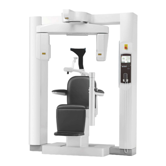
1. Parts Identification Main Unit Head Safety Switch Left-Right Beam Movement Unit Left Support Column Flat Panel Detector Right Support Column X Ray Head Emergency Switch Liquid Crystal Front-Back Beam Display (LCD) Horizontal Beam Control Panel Remote Control Headrest Chinrest Armrest Seat Base Lower, Rear of Left Support Column Control Box Emission Button Emission LED Ready LED... - Page 12 Liquid Crystal Display (LCD) Main Settings Display • Touch the display screen directly to set conditions. (The color of a key will change when it is pressed.) READY Key CTDIvol Display* Emission Time Exposure Keys Not Ready Scan Rotation Keys During Emission Imaging Modes FOV (Field Of View) - Standard Size Keys - High Fidelity - High Resolution...
- Page 13 The display shows the current settings, gives instructions, and may display an error message. Settings Display Example Select either CT or Scout scan. Instructions Example Instruction are displayed. Error Message Example Error message appears in display.
- Page 14 Control Panel BEAM On / Off Key For maintenance only; Turn on/off the beams. not normally used. READY Key Returns arm to start position. Patient IN / OUT Key Move arm to position for patients to get in or out of chair. Arm LOCK / FREE Key Locks the arm in position or frees it. Remote Control Chair Up / Down Keys Move chair up or down. HEAD REST Keys Move headrest up or down. Chair Left / Right Keys Chair Forward / Backward Keys Move chair left or right.
- Page 15 Have the patient move away from the unit, and turn off the Main switch. Restore normal, safe operation in the following way. Rotate the emergency switch in the direction shown by the arrow in the illustration above. Restart the computer. Turn the Main switch back on. Check the unit operates normally and safely. If the unit is not restored to normal, safe operation, contact your local dealer or J. MORITA CORP. Head Safety Switch The Head Safety Switch is activated if the patient’s head touches the arm because the chair is raised too high or the patient stands up.
- Page 16 Patient Positioning Tools and Consumable Parts a. Head Band (A) (2) b. Headrest Cushions (small) (2) c. Head Band (B) (1) d. Headrest Cushions (large) (2) e. Child Seat (1) Support Seat (2) g. Chinrest (1) h. Headrest (1)
-
Page 17: Operation
2. Operation Operation Procedure Float Chart Turn computer on Select and lock patient folder Turn the unit on Check computer Press IN/OUT Key Select FOV Have patient sit in chair Adjust headrest height Stabilize patient’s head Position patient 170 FOV Check patient’s position vis-a-vis head rotation Select 360° or 180° CT Scan Select Scout Select FOV Size Select tube voltage Select Imaging Mode... -
Page 18: Set Up
Set Up * Ambient Operation Conditions: Temperature: +10°C to +30°C. Relative Humidity: 30% to 75% (without condensation). Atmospheric pressure: 70 kPa to 106 kPa. * If an accident occurs, the equipment must not be used until repairs have been completed by a qualified and trained technician provided by the manufacturer. * Have the patient remove glasses, necklaces, earrings and other accessories which could interfere with diagnosis. * If the unit has not been used for some time, make sure it operates normally and safely before actually using it. Turn Computer On Turn the computer on. Startup the i-Dixel software. - Page 19 Turn the Unit On Turn on the Main switch, which is located on the lower back of the left support column. Main switch The Main LED on the control box will light up, and the message, “Checking communication with the Application Software running on the destination PC.” After confirming normal communication with the computer, the unit will display the message, “Press "IN/OUT" key on the control panel.”...
- Page 20 • If the Emergency Switch is accidentally pressed during cleaning or for some other reason, it must be reset by turning it in the direction indicated by the arrow in the illustration before the unit will operate. Check that only the operator is in the vicinity of the equipment and press the IN/OUT key. “CHAIR IS IN MOTION” will appear in the LCD and the seat and arm will move into position to receive the patient.
-
Page 21: Operation Check
Operation Check Before operating this unit, check the following items. • Turn the main switch on and press In / Out key. Check that the arm and the chair automatically move into the patient entry position. • Set the exposure conditions and hold down the emission button. Check that the arm rotates, x rays are emitted and the buzzer sounds. • Release the emission button and check that the x ray emission and arm rotation is terminated immediately and also the buzzer stops. * Move the chinrest arm to the position where it is used by the patient, and adjust it to its lowest position. -
Page 22: [Operation]
[Operation] • In case of electrical storms, immediately let the patient out of the unit and turn off the mains power to avoid an electric shock, fire or system damage caused by power surges. Do not touch the main unit, Control Box, computer, optical receiver or cables. Patient Seating and Positioning •... - Page 23 • Chose as small an imaging area as possible to minimize the absorbed x-ray dosage. • The Flat Panel Detector has two positions: one for 40-140 FOV and another for the 170 FOV. Therefore, it may move when the FOV is selected.
- Page 24 Patient Seating (1) Seat the patient on the chair. Have the patient put on x-ray protection gear and sit down. First adjust Chinrest to its lowest position, and then Open open the Chinrest arm to allow the patient to enter. • Avoid pinching body parts; wait until everything stops moving before have the patient sit in or get out of the chair.
- Page 25 * Use the auxiliary seats if the patient’s head does not Child Seat reach the headrest. Support Seat After the patient sits down, swing the chinrest in front of him/her. Be careful not to hit the patient with it. Forward / The chinrest can be moved up or down and backwards Backward and forwards to line up with the patients chin. Close Up / Down Forwards / Backwards...
- Page 26 * If the armrest is in the way, pull it out slightly and then lower it. • After the patient sits down, do not fail to raise the armrest back up. Proper Seated Position Seated Position Have the patient sit all the way back in the chair with his/her head up against the headrest, hands on both armrests to prevent scrunching up of his/her shoulders, and feet together in the center of the step. Before Moving the Chair Tell the patient you are going to move the chair.
- Page 27 (2) Adjust the height of the Head Rest. Use the headrest keys on the remote control to adjust its height. (The lower edges or the sides of the headrest should generally be about 2 mm above the ears.) Headrest Headrest Keys (3) Gently secure the patient’s head with the Head Band. Fix the head band on with the Velcro tape;...
- Page 28 (4) Adjust the Chin Rest so that it touches the patient’s chin. Adjust the position of the chinrest and have the patient lightly rest his/her chin on it. Chinrest • Never move the headrest after adjusting the head band or chinrest. It may result in injury to the patient.
- Page 29 Patient Positioning • CLASS 2 LASER PRODUCT: A Class 2 laser is used for the positioning beams. Do not stare into the positioning beams. Warn the patient not to look at the positioning beams. Cushions Have the patient rest the back of his/her head straight against the center of the headrest, pull in his/her chin, and straighten his/her back as much as possible. The patient’s Frankfort plane should be parallel to the floor, and the Left-Right beam should be lined up with the patient’s mid-sagittal plane.
- Page 30 Adjust the chinrest so that the patient’s chin rests easily on it. Check that the patient’s head is stabilized by the chinrest. • Do not lean on or put excessive weight on the chinrest. It may be damaged which may result in injury. • Adjust the chinrest carefully without injuring the patient.
- Page 31 Press Next. The chair position will be memorized and the Ready LED on the control box will light up. The main settings display will appear in the control panel. Main Settings Display Press “CT” to make a CT image. Press “Scout” to make a scout image. (See page 40)
- Page 32 For FOV 170×120 Exposures Select FOV 170. * Except for selecting “170”, the part of patient seating procedure is the same as for FOV 40-140. Follow procedures for FOV 40-140 (pages 19 – 24). • In High Resolution and High Speed modes (optional), only 40x40 FOV and 60x60 FOV are available.
- Page 33 Patient Positioning (1) Adjust the chair height to set the Horizontal beam at the region of interest. Use the keys on the remote control so that the lines up with the center of the imaging area. • Never move the headrest after adjusting the head band and chinrest. It may result in injury Horizontal Beam Horizontal Beam to the patient.
- Page 34 Ensure the patient positioning and press “Next” Free the arm and rotate it carefully so that the arm does not hit the patient. Check Patient Positioning (1) Slowly rotate the Rotation Arm manually. (2) Check that the Flat Panel does not contact the patient’s shoulder, the chin-rest or the head-rest during rotation.
- Page 35 • To lock the arm, press the Lock / Free key while the arm is standing still. Press the same key again to free the arm. • To put the unit into Ready mode when the arm is free, press the Ready key while the arm is standing still.
- Page 36 Press Next. The chair position will be memorized and the Ready LED on the control box will light up. The main settings display will appear in the control panel. Main Settings Display Press “CT” to make a CT image. Press “Scout” to make a scout image. (See page 40)
-
Page 37: Ct Exposure Settings
CT Exposure Settings 1. Select CT exposure 2. Select scan rotation (180°/ 360°) 3. I maging Modes * - Standard (Std) - High Fidelity (Hi-Fi) - High Resolution (Hi-Res) - High Speed (Hi-Speed) 7. M emory Key (Exposure conditions memory. Sets initial conditions when unit is turned on.) 4. Select Preset 5. Set Tube Voltage Technique Factor 6. Set Tube Current * Touch the display screen directly to set conditions. - Page 38 1. Press CT. 2. Press 180° or 360°. 3. Imaging Mode. Select the Imaging Mode. - Standard (Std) mode 17 second scan for all applications. - High Fidelity (Hi-Fi) mode - optional 30 second scan for lower noise, better contrast resolution especially at peripheral area of an image, good for zoom reconstruction and volume rendering. - High Resolution (Hi-Res) mode - optional Higher spatial resolution for limited imaging area up to 60×60 FOV by using smaller pixel mode of the flat...
- Page 39 5. Select the Technique Factor. a. Press the Technique Factor. b. Select Lo, Mid, or Hi. c. Hold the Param.Memory key down for 2 seconds. 6. Set tube voltage. (1) Press the Tube Voltage key. (2) U p and Down keys will appear; press them to set the voltage (60 to 90 kV ). (3) Press the Tube Voltage key again.
-
Page 40: No X Ray Setting
To Change the FOV • Follow the message in the display to change from a 40-140 FOV to a 170 FOV or vice versa. • The chair may move when the FOV is changed. i) Change from a 40-140 FOV to a 170 FOV To select the 170 FOV, press the "IN/OUT" key and start over from the FOV Selection. Press “Back” to return to the procedure for a 40-140 FOV exposure. -
Page 41: Ct Exposure
CT Exposure Make sure the Ready LED on the control box is on. Press the Ready key if it isn’t. Insert the key and turn it to the right. Pick up the hand switch and hold down the emission button. X ray emission will begin and be signaled by a melody. Also the control box’s buzzer will sound and the emission LED on the control box will light up. (Also the Ready key in the display will change to its x ray emission status.) Release the emission button when the buzzer stops sounding. -
Page 42: Image Reconstruction
• If the 3D Viewer is running when x ray emission is initiated, it will close automatically, and the i-Dixel application will return to the Image List screen. • If the image in the 3D Viewer has been edited or modified, this data will be saved. •... -
Page 43: Scout Exposure Settings
Scout Exposure Settings [Positioning for Scout Exposure] For 40-140 FOV, check the location of the laser beams. * Making a Scout image simplifies the procedure for making a CT scan. The Scout appears as two images at different angles. Select a point in the two-direction scout to fix the center of the FOV. The arm and slit for the x ray beam will automatically move accordingly. - Page 44 1. Select Scout exposure mode. 2. Select the FOV (field of view) a. Press the FOV key to display the FOV selections (40×40, 60×60, 80×80, 100×100, 140×100,170×120). b. Press the key for the desired FOV. FOV cannot be changed from 170FOV to 40-140FOV or vice versa. Start from IN/OUT FOV size of Scout Exposure is always equal to or larger than that of CT Exposure. FOV size of CT Exposure may be automatically changed depending on the FOV size of Scout Exposure selected.
-
Page 45: Scout Exposure
Scout Exposure Make sure the Ready LED on the control box is on. Press the Ready key if it isn’t. Insert the key and turn it to the right. Pick up the hand switch and hold down the emission button. X ray emission will begin and be signaled by a Emission Button melody. Also the control box’s buzzer will sound and the emission LED on the control box will light up. (Also the Ready key in the display will change to its x ray emission status.) * Hold down the emission button until two exposures are completed (until the melody stops playing). - Page 46 • If the 3D Viewer is running when x ray emission is initiated, it will close automatically, and the i-Dixel application will return to the Image List screen. • If the image in the 3D Viewer has been edited or modified, this data will be saved. •...
- Page 47 If you click Yes, the unit will sound a two-toned beep and a buzzer. The arm and chair will move into their positions, and a new message will appear in the display on the control panel. Click No, if you wish to repeat the scout image or select another type of exposure If you drag a cursor outside the imaging range, it will turn red and a message will appear in the control panel display saying that the setting is out of range.
- Page 48 Change FOV with i-Dixel software Click the CT Area button. A dialogue box will appear. Click the pull down triangle, select the FOV size, and then click OK. • The 170 FOV cannot be selected if the unit is already set for 40-140. A beep will sound and the size of the area will change. • Never take your eyes off the patient during a scout scan.
-
Page 49: Patient Egress
Patient Egress Warn the patient that the chair will move and make sure the area is free of obstacles. Press the In / Out key on the control panel. • The arm and chair will move. In case of an emergency press the emergency switch, any key on the control panel or any key on the remote control except the position memory key. -
Page 50: After Use
After Use Turn the main switch off. Turn off the main switch located on the lower part of the back of the left support column. • Do not fail to turn off the main switch. This eliminates the risk of electrical leakage and accidental operation. - Page 51 Automatic Cooling Intervals of X-Ray Head • To use the x-ray head assembly under appropriate load conditions, leave an interval of approximately 5 minutes for each irradiation and leave an additional 15 minutes after every 3 irradiations. After each irradiation, the system will automatically leave a short interval calculated from the amount of energy based on the current settings of tube voltage, tube current and scan time to cool the x-ray tube down.
-
Page 52: Maintenance, Parts Replacement, And Storage
When cleaning the unit with Ethanol for Disinfection (Ethanol 70 vol% to 80 vol%), take care that none of it seeps inside; this could damage the unit. Parts Replacement * Replace the parts as necessary depending on degree of wear and length of use. For details, see page 45 “Service Life, Consumables, and Replacement Parts”. * Order replacement parts from your local dealer or J. MORITA OFFICE. Storage * Ambient Storage Conditions: Temperature: -5°C to +43°C (+23°F to 109.4°C) Humidity: 8% to 85% (without condensation) Atmospheric Pressure: 70 kPa to 106 kPa No frequent or continuous exposure to direct sunlight. -
Page 53: Regular Inspection
4. Regular Inspection • Maintenance and inspection are generally consider to be the duty and obligation of the user, but if, for some reason, the user is unable to carry out these duties, he/she may rely on a qualified medical device serviceman. Contact your local dealer or J. MORITA CORP. for details. • This unit should be inspected for all the items in the following list once a year. •... - Page 54 Category Test Methods & Standards Instrument etc. There must be no abnormal noise or vibration during any Moving Parts mechanical movement. Greasing * Moving parts must be appropriately greased. Z-axis Belt * There must be no slack or wear. Mechanical No cables must be caught in moving parts or otherwise Movement Routing of Cables * damaged by them.
-
Page 55: Service Life, Consumables, And Replacement Parts
5. Service Life, Consumables, and Replacement Parts Service life refers to the standard period the unit or individual components can be expected to be usable as long as inspection and maintenance procedures specified by J. MORITA MFG. CORP. are followed. Component Service Life List refers to components that can be expected to wear out, degrade or break depending on frequency and conditions of usage, which greatly affects how long these components retain their performance standards. - Page 56 Be sure to turn off the circuit breaker for EX-2 or unplug the power supply cord for EX-1 before servicing to avoid electrical shock. Service The 3D Accuitomo may be repaired and serviced by: • The technicians of J. MORITA’s subsidiaries all over the world. • Technicians employed by authorized J. MORITA dealers and specially trained by J. MORITA. • Independent technicians specially trained and authorized by J. MORITA.
-
Page 57: Troubleshooting
6. Troubleshooting If the equipment operation does not seem to be normal, check or adjust the following before requesting a repair service. • If the equipment does not operate properly after the inspection, adjustment, or parts replacement or if you cannot perform the inspection yourself, contact your local dealer or J. MORITA CORP. • The inside parts of the equipment are charged with high voltage. Do not attempt to perform maintenance or adjustment that is not described in the troubleshooting table. • If an accident occurs, the equipment must not be used until repairs have been completed by a qualified and trained technician provided by the manufacturer. - Page 58 This is displayed when the emergency switch has been actuated. Turn off the power, and after waiting five seconds or more, turn it back on again. If the CT unit still cannot be restored, stop using the unit and contact your local dealer or J. MORITA Corporation directly. This is displayed when the X-ray head is overheated. Leave the CT unit on and wait at least 30 minutes until the unit cools. Leave enough time between exposures for the x ray tube and high voltage circuits to cool off.
- Page 59 This is displayed when a problem has been found in communications with the motor controller of the rotation arm. Press the Ready key on the control panel. If the CT unit cannot be restored, temporarily turn off the power to the CT unit and then restart. If the CT unit still cannot be restored, stop using the unit and contact your local dealer or J. MORITA Corporation directly. This is displayed when abnormal operation of the arm motor has been detected. If continuing operation involves a risk, ask that the patient exit the CT unit, and turn the power briefly off and then on to check for any abnormality in the CT unit.
- Page 60 To avoid danger, automatic positioning in the direction of height and chair-position memory can no longer be used. Since in this case inspection and adjustment are required, please contact your local dealer or J. MORITA Corporation directly. This is displayed when an error has been found in the collimator that limits the X-ray irradiation area.
- Page 61 Problem with chair remote control transmission. Press the Ready key. If this does not solve the problem, turn the unit off and then try again. If this still does not solve the problem, stop using the unit and contact J. MORITA CORP. or your local dealer. Anomaly detected for chair movement. Guide the patient away from the unit. Turn main power off. Wait for 5 seconds. Turn power back on again. If this still does not solve the problem, stop using the unit and contact J. MORITA CORP. or your local dealer. Anomaly detected for chair movement.
- Page 62 Anomaly detected for chair movement. Guide the patient away from the unit. Turn main power off. Wait for 5 seconds. Turn power back on again. If this still does not solve the problem, stop using the unit and contact J. MORITA CORP. or your local dealer. Anomaly detected for chair movement. Guide the patient away from the unit. Turn main power off. Wait for 5 seconds. Turn power back on again. If this still does not solve the problem, stop using the unit and contact J. MORITA CORP. or your local dealer. Anomaly detected for chair movement.
- Page 63 Make sure the unit is operating normally and safely. If normal operation has been restored, check that the unit is safe for the patient and press the Ready key. Scout scan was not completed. The second exposure was cancelled by releasing Emission Button after the first exposure. Emission Button must be kept pressed until the second exposure is completed. Press READY key and retry scout scan. Scout scan was interrupted during the second exposure. Emission Button may have been released before the second exposure is completed. Press READY key and retry scout scan. If this error still occurs even though Emission Button is kept pressed, stop using the unit and contact J. MORITA CORP. or your local dealer.
- Page 64 There is some problem with the back-up or teaching data. This requires inspection and adjustment. Contact J. MORITA CORP. or your local dealer. CT position selected by Scout scan is cancelled when the chair position is moved manually by Remote Control. Press READY key and start from selecting the CT imaging area on the PC again, or taking another scout scan. CT scan can be taken at the position manually selected by Remote Control. However, the link from the scout image to the CT image will be cancelled and the CT image can not be opened from the scout image.There is some problem with the back-up or teaching data. This requires inspection and adjustment. Contact J. MORITA CORP. or your local dealer.
-
Page 65: Cautionary Remarks On Imaging
7. Cautionary Remarks on Imaging Artifacts Due to Sensitivity Discrepancies of the Flat Panel Detector The flat-panel detector (FPD) is an extremely dense and precise array of photo diodes (pixels). By compensating for the discrepancy in pixel sensitivity, the image can show greater detail than ordinary fluoroscopy. However, this discrepancy cannot be completely eliminated when a CT image is reconstructed. - Page 66 Fig. 2 Example of an Artifact...
- Page 67 Artifacts due to Metal Prosthetics Useful images may not be possible if a patient has metal fillings or prosthetic devices, and it is usually impossible to make a useful image of a crown if it is right next to a metal prosthetic. Also it is sometimes impossible to make useful images of a root or jaw bone if there is a metal post, crown or other prosthetic right next to it.
- Page 68 Image Area Photos 4 No metal Prosthetic (Top: Model and Image Area. Bottom: Images.)
- Page 69 Image Area Metal Prosthetic Photos 5 Full metal crown is on the opposite side of the image area. (Top: Model and Image Area. Bottom: Images.)
- Page 70 Image Area Metal Prosthetic Photos 6 Imaging area on same side as metal crown (Top: Model and Image Area. Bottom: Images.)
- Page 71 Photos 7 Post and Crown Left: P ost and Crown made after filling root canal with gutta percha and point. Center: Post and Crown attached to tooth. Right: S imple dental x ray.
- Page 72 Image Area Post and Crown Photos 8 Image area on opposite side. (Top: Model and Image Area. Bottom: Images.)
- Page 73 Image Area Post and Crown Photos 9 Image area on same side (Top: Model and Image Area. Bottom: Images.)
- Page 74 Artifacts for 180° Exposures For 180º exposures, when the X-ray beam passes through the lower plane (a) in Figure 10, the result is the flat shape shown in Figure 11, where the beginning of 180º circuit matches the end of the circuit. However, when the X-ray beam passes through the upper plane (b) in Figure 10, the result is the conical shape shown in Figure 12, where there is a discontinuity between the beginning and end of the circuit.
-
Page 75: Technical Specifications
8. Technical Specifications Specifications Model MCT-1 Type EX-2 F17 Classification Protection against electric shock CLASS I, TYPE B Protection against ingress of liquids IPX 0 Type B applied parts H eadrest, Chinrest, seat, and headband (no conductive connection to patient) Disinfection methods: - B etween patients, type B applied parts disinfect by wiping them with Ethanol for Disinfection (Ethanol 70 vol% to 80 vol %). Disposable paper sheets can be used for this purpose, also. - Occasionally, control panel, remote controller, headrest, chinrest, seat and headband should be wiped with Ethanol for Disinfection (Ethanol 70 vol% to 80 vol %), and LCD surface should be wiped with dry cloth. - Page 76 Generator/X-Ray Head Assembly Tube D-051 Focal Spot Target Angle 5º Target Material Tungsten Scan Modes Standard (Std) mode High Fidelity (Hi-Fi) mode (optional) High Resolution (Hi-Res) mode (optional) High Speed (Hi-Speed) mode (optional) Operating Tube Potential 60 kV to 90 kV(accuracy of displayed values ±10%) Operating Tube Current 1 mA to 10 mA (accuracy of displayed values ±10%) limited up to 8 mA in Hi-Fi and Hi-Res modes Reproducibility of Air Kerma Coefficient of variation max. 0.05 Maximum Output Power 0.9 kW nominal at 90 kV, 10 mA FOV 40 × 40 to 170 × 120 mm (Diameter × Height) limited up to 60 × 60 mm in Hi-Res and Hi-Speed modes...
- Page 77 Mechanical Parameters SID 740 (±20) mm for FOV 170 diameter 840 (±20) mm for FOV other diameters SOD (source-object) 540 (±20) mm 200 (±20) mm minimum Outer Dimensions Main Unit W 1,620 mm × D 1,200 mm × H 2,080 mm Control Box W 70 (96) mm × D 40 mm × H 115 mm Vertical Height of Focal Spot 1,480 (±20) mm Weight of C-arm approx. 70 kg Patient Positioning Positioned using 3 positioning beams and an electrically operated positioning system (Scout) Exposure Time Standard mode...
- Page 78 The package should be recycled. Metal parts of the equipment are disposed as scrap metal. Synthetic materials, electrical components, and printed circuit boards are disposed as electrical scrap. Material must be disposed according to the relevant national legal regulations. Consult specialized disposal companies for details. Please consult local city/community administrations concerning local disposal companies. This symbol indicates that the waste of electrical and electronic equipment must not be disposed as unsorted municipal waste and must be collected separately. Contact your local dealer or J. MORITA OFFICE for details. Collimator MCT-1F17 Collimator - motorized variable collimator.
- Page 79 2. The following equipment connected to the analog and digital interfaces must be certified according to the respective IEC standards (i.e. IEC 60950-1 for data processing equipment and IEC 60601-1 for medical equipment). Everybody who connects additional equipment to the signal input part or signal output part configures a medical system, and is therefore responsible that the system complies with the requirements of IEC 60601-1. If in doubt, consult the nearest J. MORITA OFFICE, its representative or its dealer for help. Some of the following devices may cause some technical problems with 3D Accuitomo. Ask your nearest J. MORITA OFFICE for proper selection of equipment and connections. Hardware Windows based Personal Computer CPU: Pentium 4 3GHz or higher, or compatible.
- Page 80 * Computers or any other external devices must be connected in accordance with IEC 60601-1. * Computers or any other external devices must be cleaned in accordance with the manufacturer’s instructions. * Computers or any other external devices must be transport, storage, and operation in accordance with the manufacturer’s instructions. Application Software Application software i-Dixel ver. 2.3 or later provided by J. MORITA is used to process and view the images. It shall be used with an Windows based computer matching to the above mentioned specifications.
-
Page 81: Symbols And Markings
Symbols and Markings * Some symbols may not be used. Caution Label Laser Caution Label Laser Radiation Focal Spot Emergency Stop Type B Applied Part Laser Radiation X-ray Tube Head Assembly Label Warning Label Rating Label Main Switch : On : Off Notice Label Equipotentiality Use this terminal when it is required to use potential equipotentialization Warning Label conductors, do not use for protective earth connection. - Page 82 Package * Some symbols may not be used. This way up Fragile Keep away from rain Temperature limitation Humidity limitation Atmospheric pressure limitation Attention, consult accompany documents Do not reuse Country or region Prescription Device (Country Names: Conforming to the CAUTION: Federal law restricts this device ISO 3166-1 alpha-3 codes and EU for to sale by or on the order of a dentist and a European Union) licensed healthcare practitioner.
- Page 83 Indicated Items on the Rating Label and X-ray Tube Head Assembly Label * For details, refer to “Technical Specifications” (p.65). * Some symbols described on the previous page may be included. Rating Label Model: Model of X-ray system Type: Type Input: Rated input voltage, frequency, and power in operation Standby: Input power in standby Duty Cycle: Duty cycle of X-ray system...
- Page 84 Tube Housing Assembly Information Heating Curve (kJ) (min) Cooling Curve (kJ) (min)
- Page 85 Tube Rating Chart Maximum Rating Chart (Absolute Maximum Rating Charts) D051 Focal Spot: 0.5mm 70kV 80kV 60kV 50kV 90kV 100kV EXPOSURE TIME (S) Anode Thermal Characteristics D051 230W 280W 170W COOLING HEATING TIME (min)
- Page 86 Relationship of Focal Spot, X-ray Beam and Image Detector...
-
Page 87: Electromagnetic Disturbances (Emd)
9. Electromagnetic Disturbances (EMD) The 3D Accuitomo XYZ Slice View Tomograph (Model: MCT-1, hereafter "this device") conforms to IEC 60601-1-2 Edition 4.1, the relevant international standard for electromagnetic disturbances (EMD). Use Environment The use environment of this device is the Professional healthcare facility environment. • Use of this device adjacent to or stacked with other equipment should be avoided because it could result in improper operation. If such use is necessary, this device and the other equipment should be observed to verify that they are operating normally. - Page 88 Electromagnetic Immunity Test IEC 60601 Test Level Compliance Level Environment – Guidance Electrostatic ±8 kV contact ±2 kV, ±4 kV, ±6 kV, ±8 kV Floors should be wood, discharge (ESD) ±2 kV, ±4 kV, ±8 kV, contact concrete or ceramic tile. IEC 61000-4-2 ±15 kV air ±2 kV, ±4 kV, ±8 kV,...
- Page 89 IEC 60601 Electromagnetic Environment Immunity Test Compliance Level Test Level – Guidance Conducted RF Portable and mobile RF IEC 61000-4-6 / amateur radio / amateur radio communications equipment should frequency band: 6 V frequency band: 6 V be used no closer to any part of this 150 kHz to 80 MHz 150 kHz to 80 MHz device, including cables, than the recommended separation distance...
- Page 90 Pass / Fail Criteria on Immunity Test • No X-ray irradiation without active operation of the emission button. • X-ray termination with release of the emission button. • No unexpected movement of the equipment. NOTE: If the essential performance is lost or degraded due to electromagnetic disturbance, unexpected movement would be initiated without any active of operation, or X-ray termination would not be done by releasing the Emission switch, or X-ray would be irradiated without an active operation of the Emission switch.
Need help?
Do you have a question about the 3D Accuitomo and is the answer not in the manual?
Questions and answers