Table of Contents
Advertisement
Advertisement
Table of Contents

Subscribe to Our Youtube Channel
Related Manuals for Morita Root ZX mini


Summary of Contents for Morita Root ZX mini
- Page 1 Apex Locator Root ZX mini Operation Instructions Thinking ahead. Focused on life.
-
Page 2: Table Of Contents
Checking the Function 2. Operating the Unit Operation Panel Display and Switches Settings Meter Display Root Canal Not Suitable for Electronic Measurement Root ZX mini Meter Reading and Radiography 3. After Using the Unit 4. Replacing Batteries Maintenance Cleaning Disinfection... - Page 3 Symbols Electromagnetic Disturbances (EMD) Thank you for purchasing the Root ZX mini. For optimum safety and performance, read this manual thoroughly before using the unit and pay close attention to warnings and notes. Keep this manual in a readily accessible place for quick and easy reference.
-
Page 4: Prevent Accidents
After instructing the customer in the operation of the equipment, have him fill out and sign the war- ranty. Then fill in your own section of the warranty and give the customer his copy. Do not fail to send the manufacturer’s copy to J. MORITA MFG. CORP . Prevent Accidents Most operation and maintenance problems result from insufficient attention being paid to basic safety precautions and not being able to foresee the possibilities of accidents. - Page 5 7 . Fires, earthquakes, floods, lightning, natural disasters, or acts of God. ■ The useful life of the Root ZX mini is 6 years (based on self-certification) from the date of ship- ment provided it is regularly and properly inspected and maintained.
-
Page 6: Warnings And Prohibitions
EMC performance of the Root ZX mini. • As far as possible, do not use the Root ZX mini near or simultaneously with other devices. If this cannot be avoided, observe carefully and make sure both the Root ZX mini and the other device operate normally. -
Page 7: Parts Identification And Accessories
Parts Identification and Accessories Parts Identification File Holder Contrary Electrode Strap Holes LCD Screen Set Switch Power Switch Data Output Port (to transmit display data) Probe Cord Accessories ⹅ Standard Accessories Probe Cord File Holder Contrary Electrode Tester Alkaline Dry Cells (LR03 (AAA size) batteries) ⹅... -
Page 8: Usage
3. Slide the cover all the way down until it is securely closed. • The Root ZX mini is shipped without the batteries installed. Remove the cover and install the 3 LR03 (AAA size) batteries. • Do not reverse the plus and minus poles. -
Page 9: Connecting The Probe Cord
Check that all the meter indicator bars on the display light up. • Handle the Root ZX mini carefully; do not drop, bump or expose the unit to other kinds of impacts or shocks. Rough handling could cause damage. - Page 10 • Check the Root ZX mini operation before each patient. If the indicators in the display do not all appear normally, the instrument may not be able to make an accurate measurement. In this case, stop using the instrument and have it repaired.
-
Page 11: Operating The Unit
Position of Flash Bar • Never connect the Root ZX mini to any device not approved by J. MORITA MFG. CORP . • Never use the unit if the battery power indicator is flashing on and off. The unit may not function properly if the battery power is low. -
Page 12: Settings
Settings 1. Select Memorized Flash Bar Method Press Set Switch. Each press of the Set Switch will change the memory selected in the sequence 01 to 02 to 03 and then back to 01 again. The Flash Bar set for each memory will appear when that memory is selected. - Page 13 • The Memory Bar can be set at a different point for each of the 3 memories. • The Memory Bar will stay wherever you set it until the Root ZX mini is turned off, but it will not be memo- rized.
-
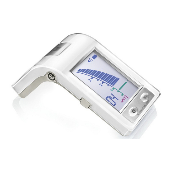
Page 14: Meter Display
Meter Display The position of the fi le tip is shown by the canal length indicator bar on the display. The Flash Bar fl ashes on and off once fi le is inserted into the root canal. Flashes The meter’s 0.5 reading indicates that the tip of the fi le is in or very near the apical constriction. - Page 15 Operating the Unit 1. Turn the unit on. 2. Hook the contrary electrode in the corner of the pa- tient’s mouth. Contrary Electrode 3. Clip the file holder to the metal shaft of the file. (1) Press in direction of arrow with the thumb. (2) Clip file.
- Page 16 Operating the Unit GOOD 4. Press the Set Switch to select Memory 01, 02 or 03. Set Switch 5. Insert the fi le up to the Flash Bar (this point can also be recognized by the change in the beeping). Position the rubber stopper on the tooth surface as a reference point to determine the root canal’s working length.
-
Page 17: Root Canal Not Suitable For Electronic Measurement
Root Canal Not Suitable for Electronic Measurement Accurate measurement cannot be obtained with the root canal conditions shown below. There may be cases other than these where an accurate measurement cannot be made. Root Canal with a large apical foramen Root canal that has an exceptionally large apical foramen due to a lesion or incomplete development cannot be ac- curately measured;... - Page 18 Root Canal Not Suitable for Electronic Measurement Crown or metal prosthesis touching gingival tissue Crown Accurate measurement cannot be obtained if the file touches a metal prosthesis that is touching gingival tissue. In this case, widen the opening at the top of the crown so that the file will not touch the metal prosthesis before tak- ing a measurement.
-
Page 19: Root Zx Mini Meter Reading And Radiography
Sometimes the Root ZX mini meter reading and the X-ray image will not correspond. This does not mean that the Root ZX mini is not working properly or that the X-ray exposure is a failure. * Occasionally, the actual apical foramen does not correspond exactly. The actual apical foramen may be located up towards the crown. -
Page 20: After Using The Unit
3. After Using the Unit 1. Turn the unit off. * The unit will automatically turn off after 10 minutes of non-use. 2. Disconnect the probe cord and other cords or cables. Cord Always grip the connectors to connect and disconnect cords. •... -
Page 21: Replacing Batteries
1. Slide the cover in the direction by the arrow in the illus- tration and remove it from the Root ZX mini. 2. Insert the 3 LR03 (AAA size) batteries included in the package. - Page 22 3. Slide the cover all the way down until it is securely closed. * Overheating or malfunctions could result if the above conditions are not adhered to. * The three LR03 alkaline dry cells used for this equipment will last for about 70 hours of use. (This equals 6 to 12 months at the normal rate of usage.) •...
-
Page 23: Maintenance
Maintenance Be sure to follow the procedure below when performing daily maintenance. Cleaning Disinfection Packing Sterilization • Components maintained this way: File Holder Contrary Electrode Long File Holder (option) Take out the fi le before cleaning the fi le holder. Other than the components listed above, refer to page 23 “Disinfection”... -
Page 24: Disinfection
Any other cleaning chemical or products should not be used including but not limited to the following cleaning products and similar cleaning products listed below because of the poten- tial damage to the plastic components of the Root ZX mini. • CaviWipes™... -
Page 25: Packing
Packing Individually place the fi le holder or long fi le holder, and contrary electrode in a sterilization pouch. Do not put stress on the cable when you place the fi le holder in a sterilization pouch. Sterilization Autoclave the fi le holder, contrary electrode, and long fi le holder after use for each patient. -
Page 26: Replacement Parts, Transport And Storage
Replacement Parts * Replace the parts as necessary depending on degree of wear and length of use. * Order replacement parts from your local dealer or J. MORITA OFFICE. Transport and Storage Environments Temperature: -10 °C to +45°C (+14°F to +113°F) -
Page 27: Inspection And Warranty
Inspection and Warranty • Maintenance and inspection are generally consider to be the duty and obligation of the user, but if, for some reason, the user is unable to carry out these duties, contact J. MORITA MFG. CORP . for details. -
Page 28: Warranty
The Root ZX mini may be repaired and serviced by: • The technicians of J. MORITA’s subsidiaries all over the world. • Technicians employed by authorized J. MORITA dealers and specially trained by J. MORITA. • Independent technicians specially trained and authorized by J. MORITA. -
Page 29: Troubleshooting
* If the user is unable to inspect the equipment himself or if the equipment fails to work properly after being adjusted or after parts are replaced, contact your local dealer or J. MORITA OFFICE. Problem Check Points... - Page 30 Problem Check Points Response Canal Length Indica- Are there lateral canals or is the The canal length indicator bar may jump to “APEX” tor overreacts or is tooth fractured? when it reaches the opening of a lateral canal or too sensitive. the opening of a fractured tooth that allows the (Measurements current to flow to the gingival tissue.
-
Page 31: Technical Specifications
Protection against Electric Internal powered ME equipment / Type BF applied part Shock Intended Use The Root ZX mini is intended to detect the apex of the root canal. Operating Principle The impedance in the root canal is measured by measur- ing at two frequencies and the position of the treatment instruments in the root canal is detected. -
Page 32: Symbols
Symbols * Some symbols may not be used. CE(0197) marking Serial number Conforms with the European Directive, 93/42/EEC. CE marking Conforms with the European Directive, 2011/65/EU. Type BF applied part GS1 DataMatrix Manufacturer Date of manufacture Marking of electrical equipment Autoclavable up to in accordance with the Europe- +135°C (+275°F) -
Page 33: Electromagnetic Disturbances (Emd)
EMD information provided in the ACCOMPANYING DOCUMENTS. • Use of parts other than those accompanied or specified by J. MORITA MFG. CORP . could result in increased electromagnetic emissions or decreased electromagnetic immunity of this device and result in improper operation. - Page 34 Guidance and Manufacturer’s Declaration – Electromagnetic Immunity This device is intended for use in the electromagnetic environment specified below. The customer or the user of this device should assure that it is used in such an environment. Electromagnetic Immunity Test IEC 60601 Test Level Compliance Level Environment –...
- Page 35 Guidance and Manufacturer’s Declaration – Electromagnetic Immunity This device is intended for use in the electromagnetic environment specifi ed below. The customer or the user of this device should assure that it is used in such an environment. Immunity Test IEC 60601 Test Level Compliance Level Electromagnetic Environment –...
- Page 36 The authority granted to the authorized representative, MEDICAL TECHNOLOGY PROMEDT Consulting GmbH, by J. MORITA MFG. CORP . is solely limited to the work of the authorized representative with the requirements of the European Directive 93/42/EEC for product registration and incident report.
Need help?
Do you have a question about the Root ZX mini and is the answer not in the manual?
Questions and answers