
Subscribe to Our Youtube Channel
Related Manuals for Morita Veraview X800


Summary of Contents for Morita Veraview X800
- Page 1 INSTRUCTIONS FOR USE Cephalo This manual is for making cephalo exposures. Use it along with the manual for panorama and CT exposures.
-
Page 2: Table Of Contents
Table of Contents 1 Prevent Accidents ....................3 2 Parts Identification ....................4 3 Before and After Use .................... 6 3.1 Operation Conditions......................6 3.2 Set Up ............................. 6 3.3 Start-up Inspection ....................... 10 3.4 After Use ..........................11 4 Cephalo Exposure ....................12 4.1 Exposure Types and Functions .................... -
Page 3: Prevent Accidents
Prevent Accidents Attention Customers This manual is for making cephalo exposures with the Veraview X800. It must be used along with the Veraview X800 manual for panorama and CT exposures. Keep this manual in a readily accessible place for quick and easy reference. -
Page 4: Parts Identification
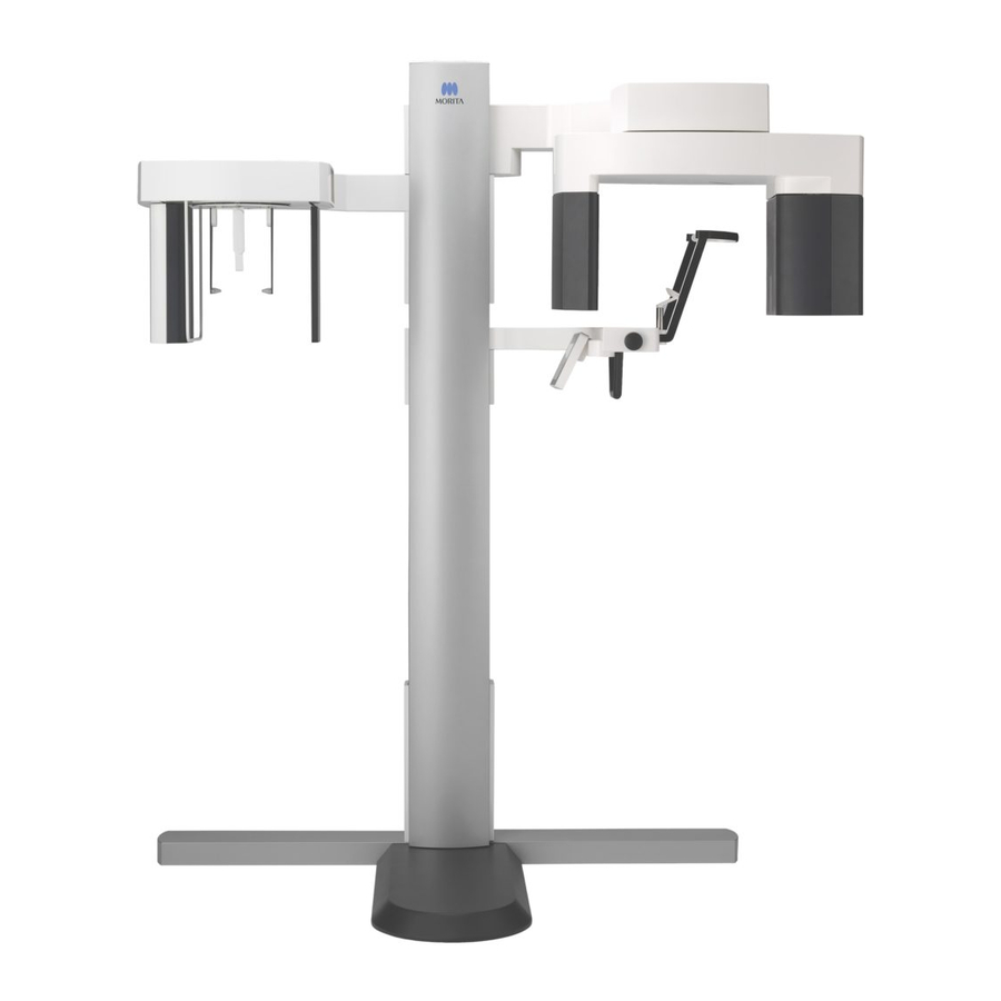
Parts Identification ⹅ Main Unit Lift (upper) Arm Support Cephalo Support Chinrest Temporal Stabilizer Temporal Stabilizer Knob Cephalo Unit Patient Handle Control Panel Lift (lower) Emergency Stop Switch Control Panel Support Column ⹅ Control Box Emission Switch Power Switch Emission LED Ready LED Power LED Base... - Page 5 ⹅ Cephalo Unit Cephalo Control Panel Head Positioner Nasion Plate Cephalo Slit Patient Guard X-ray Detector Ear Rods Ear Rod Plate ⹅ Control Panel Blue icons and the Ready key are activated by touch. ● Main Unit ● Cephalo Unit Beam On/Off Switch In/Out Switch Up and Down Switches...
-
Page 6: Before And After Use
Before and After Use Operation Conditions ● Use the Veraview X800 under the following conditions: Temperature: +10°C to +35°C (+50°F to +95°F) Humidity: 30% to 75% (without condensation); Atmospheric Pressure: 70 kPa to 106 kPa * If an accident occurs, the equipment must not be used until repairs have been completed by a qualified and trained technician authorized by the manufacturer. - Page 7 3.2 Set Up 3. Open X800 Exposure window Click the X800 Exposure Window icon (C). When the window opens, an exposure can be made. • When a patient is selected with i-Dixel WEB, the patient name appears on the title bar for the X800 Exposure Window. Before making the exposure, make sure the name on the title bar is the name of the patient subject to the exposure.
- Page 8 5. Turn on the Power switch. 6. Check the panorama, CT, and cephalo exposure operation. If the unit cannot be returned to a safe condition or will not operate, contact your local dealer or J. MORITA OFFICE. Instructions for Use 2017-04-10...
- Page 9 Release the Emergency Stop switch, and then turn on the unit. When starting up the Veraview X800 right after turning it off (e.g., rebooting the equipment), wait at least 5 seconds to turn it on again. Failure to do so could result in malfunction or damage to the equipment.
-
Page 10: Start-Up Inspection
3 Before and After Use Start-up Inspection Before use make a start-up inspection to make sure the unit will operate properly and safely. 1. Open the image list for the start-up inspection Select the test patient used for the start-up inspection from the i-Dixel WEB patient list and display the image list for it. -
Page 11: After Use
• Do not fail to turn off the Power switch. This prevents the risk of current leakage, inad- vertent operation, etc. When starting up the Veraview X800 right after turning it off (e.g., rebooting the equip- ment), wait at least 5 seconds to turn it on again. Failure to do so could result in mal- function or damage to the equipment. -
Page 12: Cephalo Exposure
Cephalo Exposure Exposure Types and Functions 4.1.1 Exposure Area (ROI: Region Of Interest) ⹅ Lateral Lateral cephalometric exposure. Lateral Exposure ⹅ PA (Posterior-Anterior) PA cephalometric exposure. PA Exposure ⹅ 45° Angle ⹅ Hand Cephalometric exposure at 45° angle. Cephalometric hand exposure. Instructions for Use 2017-04-26... -
Page 13: Partial Cephalo
4.1 Exposure Types and Functions 4.1.2 Partial Cephalo A partial cephalometric exposure trims the X-ray field and reduces the patient’s X-ray dosage. There are three ways to trim a lateral exposure, and one way to trim a PA exposure. ● Lateral Exposure ●... -
Page 14: Operation And General Settings
4 Cephalo Exposure Operation and General Settings 4.2.1 Cephalo Display 1. Cephalo Mode Key Numbers 2 to 8 show the Ceph current settings. Touch any one of the icons to show 00.00 0000.0 mGy . cm other selections. Ceph Size Size Dens Dens... -
Page 15: Settings
4.2 Operation and General Settings 4.2.2 Settings Density Dens. Comp. Exposure Area Patient Size Exposure Setting Tube Voltage Tube Current Compensation Start Pos. (ROI) (Size) (Exp) (kV) (mA) (Dens Comp) (Soft Tissue) Lateral (Manual Exposure) 45° Angle (No X-ray Emission) Hand ⹅... -
Page 16: Lateral, Pa, And 45° Angle Exposures
4 Cephalo Exposure Lateral, PA, and 45° Angle Exposures 4.3.1 Preparation Ceph 1. Select the cephalometric exposure mode. 00.00 0000.0 mGy . cm Touch the Ceph key to select the cephalometric exposure mode. Size Dens Comp Soft Tissue Ready 2. Select the exposure area Ceph Touch the icon to the right of “ROI”... - Page 17 4.3 Lateral, PA, and 45° Angle Exposures Ceph 4. Set density compensation * Lateral and PA only. Touch the icon to the right of “Dens Comp” to turn it on and off. Size Dens Comp Soft What is Density Compensation (Dens Comp)? Tissue This is used for an image that will show both soft and hard tissues.
- Page 18 4 Cephalo Exposure Ceph Ceph 6. Make exposure setting 00.00 0000.0 mGy . cm Size Touch the letter under “Exp” to make the exposure setting. Size * The auto feature cannot be used for cephalo exposures. Dens Dens Comp Comp Manual Exposure Soft Soft...
- Page 19 4.3 Lateral, PA, and 45° Angle Exposures Ceph 9. Select areas to cut 00.00 0000.0 mGy . cm * Lateral and PA only, as necessary. Size To reduce the patient’s X-ray dosage, no X-rays will be emitted to Dens Comp selected areas.
- Page 20 4 Cephalo Exposure 12. Set cephalo head positioner Set the head positioner at the correct angle for the intended exposure. Lateral Position PA Position 45° Angle Position If for a PA exposure, the nasion plate is slid to the outside, something could be damaged.
- Page 21 4.3 Lateral, PA, and 45° Angle Exposures 13. Put ear rods on Put the ear rods on their shafts. • Disinfect the ear rods and the nasion plate after each use by wiping it with etha- nol (70 vol% to 80 vol%). Replace it if it is worn, damaged, or dirty. Instructions for Use 2019-03-22...
-
Page 22: Patient Entry And Positioning
4 Cephalo Exposure 4.3.2 Patient Entry and Positioning 1. Prepare patient Have the patient wear an X-ray protection apron etc. • Patient must remove glasses and all accessories like necklaces etc. Otherwise the exposure could fail. • Make sure the patient’s hair cannot get caught in moving parts. 2. - Page 23 4.3 Lateral, PA, and 45° Angle Exposures 3. Insert ear rods Use the Up and Down switches to raise or lower the unit so that the ear rods are line up with the patient’s outer ear orifice. • When lowering the cephalo unit and cephalo support, take care that it does not hit the patient.
- Page 24 4 Cephalo Exposure 4. Patient positioning * Lateral only Press the Beam On/Off switch. The X-ray detector will move and the horizontal beam will light Move the patient’s head to line it up with the beam. Check that the beam is lined up with the patient’s orbitale (A) and that the patient’s mid-sagittal plane is perpendicular.
-
Page 25: Exposure
4.3 Lateral, PA, and 45° Angle Exposures 4.3.3 Exposure Ceph 1. Check ready state 0000.0 mGy . cm Check that the Ready key on the control panel and the Ready Size LED (green) on the control box are on. Dens Comp Soft Tissue... -
Page 26: Patient Egress
4 Cephalo Exposure 4.3.4 Patient Egress 1. Guide patient away from the unit ● Lateral Exposure Pull the nasion plate out and then swing it up. ● PA and 45° Angle Exposures Press the In/Out switch to move the cephalo slit to the right edge. -
Page 27: Image Transmission
4.3 Lateral, PA, and 45° Angle Exposures 4.3.5 Image Transmission 1. Image transmission After the exposure is completed, the image is sent to i-Dixel WEB. During transmission, the Ready LED is red and blinks on and off. Ceph 2. Image reconstruction 0000.0 mGy . - Page 28 4 Cephalo Exposure * Automatic density compensation is used for digital exposures to make a better image. However, if some areas of the image are exceptionally dark, the density compensation will tend to make the entire image whiter than usual. * Horizontal lines divide the image into three parts.
-
Page 29: Hand Exposure
4.4 Hand Exposure Hand Exposure 4.4.1 Preparation Ceph 1. Select cephalometric exposure mode 00.00 0000.0 mGy . cm Touch the Ceph key to select the cephalometric exposure mode. Size Ready 2. Select exposure type Touch the icon to the right of “ROI” to select the hand. Ceph Size Hand Icon... - Page 30 4 Cephalo Exposure Ceph 5. Set tube voltage Ceph 00.00 0000.0 mGy . cm Touch the number under “kV” to set the voltage. Size It can be set from 60 – 100 kV in 5 kV increments. Estimated voltage: 65 kV (all patient sizes) Size Current Setting Ready...
- Page 31 4.4 Hand Exposure Ceph 8. Touch Ready key 00.00 0000.0 mGy . cm Touch the Ready key. Size The X-ray head will turn to its cephalo direction and the arm will automatically go to its cephalo exposure position. • Make sure the patient is not near the unit when you touch the Ready key. Other- Ready wise the arm might hit the patient.
-
Page 32: Patient Entry And Positioning
4 Cephalo Exposure 4.4.2 Patient Entry and Positioning 1. Patient entry Have the patient place his hand inside the rectangle on the hand plate. • Make sure nothing other than the patient’s hand is inside the rectangle on the hand plate. 2. -
Page 33: Exposure
4.4 Hand Exposure 4.4.3 Exposure Ceph 1. Check ready state 0000.0 mGy . cm Check that the Ready key on the control panel and the Ready Size LED (green) on the control box are on. Ready 2. X-ray emission Hold down the Emission switch. Emission will start after a few seconds and the cephalo slit will move. -
Page 34: Patient Egress
4 Cephalo Exposure 4.4.4 Patient Egress 1. Guide patient away from the unit 2. Remove hand plate • Do not fail to remove the hand plate after the exposure is completed. If a cephalo exposure is made with the hand plate in place, the resulting image will not be good enough for diagnosis. -
Page 35: Cephalo Image Enhancement
4.5 Cephalo Image Enhancement Cephalo Image Enhancement If it is hard to identify measurement points in Cephalo images, the Auto Image Enhancement (AIE) soft- ware feature of the i-Dixel WEB can be used to identify them more precisely. 4.5.1 AIE (Auto Image Enhancement) The AIE software feature equalizes the density for panorama and cephalo images and makes them sharper and clearer. - Page 36 4 Cephalo Exposure ● AIE Default Settings You can make AIE default settings so that the AIE feature is applied to every image automatically. To make default settings, go to the Maintenance page and then click the Imaging tab. [NOTE] It may take longer to process images when the AIE function is used, especially in the following cases: •...
-
Page 37: Examples Of Aie Images
4.5 Cephalo Image Enhancement 4.5.2 Examples of AIE Images These examples show the difference between turning the AIE Boost on and off. ⹅ Make Measurement Points Clearer A. Check the Apply box B. Select the AIE C. Set the AIE Correction Level D. - Page 38 4 Cephalo Exposure ⹅ Make Measurement Points Even Clearer A. Check the Apply box B. select the AIE C. set the AIE Correction Level D. and turn the AIE Boost on Without AIE With Low AIE Correction Level and AIE Boost turned on ●...
-
Page 39: Notes For Exporting Cephalo Data To Analysis Software
4.6 Notes for Exporting Cephalo Data to Analysis Software Notes for Exporting Cephalo Data to Analysis Software Whenever cephalo data is exported to analysis software, calibration must be performed to create compat- ibility between the cephalo image and the analytic software. •... -
Page 40: Maintenance, Parts Replacement, And Storage
Maintenance, Parts Replacement, and Storage Maintenance Always turn off the Power switch before performing regular maintenance. Wipe with ethanol (70 vol% to 80 vol%) once a day • Control Panel Wipe with ethanol (70 vol% to 80 vol%) after each patient •... -
Page 41: Replacement Parts
* Replace the parts as necessary depending on degree of wear and length of use. Refer to the manual of Panorama and CT, “12 Service Life, Consumables, and Replacement Parts”(p.112). * Order parts from local dealer or J. MORITA OFFICE. Storage Store the Veraview X800 under the following conditions: Temperature: -10°C to +50°C (+14°F to +122°F);... -
Page 42: Troubleshooting
* If the user is unable to inspect the instrument himself or if the instrument fails to work properly after being adjusted or after parts are replaced, contact your local dealer or J. MORITA OFFICE. * The inside parts of the equipment are charged with high voltage. Do not attempt to perform mainte- nance or adjustment that is not described in the troubleshooting table. - Page 44 Pub. No.: X3256-EN-10 Printed in Japan...
Need help?
Do you have a question about the Veraview X800 and is the answer not in the manual?
Questions and answers