Advertisement
PK-4PZ
Electromagnetic
Do not dispose of this device in the trash along with other waste!
According to the Law on Waste, electro coming from households free of charge and can
give any amount to up to that end point of collec� on, as well as to store the occasion of
the purchase of new equipment (in accordance with the principle of old-for-new, regard-
less of brand). Electro thrown in the trash or abandoned in nature, pose a threat to the
environment and human health.
Purpose
Electromagnetic relay in a single-module housing for direct mo-
unting on the TH-35 rail.
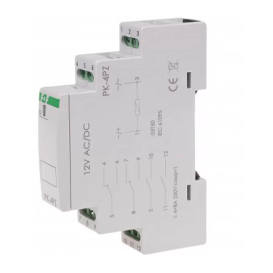
Functioning
When the supply voltage is applied to the relay coil, the contacts
are switched into positions 5-6, 8-9, 2-10 and 11-12.
This state is indicated by a green LED.
After a power failure, the contacts return to the positions: 5-4, 8-7,
and contacts 2-10 and 11-12 are opened up.
F&F Filipowski sp. j.
Konstantynowska 79/81, 95-200 Pabianice, POLAND
phone/fax (+48 42) 215 23 83 / (+48 42) 227 09 71
www.fif.com.pl; e-mail: biuro@fif.com.pl
110 V
relay
- 1 -
Advertisement
Table of Contents

Subscribe to Our Youtube Channel
Related Manuals for F&F PK-4PZ


Summary of Contents for F&F PK-4PZ
- Page 1 F&F Filipowski sp. j. Konstantynowska 79/81, 95-200 Pabianice, POLAND phone/fax (+48 42) 215 23 83 / (+48 42) 227 09 71 www.fif.com.pl; e-mail: biuro@fif.com.pl PK-4PZ 110 V Electromagnetic relay Do not dispose of this device in the trash along with other waste! According to the Law on Waste, electro coming from households free of charge and can give any amount to up to that end point of collec�...
- Page 2 Mounting 1. Disconnect the power supply. 2. Mount the relay on the rail in the distribution box. 3. Connect to the system according to the diagram. Wiring diagram - 2 -...
- Page 3 Technical data norm IEC 61095 power supply 110 V AC/DC contact 2×NO/NC, 2×NO maximum load current (AC-1) 4×8 A, 250 V AC switching current Ie= 4×8 A thermal current Ith= 4×8 A switching voltage Ue= 250 V insulation voltage 400 V maximum surge voltage contacts - coil 2.5 kV separate circuits...
- Page 4 Power table Table for loads supplied with 230 V AC: tungsten halogen fluorescent energy-saving 1000 W 600 W 500 W 250 W 120 W The above data are indicative and will heavily depend on the design of a specific receiver (that is especially important for LED bulbs, energy-saving lamps, electronic transformers and pulse power supply units), switching frequency and operating conditions.
Need help?
Do you have a question about the PK-4PZ and is the answer not in the manual?
Questions and answers