Advertisement
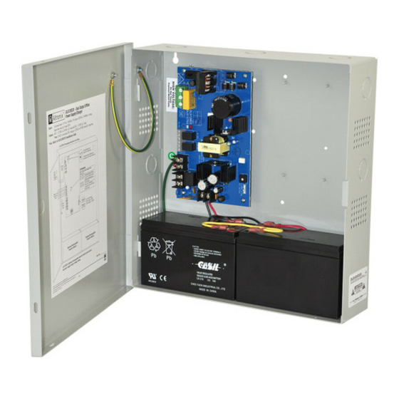
Altronix OLS120D2X dual output power supply/charger converts a 115VAC, 50/60Hz or 230VAC, 50/60Hz input to
a 12VDC/24VDC output and a 12VDC fixed output (see specifications). This unit has a wide range of applications
for access control and security system accessories that require additional power.
Input:
• Universal input 115VAC, 50/60Hz, 0.95A or
230VAC, 50/60Hz, 0.6A.
• Input fuse rated @ 5A/250V.
Output:
• DC1: 12VDC or 24VDC @ 3A.
DC2: 12VDC @ 1A.
Note: If DC2 is not used, DC1 rating is
12VDC or 24VDC rated @ 4A max.
• Filtered and electronically regulated output.
• Short circuit and thermal overload protection.
Battery Backup:
• Built-in charger for sealed lead acid or
gel type batteries.
• Maximum charge current 0.7A.
Wiring methods should be in accordance with the National Electrical Code/NFPA 70/NFPA 72/ANSI and with all
local codes and authorities having jurisdiction. Product is intended for indoor use only.
1. Mount unit in the desired location. Mark and predrill holes in the wall to line up with the top two keyholes
in the enclosure. Install two upper fasteners and screws in the wall with the screw heads protruding. Place
CAUTION: De-energize unit prior to servicing.
the enclosure's upper keyholes over the two upper screws; level and secure. Mark the position of the lower
two holes. Remove the enclosure. Drill the lower holes and install three fasteners. Place the enclosure's
upper keyholes over the two upper screws. Install the two lower screws and make sure to tighten all
screws (Enclosure Dimensions, pg. 4). Secure enclosure to earth ground.
2. Slide [Power ON/OFF] switch t o the OFF position (Fig. 1, pg. 3).
3. Set the DC1 output voltage via DIP switch: OFF for 24VDC operation or ON for 12VDC operation
(Fig. 1, pg. 3). DC2 output voltage is fixed at 12VDC operation.
Keep power-limited wiring separate from non power-limited wiring (115VAC/230VAC, 50/60Hz
Ground
Input, Battery Wires). Minimum 0.25" spacing must be provided.
Wire
CAUTION: Do not touch exposed metal parts. Shut branch circuit power before installing or
Strap
(from
servicing equipment. There are no user serviceable parts inside. Refer installation and servicing to
Enclosure
qualified service personnel.
to Door)
4. Connect AC circuit (115VAC or 230VAC, 50Hz/60Hz) as follows: Green branch wire connects to earth
(safety) ground
115/230VAC
Use 18 AWG or larger for all power connections (Battery, DC output).
power mains
Use 22 AWG to 18 AWG for power-limited circuits (AC Fail/Low Battery reporting).
5. Slide [Power ON/OFF] switch t o the ON position (Fig. 1, pg. 3).
6. Measure output voltage across both output terminals marked [– DC1 +], [– DC2 +] before connecting
Circuit
devices. This helps avoiding potential damage.
7. Slide [Power ON/OFF] switch t o the OFF position (Fig. 1, pg. 3).
OLS120D2X
Dual Output
Offline Power Supply/Charger
Installation Guide
Installation Instructions:
ON
Lug
. Line and Neutral to the connector on power supply board marked [L, N] respectively.
LOW BAT
Overview:
Features:
Battery Backup (cont'd):
• Automatic switch over to stand-by battery
when AC fails.
Supervision:
• AC fail supervision (form "C" contacts).
• Low battery supervision (form "C" contacts).
Visual Indicators:
• AC input and DC output LED indicators.
Features:
• Power ON/OFF switch (interrupts mains).
• Includes battery leads.
Enclosure Dimensions (H x W x D approx.):
13.5" x 13" x 3.25" (342.9mm x 330.2mm x 82.6mm)
• Accommodates two (2) 12VDC/7AH batteries.
OFF
Switch disables power
ON
OFF
mains line voltage input.
If stand-by battery (batteries)
connected, the DC output rem
Red Green Power Supply Status
(DC) (AC)
ON
ON
Normal operating condition
ON
OFF
Loss of AC. Stand-by batte
(batteries) supplying power
OFF ON
No DC output.
OFF OFF
Loss of AC. Discharged or
no stand-by battery (batteri
No DC output.
ON
Advertisement
Table of Contents

Related Manuals for Altronix OLS120D2X


Summary of Contents for Altronix OLS120D2X
- Page 1 Installation Guide Overview: Altronix OLS120D2X dual output power supply/charger converts a 115VAC, 50/60Hz or 230VAC, 50/60Hz input to a 12VDC/24VDC output and a 12VDC fixed output (see specifications). This unit has a wide range of applications for access control and security system accessories that require additional power.
- Page 2 DC power is present. Contact rating 1A @ 115VAC / 28VDC. NC, C, NO Low battery threshold: 2VDC output threshold set @ approximately 10.5VDC, 24VDC output threshold set @ approximately 21VDC. – BAT + Stand-by battery connections. Maximum charge rate 0.7A. - 2 - OLS120D2X Installation Guide...
- Page 3 Fig. 1 - OLS120D2X CAUTION: De-energize unit prior to servicing. Ground Switch disables power mains line voltage input. 115/230VAC power mains If stand-by battery (batteries) are connected, the DC output remains on. DC1 Switch Setting Open - 24VDC Switch Cosed - 12V...
- Page 4 1.0” 10.5” (266.7mm) (25.4mm) (25.4mm) Altronix is not responsible for any typographical errors. –––––––––––––––––––––––––––––––––––––––––––––––––––––––––––––––––––––––––––––––––––––––––––––––––––––––––––––––– 140 58th Street, Brooklyn, New York 11220 USA | phone: 718-567-8181 | fax: 718-567-9056 website: www.altronix.com | e-mail: info@altronix.com | Lifetime Warranty IIOLS120D2X - Rev. 042414...
Need help?
Do you have a question about the OLS120D2X and is the answer not in the manual?
Questions and answers