Advertisement
Quick Links
DESCRIPTION
Demonstration circuit 1892A features the
the high efficiency, high density, dual 18A, switch mode
step-down power module regulator. The input voltage is
from 4.5V to 15V. The output voltage is programmable from
0.6V to 1.8V. DC1892A can deliver up to 18A maximum
in each channel. As explained in the LTM4630 data sheet,
output current derating is necessary for certain V
and thermal conditions. The board operates in continuous
conduction mode in heavy load conditions. For high effi-
ciency at low load currents, the MODE jumper (JP1) selects
pulse-skipping mode for noise-sensitive applications or
Burst Mode
operation in less noise-sensitive applications.
®
Two outputs can be connected in parallel for a single 36A
output solution with optional jumper resistors. The board
BOARD PHOTO
DEMO MANUAL DC1892A
High Efficiency, Dual 18A
LTM
4630EV,
allows the user to program how its output ramps up and
®
down through the TRACK/SS pin. The output can be set
up to either coincidentally or ratiometrically track with
another supply's output. Remote output voltage sens-
ing is available for improved output voltage regulation
at the load point. These features and the availability of
, V
the LTM4630EV in a compact 16mm × 16mm × 4.41mm
IN
OUT
LGA package make it ideal for use in many high density
point-of-load regulation applications. The LTM4630 data
sheet must be read in conjunction with this demo manual
for working on or modifying the demo circuit DC1892A.
Design files for this circuit board are available at
http://www.linear.com/demo/DC1892A
L, LT, LTC, LTM, Linear Technology, Linear logo, μModule and Burst Mode are registered
trademarks of Linear Technology Corporation. All other trademarks are the property of their
respective owners.
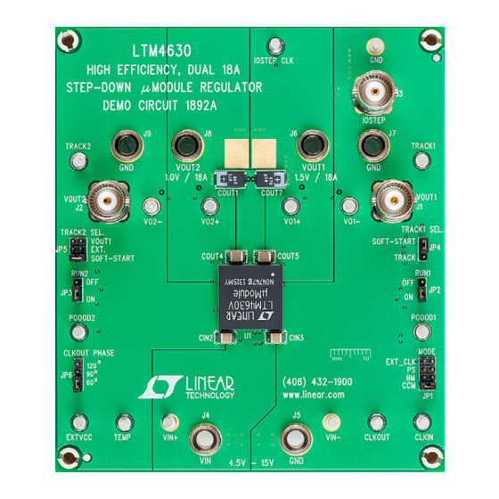
Figure 1. DC1892A
LTM4630EV
Step-Down Power
µModule
Regulator
®
dc1892afb
1
Advertisement

Related Manuals for Linear DC1892A


Summary of Contents for Linear DC1892A
- Page 1 Two outputs can be connected in parallel for a single 36A http://www.linear.com/demo/DC1892A output solution with optional jumper resistors. The board L, LT, LTC, LTM, Linear Technology, Linear logo, μModule and Burst Mode are registered trademarks of Linear Technology Corporation. All other trademarks are the property of their respective owners.
-
Page 2: Quick Start Procedure
OUT2 SETP QUICK START PROCEDURE Demonstration circuit DC1892A is easy to set up to evalu- 5. (Optional) For optional load transient test, apply an ate the performance of the LTM4630EV. Please refer to adjustable pulse signal between the IOSTEP CLK and Figure 2 for proper measurement setup and follow the GND test points. - Page 3 DEMO MANUAL DC1892A QUICK START PROCEDURE – – LOAD LOAD (0A TO 18A) (0A TO 18A) OUT1 OUT1 – – – 4.5V TO 15V – – Figure 2. Test Setup of the DC1892A dc1892afb...
- Page 4 DEMO MANUAL DC1892A QUICK START PROCEDURE = 5V = 12V LOAD CURRENT (A) dc1892a F03 Figure 3. Measured Efficiency on Channel 1. V = 1.5V, OUT1 = 500kHz, Channel 2 Disabled, CCM, 0A to 18A = 5V = 12V LOAD CURRENT (A) dc1892a F04 Figure 4.
- Page 5 DEMO MANUAL DC1892A QUICK START PROCEDURE 9A to 18A LOAD STEP 1.5V OUTPUT (20MHz BW) [50mV/DIV] Figure 5. Measured Channel 1, 9A to 18A Load Transient = 12V, V = 1.5V) OUT1 9A to 18A LOAD STEP 1V OUTPUT (20MHz BW) [50mV/DIV] Figure 6.
- Page 6 DEMO MANUAL DC1892A QUICK START PROCEDURE Figure 7. Thermal Capture at 12V , 1.5V at 18A and OUT1 at 18A (T = 25°C, 200 LFM Airflow and No Heat Sink) OUT2 dc1892afb...
-
Page 7: Parts List
DEMO MANUAL DC1892A PARTS LIST ITEM REFERENCE PART DESCRIPTION MANUFACTURER/PART NUMBER Required Circuit Components CIN2, CIN3, CIN4, CIN5 CAP., X5R, 22µF, 25V, 10%,1210 MURATA, GRM32ER61E226KE15 COUT1, COUT7, COUT9, COUT10 CAP., 470µF, 4V, POSCAP, F8 SANYO, 4TPE470MCL COUT4, COUT5 CAP., X5R, 100µF, 6.3V, 20%, 1210... - Page 8 DEMO MANUAL DC1892A SCHEMATIC DIAGRAM dc1892afb...
-
Page 9: Schematic Diagram
Information furnished by Linear Technology Corporation is believed to be accurate and reliable. However, no responsibility is assumed for its use. Linear Technology Corporation makes no representa- tion that the interconnection of its circuits as described herein will not infringe on existing patent rights. - Page 10 Linear Technology Corporation (LTC) provides the enclosed product(s) under the following AS IS conditions: This demonstration board (DEMO BOARD) kit being sold or provided by Linear Technology is intended for use for ENGINEERING DEVELOPMENT OR EVALUATION PURPOSES ONLY and is not provided by LTC for commercial use. As such, the DEMO BOARD herein may not be complete in terms of required design-, marketing-, and/or manufacturing-related protective considerations, including but not limited to product safety measures typically found in finished commercial goods.
- Page 11 Mouser Electronics Authorized Distributor Click to View Pricing, Inventory, Delivery & Lifecycle Information: Analog Devices Inc. DC1892A...
Need help?
Do you have a question about the DC1892A and is the answer not in the manual?
Questions and answers