Table of Contents
Advertisement
Quick Links
1
st
PRINTING
Sega Amusements Europe Limited.
42 Barwell Business Park, Leatherhead Road, Chessington, Surrey, KT9 2NY. United Kingdom.
Telephone: +44 (0) 208 391 8090
Facsimile:
+44 (0) 208 391 8099
email: mailbox@sega.co.uk
Web: http://www.segaarcade.com
Play It! Amusements, inc.
252 Beinoris Drive, Wood Dale, IL. 60191, USA
USA Sales:
+00 (1) 224 265 4287
© SEGA
IMPORTANT
• Before using this product, read this manual carefully to understand the
contents herein stated.
• After reading this manual, be sure to keep it near the product or in a
convenient place for easy reference when necessary.
Advertisement
Table of Contents

Subscribe to Our Youtube Channel
Related Manuals for Sega PIRATES of MONSTER ISLAND


Summary of Contents for Sega PIRATES of MONSTER ISLAND
- Page 1 PRINTING Sega Amusements Europe Limited. 42 Barwell Business Park, Leatherhead Road, Chessington, Surrey, KT9 2NY. United Kingdom. Telephone: +44 (0) 208 391 8090 Facsimile: +44 (0) 208 391 8099 email: mailbox@sega.co.uk Web: http://www.segaarcade.com Play It! Amusements, inc. 252 Beinoris Drive, Wood Dale, IL. 60191, USA...
- Page 2 BEFORE USING THE PRODUCT , BE SURE TO READ THE FOLLOWING: To maintain safety: To ensure the safe operation of this product, be sure to read the following before usage. The following instructions are intended for the users, operators and the personnel in charge of the operation of the product.
- Page 3 INSPECTIONS IMMEDIATELY AFTER TRANSPORTING THE PRODUCT TO THE LOCATION Normally, at the time of shipment, SEGA products are in a status allowing for usage immediately after transporting to the location. Nevertheless, an irregular situation may occur during transportation. Before turning on the power, check the following points to ensure that the product has been transported in a satisfactory status.
-
Page 4: Introduction
This manual is intended to provide detailed descriptions together with all necessary information covering the general operation of electronic assemblies, electro-mechanicals, servicing control, spare parts, etc. for the product, "PIRATES of MONSTER ISLAND" This manual is intended for the owners, personnel managers in charge of operation of this product. - Page 5 Definition of 'Site Maintenence Personnel or Other Qualified Individuals Procedures not described in this manual or marked as ‘to be carried out by site maintenance personnel or other qualified professionals’ should not be carried out by personnel without the necessary skill or technology. Work carried out by unqualified persons may cause serious accidents, including electrocution.
- Page 6 The WEEE (Waste of Electrical and Electronic Equipment) directive places an obligation on all EU based manufac- turers and importers of Electrical and Electronic Equipment to take back products at the end of their useful life. Sega Amusements Europe Ltd accepts its responsibility to finance the cost of treatment and recovery of redundant WEEE in the United Kingdom in accordance with the specified WEEE recycling requirements.
- Page 7 Notes: Intentionally left blank...
-
Page 8: Table Of Contents
TABLE OF CONTENTS INTRODUCTION HANDLING PRECAUTIONS PRECAUTIONS REGARDING INSTALLATION PRECAUTIONS REGARDING OPERATION PART DESCRIPTIONS ACCESSORIES ASSEMBLY AND INSTALLATION 6-1 INSTALLING THE CABINET 6-2 INSTALLING THE TICKETS 6-3 FIXATION TO SITE 6-4 POWER SUPPLY AND OTHER CONNECTIONS 6-5 TURNING ON THE POWER PRECAUTIONS WHEN MOVING THE MACHINE 7-1 PRECAUTIONS WHEN MOVING FROM SITE GAME DESCRIPTION... - Page 9 COIN HANDLING 12-1 CLEANING THE COIN SELECTOR 12-2 FAULT FINDING 12-3 ADJUSTING THE PRICE OF PLAY (EXCEL) 12-4 ADJUSTING THE PRICE OF PLAY (VTS) LAMPS AND LIGHTING 13-1 COIN DOOR LAMP 13-2 FLUORESCENT TUBES - BILLBOARD PERIODIC INSPECTION TROUBLESHOOTING 15-1 TROUBLESHOOTING (WHEN NO ERROR MESSAGE IS SHOWN) GAME BOARD RF 8 KEY LED RGB CONTROLLER DESIGN-RELATED PARTS...
-
Page 10: Handling Precautions
SEGA shall not be held responsible for damage, compensation for damage to a third party, caused by specification changes not designated by SEGA. Do not perform any work or change parts not listed in this manual. Doing so may lead to an accident. - Page 11 CONCERNING THE STICKER DISPLAY This SEGA product has stickers attached describing the product manufacture No. (Serial No.) and Electrical Specifi- cations. It also has a Sticker describing where to contact for repair and for purchasing parts.
- Page 12 440-CS0036UK Caution - Epilepsy If you or your child have experienced a convulsive attack, loss of consciousness, etc. due to light stimulus or TV games, or fear that you might experience such symptoms, be very careful of using this machine. If you feel sick while playing the game, immediately discontinue use and take a rest.
-
Page 13: Precautions Regarding Installation
PRECAUTIONS REGARDING INSTALLATION This product is an indoor game machine. Do not install it outside. Even indoors, avoid installing in places mentioned below so as not to cause a fire, electric shock, injury and/or malfunction. Places subject to rain or water leakage, or places subject to high humidity in the proximity of an indoor swimming pool and/or shower, etc. - Page 14 Securing a safe area for operation as described in this manual will ensure safe operation for players and observers. SEGA shall not be held responsible for damage or compensation for damage to a third party, resulting from the failure to observe this instruction.
- Page 15 To install this product, the entrance must be at least 0.88m in width and 2.14 m in height. Do not attempt to push/pull the machines whilst holding onto the Controller or Assy Billboard. This may result in part damage and or personal injury. 2.14m 0.88m...
-
Page 16: Precautions Regarding Operation
PRECAUTIONS REGARDING OPERATION To avoid injury and trouble, be sure to pay attention to the behavior of visitors and players. In order to avoid accidents, check the following before starting the operation: • To ensure maximum safety for the players and the customers, ensure that where the product is operated has sufficient lighting to allow any warnings to be read. Operation under insufficient lighting can cause bodily contact with each other, hitting accident, and/or trouble between customers. • Be sure to perform appropriate adjustment of the display (LCD, Plasma, CRT or Projector). For operation of this machine, do not leave monitor's flickering or deviation as is. Failure to observe this can have a bad influence upon the players' or the customers' physical conditions. - Page 17 • To avoid electric shock, ensure that all covers and panels are undamaged and fitted. Do not operate with covers removed. • To avoid electric shock, short circuit and/or parts damage, do not put the following items on or in the periphery of the product. • Flower vases, flowerpots, cups, water tanks, cosmetics, and receptacles/ containers/vessels containing chemicals and water. • To avoid injury, be sure to provide sufficient space by considering the potentially crowded situation at the installation location. Insufficient installation space can cause making bodily contact with each other, hitting accidents, and/or trouble between customers. • Everyday when cleaning the Controller, inspect the controller and make sure that there are no cracks in the surface, and that the fastening screws are not loose. If the game is played with cracks or loose screws, it can cause injuries to the player. • It is recommended that wet towels (paper towels) be provided.
- Page 18 DURING OPERATION (PAYING ATTENTION TO CUSTOMERS) To avoid injury and trouble, be sure to constantly give careful attention to the behavior and manner of the visitors and players. • For safety reasons, do not allow any of the following people to play the game. • Those who have high blood pressure or a heart problem. • Those who have experienced muscle convulsion or loss of consciousness when playing video games, etc. • Those who have neck or spinal cord problems. • Those who are intoxicated or under the influence of drugs. • Pregnant women. • Those who are not in good health.
-
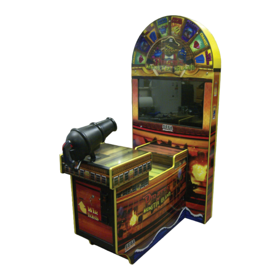
Page 19: Part Descriptions
PART DESCRIPTIONS Billboard Plate Assy LCD Display Speakers Ticket Dispenser LED (WAVE) LED (WAVE) Assembly Billboard Service Door (REAR TOP) Service Door (REAR LWR) Assy AC Unit Speakers Assy Controller Service Door (FRONT) LED (WAVE) -
Page 20: Accessories
ACCESSORIES Confirm that the accessories listed in the table below are present when setting up the product. Accessories marked “Spare” in the note column are consumable items but included as spares. 440-CS0186UK Sticker C Epilepsy Multi (1) DESCRIPTION: OWNER’S MANUAL Part No. -
Page 21: Assembly And Installation
ASSEMBLY AND INSTALLATION • Perform assembly work by following the procedure herein stated. Failure to comply with the instructions can cause electric shock. • Perform assembly as per this manual. Since this is a complex machine, incorrect assembling can cause an electric shock, machine damage and/or improper functioning as per specified performance. • When assembling, more than one person is required. Depending on the assembly work, there are some cases in which working by one person alone can cause personal injury or parts damage. • Ensure that connectors are properly connected. Improper connections can cause electric shock. • Be careful not to damage the wires. Damaged wires may cause electric shock or short circuit or present a risk of fire. • Do not unnecessarily push the display screen. • This work should be carried out by site maintenance personnel or other qualified professionals. Work performed by non-technical personnel can cause a severe accident such as electric shock. Failing to comply with this instruction can cause a severe accident such as electric shock to the player during operation. If no one with proper technological expertise is available, request service from the office indicated in this document or the point of purchase so as to ensure safety. • Provide sufficient space so that assembling can be performed. Performing work in places with narrow space or low ceiling may cause an accident and assembly work to be difficult. • To perform work safely and avoid serious accident such as the cabinet falling down, do not perform work in places where step-like grade differences, a ditch, or slope exist. • This product does not use any connectors other than those connected to and used by the game board when it leaves the factory. Do not needlessly connect wires to unused connectors. This could lead to overheating, generation of smoke and burn related injuries. -
Page 22: Installing The Cabinet
INSTALLING THE CABINET • Billboard weighs approximately 19 kg. Have at least 2 people during this operation. Working alone could result in personal injuries, etc. • To perform work safely and securely, be sure to prepare a step which is in a safe and stable condition. Performing work without using a step may lead to injury of damage to components. Tools required for installation Allen Key (M5) - Attaching Billboard Panel to Assy Billboard. - Page 23 6-1-1 INSTALLING THE ASSY BILLBOARD Locate the 2 Billboard brackets and make sure that they have not sustained any damage during transportation. Lossen the 4 fixings so that the brackets are not tight against the cabinet Unpack the Billboard and remove the 4x M4 machine screws located at the Billboard sides.
- Page 24 Unpack the Billboard Plate taking care not to damage the Lamp Holder which secures the lamp for the Pirates Eye. Locate and remove the 6 sets of fixings from the Plate fixing points within the Bilboard. Next offer the Billboard Plate up to the Billboard and connect the Lamp in to the trailing harness within the Billboard. Secure the Billboard Plate in place.
-
Page 25: Installing The Tickets
INSTALLING THE TICKETS This game has a functional Ticket Unit installed. Please follow the instructions below on how to install tickets into the Ticket Unit. Open the front door to allow access tot he ticket unit. Unlock & Open Front Door Place the Tickets into the TICKET HOLDER. - Page 26 Press the TEST button on the side of the VEND MECH PCB to check that the Tickets run smoothly through the unit. Once the tickets have been fully inserted into the mech, replace the ticket retainer to secure tickets into position. Press the TEST button on the PCB to draw tickets through the mech and out of the door.
-
Page 27: Fixation To Site
FIXATION TO SITE • Make sure that all the adjusters contact the floor. Otherwise the cabinet could move, causing an accident. • Provide a ventilation space at least 15cm wide behind the cabinet. There are ventilation holes on the back of the cabinet. Do not block the ventilation holes. Doing so could trap heat inside resulting in fire. It could also result in equipment damage or cause parts to become exhausted prematurely. The product is equipped with 4 casters and 4 adjusters. When installation position / site has been determined, have the adjusters come in direct contact with the floor. - Page 28 • Provide a ventilation space at least 20cm wide behind the cabinet. There are ventilation holes on the back of the cabinet. Do not block the ventilation holes. Doing so could trap heat inside resulting in fire. It could also result in equipment damage or cause parts to become exhausted prematurely. 150mm Leave a 150mm gap for ventilation...
-
Page 29: Power Supply And Other Connections
POWER SUPPLY AND OTHER CONNECTIONS • Use the power supply equipped with an earth leakage breaker. Use of power supply without such a breaker could result in fire if there is a current leakage. • Have available a securely grounded indoor ground terminal. Without proper grounding, customers could be electrocuted and product operations might not always be stable. • Do not expose the power cord or ground wire. If these are exposed, customers could stumble over them, for instance, and easily damage them. Additionally, if these lines are damaged, there could be a risk of electrical shock or short circuit. -
Page 30: Turning On The Power
Fully insert the power cord connector on the side opposite the power plug into the AC unit IEC inlet. Insert the power cord plug into the outlet. The power code is laid out indoors. Protect the power cord by attaching wire cover to it. WIRE COVER TURNING ON THE POWER Set the main switch of the AC unit to ON and engage the power. - Page 31 COMPONENTS WHICH CHANGE STATE WHEN POWER IS APPLIED Billboard illumination Attract Sequence Audio output Coin IN Lamp Audio output LED output...
-
Page 32: Precautions When Moving The Machine
PRECAUTIONS WHEN MOVING THE MACHINE • Always disconnect the power cable before moving the product. If it is moved with the power cable connected, the cable could be damaged, causing fire or electric shock. • To move the unit over the floor, pull in the adjustors and have the casters contact the floor. While moving the unit, be careful that the casters do not roll over the power cord or the ground wire. If cord or wire is damaged, there could be electrical shocks and/or short circuits. -
Page 33: Precautions When Moving From Site
PRECAUTIONS WHEN MOVING FROM SITE • When moving the cabinet, do not grip or push the Billboard Plate. Doing so could deform or damage the part. • If moving through a door or place with a low ceiling such as an elevator, you should take apart the billboard and billboard plate. Detailed instructions for removing the Assy Billboard and Billboard Plate can be found in Chapter 6 of this manual. Please follow these instruction in reverse order for removal. Ensure that the casters come into contact with the floor before moving. -
Page 34: Game Description
GAME DESCRIPTION GAME OUTLINE Pirates Of Monster Island is a physics based redemption shooting game. Players must use their skill to aim and time their shots to knock items into the sea from passing ships. Tickets are paid out to the player as soon as they are awarded the game play is of a continuous nature. - Page 35 DRAGONS DEN FEATURE The Dragons Den Gauge, located on the left hand side of the screen is filled by the player knock- ing coloured standard boxes into the sea. The gauge has an optional numerical counter that can be disabled in the test menu. This gauge is persistent across credits but will slowly decrease over time.
-
Page 36: Explanation Of Test And Data Display
EXPLANATION OF TEST AND DATA DISPLAY Perform tests and data checks periodically by manipulating the TEST Button and SERVICE Button in the cabinet. Follow the instructions in this chapter to conduct checks when the game machine is first installed, when money is being collected, or when the game machine does not operate properly. -
Page 37: Switch Unit And Coin Meter
9-1 SWITCH UNIT AND COIN METER. Never touch places other than those specified. Touching places not specified can cause electric shock and short circuit accidents. • Adjust the sound to the optimum volume, taking into consideration the environmental requirements of the installation location. • Removing the Coin Meter circuitry renders the game inoperable. 9-1-1 SWITCH UNIT Open the coin chute door, and the switch unit shown will appear. The functioning of each SW is as follows: Coin Counter Game Counter (not used) Volume Control... -
Page 38: Test Mode
9-2 TEST MODE The details of changes to Test Mode settings are saved when you exit from each Test Mode by selecting EXIT. Be careful because if the power is turned off before that point, changes to the settings will be lost. Opens the Game Test Mode, allowing game specific settings and tests to be performed. This option will be displayed in grey until preparations are complete. Select the Game Test Mode option to begin the game test. TEST MODE I/O CHECK GUN CHECK... -
Page 39: I/O Check
9-3 I/O CHECK INPUT CHECK Using the SERVICE button to select I/O CHECK and press the TEST button to enter the selected item. TEST MODE I/O CHECK GUN CHECK SCREEN CHECK GAME OPTIONS SOUND OPTIONS COIN OPTIONS TICKET OPTIONS BOOKKEEPING ALL FACTORY SETTINGS GAME MODE SELECT MENU : SERVICE EXECUTE : TEST... - Page 40 OUTPUT CHECK Use the SERVICE button to select OUTPUT CHECK and press TEST to execute. I/O CHECK INPUT CHECK OUTPUT CHECK EXIT SELECT MENU : SERVICE EXECUTE : TEST This test is used to check the System Output on the Lamps in the cabinet. Use the SERVICE button to move the cursor to the desired test item.
-
Page 41: Gun Check
9-4 GUN CHECK Use the SERVICE button to select GUN CHECK and press TEST to execute. TEST MODE I/O CHECK GUN CHECK SCREEN CHECK GAME OPTIONS SOUND OPTIONS COIN OPTIONS TICKET OPTIONS BOOKKEEPING ALL FACTORY SETTINGS GAME MODE SELECT MENU : SERVICE EXECUTE : TEST Use the SERVICE button to select CALIBRATION and press TEST to execute. -
Page 42: Screen Check
9-5 SCREEN CHECK Use the SERVICE button to select SCREEN CHECK and press TEST to execute. TEST MODE I/O CHECK GUN CHECK SCREEN CHECK GAME OPTIONS SOUND OPTIONS COIN OPTIONS TICKET OPTIONS BOOKKEEPING ALL FACTORY SETTINGS GAME MODE SELECT MENU : SERVICE EXECUTE : TEST Use the SCREEN CHECK to check the setting on the LCD display and make any adjustments to suit the enviroment, e.g light conditions. -
Page 43: Game Options
9-6 GAME OPTIONS Use the SERVICE button to select GAME OPTIONS and press TEST to execute. TEST MODE I/O CHECK GUN CHECK SCREEN CHECK GAME OPTIONS SOUND OPTIONS COIN OPTIONS TICKET OPTIONS BOOKKEEPING ALL FACTORY SETTINGS GAME MODE SELECT MENU : SERVICE EXECUTE : TEST Use the SERVICE button to highlight each game option and press TEST ammend value. -
Page 44: Sound Options
9-7 SOUND OPTIONS Use the SERVICE button to select SOUND OPTIONS and press TEST to execute. TEST MODE I/O CHECK GUN CHECK SCREEN CHECK GAME OPTIONS SOUND OPTIONS COIN OPTIONS TICKET OPTIONS BOOKKEEPING ALL FACTORY SETTINGS GAME MODE SELECT MENU : SERVICE EXECUTE : TEST Use the SERVICE button to select SOUND OPTIONS and press TEST to execute. -
Page 45: Coin Options
9-8 COIN OPTIONS Use the SERVICE button to select COIN OPTIONS and press TEST to execute. TEST MODE I/O CHECK GUN CHECK SCREEN CHECK GAME OPTIONS SOUND OPTIONS COIN OPTIONS TICKET OPTIONS BOOKKEEPING ALL FACTORY SETTINGS GAME MODE SELECT MENU : SERVICE EXECUTE : TEST Use the SERVICE button to highlight each option and press TEST ammend value. -
Page 46: Ticket Options
9-9 TICKET OPTIONS Use the SERVICE button to select TICKET OPTIONS and press TEST to execute. TEST MODE I/O CHECK GUN CHECK SCREEN CHECK GAME OPTIONS SOUND OPTIONS COIN OPTIONS TICKET OPTIONS BOOKKEEPING ALL FACTORY SETTINGS GAME MODE SELECT MENU : SERVICE EXECUTE : TEST TICKET OPTIONS configures the settings for redemption tickets. -
Page 47: Bookkeeping
9-10 BOOKKEEPING Use the SERVICE button to select BOOKKEEPING and press TEST to execute. TEST MODE I/O CHECK GUN CHECK SCREEN CHECK GAME OPTIONS SOUND OPTIONS COIN OPTIONS TICKET OPTIONS BOOKKEEPING ALL FACTORY SETTINGS GAME MODE SELECT MENU : SERVICE EXECUTE : TEST View the history of game play and change time and date. - Page 48 VIEW BOOKKEEPING Visual display of the machine bookkeeping records. BOOKKEEPING COIN IN SERVICE COIN IN 18 TOTAL PLAYS INITIAL START TOTAL PLAY TIME 0h18m18s AVERAGE PLAY TIME 0m27s SHORTEST PLAY TIME 0m01s LONGEST PLAY TIME 1m51s INCOME HISTORY TODAY YESTERDAY 2 DAYS AGO 3 DAYS AGO 4 DAYS AGO...
-
Page 49: All Factory Settings
9-11 ALL FACTORY SETTINGS Use the SERVICE button to select ALL FACTORY SETTINGS and press TEST to execute. TEST MODE I/O CHECK GUN CHECK SCREEN CHECK GAME OPTIONS SOUND OPTIONS COIN OPTIONS TICKET OPTIONS BOOKKEEPING ALL FACTORY SETTINGS GAME MODE SELECT MENU : SERVICE EXECUTE : TEST Will rest all setting made with the exception of the following: BOOKKEEP DATA... -
Page 50: Controller Unit(S), Switches And Buttons
CONTROLLER UNIT(S), SWITCHES AND BUTTONS • When working with the product, be sure to turn the power off. Working with the power on may cause an electric shock or short circuit. • Be careful not to damage the wires. Damaged wires may cause an electric shock, short circuit or present a risk of fire. • Exercise due caution in performing soldering work. If soldering iron is handled carelessly, there could be fires or burns. • When fastening plastic parts, be careful not to tighten screws or nuts excessively. If these are tightened to excess, parts could be damaged, resulting in injuries from fragments, etc. • After the unit has been disassembled and reassembled again, check carefully that the unit has been reassembled correctly. • Be sure to inspect the outer covers on both gear and hand brake units. • Assemble so that there is no gap between the L and R covers. If there is a gap or rattling, the players could get fingers or hands caught, resulting in injury. • Once the product has been disassembled, use slack preventive agent (product No. : 090-0012-N). Coat screws with suitable amounts of this agent and then tighten them. If this agent is not used, the product might start rattling or come apart. • Use the slack preventive agent prescribed in these instructions. If any other agent is used, there could be chemical changes that inhibit the use of screws and part surfaces could be damaged. • Be careful not to damage or lose small parts or screws. • When a part has been replaced, be sure to always make adjustments and check conditions in Test Mode. -
Page 51: Removing The Controller
10-1 REMOVING THE CONTROLLER Be sure to disconnect the power from the machine before performing any work. Failure to remove the power may result in electric shock or component damage. Turn off the power. Remove the 2x screws from the small finger trap plate located at the front of the Canon base. Remove plate. REMOVE FIXINGS SMALL FINGER TRAP PLATE Remove the 2 screws from the finger trap plate located at the rear base of the controller. Remove plate. REAR FINGER TRAP PLATE REMOVE FIXINGS... - Page 52 Remove the 4 screws which secure the Control Panel to the cabinet. REMOVE FIXINGS REMOVE FIXINGS Carefully slide out the Controller Base and Control Panel in opposite directions as illustrated. Remove the 4x M8 Hex Bolts located at the base of the Controller. Take care in disconnecting the Controller Harness and remove the controler.
-
Page 53: Adjusting/Replacing The Volume Pot
Be sure to perform volume's move value setting in the INPUT ASSIGNMENTS in the Game Test Mode after replacing or adjusting the Volume. 10-2 ADJUSTING/REPLACING THE VOLUME POT ADJUSTMENT PROCEDURE LOOSEN FIXINGS H VOLUME BKT V VOLUME BKT Apply this procedure to both Horizontal and Vertical Volume Pots. Loosen the 2 screws that secure the VR Bracket and move the VR Bracket to adjust the angle and condition of the gear alignment. Locate the central position of the pot by turning the pot in both clockwise ans counterclockwise positions. Once a central position of the pot has been determined, straighten the handle so that the gear is positioned horizontally. Slide the pot into position engaging the gears. Tighten the 2 screws and secure the VR Bracket and refit the cover. Check to make sure the value on the Input Test screen is within the range 80H ± 8H when the steering unit is in the straight position. - Page 54 REPLACEMENT PROCEDURE This procedure requires the following tools: Phillips screwdriver for the M4 screws, 1.5 mm hexagonal wrench, 11- 12 mm monkey wrench, nipper, cutter, wire stripper, soldering iron, industrial dryer and heat-shrinkable tube. Remove the connectors. Remove the 2 screws securing the VR Bracket and remove the entire Bracket and V.R. (See previous instruction) Loosen the 1 hexagon socket screws on the Gear Holder and remove the Gear Holder. Remove the nut securing the VR Bracket, then separate the Volume from the VR Bracket and replace it. Check to make sure the value on the Input Test screen is within the range 80H ± 8H when the steering unit is in the straight position. VOLUME POT VOLUME POT WSHR VOLUME POT NUT VOLUME POT BKT VOLUME POT GEAR HEX SOCKET SCREW...
- Page 55 The wire connected to the volume pot will be reused. Use a tool such as a pair of snips or cutters to remove the old heatshrink tubes which cover the contacts. Use a soldering iron to melt the solder and seperated the wires from the old volume pot. Be very careful when using a soldering iron. If the exposed conductive wire at the end is less than 5mm, use a tool such as a wire stripper or cutter to cut the wire insulation back to a workable length. Place new sleeving over the wire before resoldering them to the pot. Once soldered, cover the bare contacts with the sleeving. If heatshrink is used, apply heat from an appropriate hot air blower to shrink the sleeving tightly over the contacts. Reassemble the pot to the pot bracket by working in reverse order of these instructions. Refer to the POT VOLUME ADJUSTMENT section of this manual.
-
Page 56: Greasing
10-3 GREASING • Be sure to use the designated grease. Using undesignated grease can cause parts damage. • Do not apply grease to locations other than as specified. Doing so may create a risk of operational problems and deterioration of parts. • The designated periods for greasing serve only as a guide. Whenever there are squeaks or other anomalies, apply grease at designated locations. Use spray grease once every three months to grease up the gear mesh portion of the constituent parts. Use "Grease Mate" (part number 090-0066) for the spray grease. GREASING POINT GREASING POINT... -
Page 57: Lcd Display (Vga)
LCD DISPLAY (VGA) 11-1 SAFETY PRECAUTIONS WHEN HANDLING THE MONITOR Responding to breakdown or abnormality ● If smoke or a strange odor appears, immediately unplug the power cable from the power source. Continuing to use the product may cause a fire or an electric shock. Ensure that smoke is no longer emitted, and contact the point of purchase. ● If nothing displays on the screen, immediately unplug the power cable from the power source. Continuing to use the product may cause a fire or an electric shock. Contact the point of purchase and request an inspection. ● If water or a foreign object enters the monitor’s interior, immediately unplug the power cable from the power source. Continuing to use the product may cause a fire or an electric shock. Contact the point of purchase and request an inspection. ● If the monitor is dropped or the cabinet is damaged, immediately unplug the power cable from the power source. Continuing to use the product may cause a fire or an electric shock. Contact the point of purchase and request an inspection. During operation ● Do not repair, reconstruct, or disassemble the monitor. The monitors interior contains high voltage parts. A fire or an electric shock could result. For inspections, adjustments, and repair of the monitors interior, request work from the point of purchase. - Page 58 11-2 CLEANING THE SCREEN SURFACE ● Use a soft, dry cloth (flannel-type) to wipe away dirt. Do not use materials such a s coarse mesh gauze. ● Alcohol (ethanol) is the recommended solvent for removing dirt. When using a c leaning agent, follow the precautions below. - Dilute neutral cleaning agents for home use with water. Soak a soft cloth in the s olution, and wring it thoroughly before wiping the screen. - Do not use abrasive cleaning agents or powders, or cleaning agents c ontaining bleach. - Do not use alkaline cleaning agents such as glass cleaners, or solvents such as t hinners. ● Do not scrub or scratch the screen surface with abrasive materials such as b rushes or scrub brushes. CLEAN THE SCREEN DAILY.
- Page 59 11-3 ADJUSTMENT METHOD All adjustment values are set accurately at the time of shipping from the factory. Do not readjust these values needlessly or apply adjustments not specified in this manual. The display may not appear properly if the values are incorrect.
- Page 60 11-3 ADJUSTMENT METHOD Button Names and Functions 11-3 Fig. 03 MENU: Turn the Picture Menu display ON and OFF. SELECT: Gains entry to the Item selected in the menu. (Highlights in Yellow when selected) Exits the Item adustment. Any changes made during this operation are actioned.
- Page 61 11-3 ADJUSTMENT METHOD On-Screen Display (OSD) Press the MENU Button while the OSD is not displayed to bring up the Picture Menu. On the Picture Menu, it is possible to perform various screen adjustments. 11-3 Fig. 04 Use the UP and DOWN Buttons to move the ‘Black Bar’to the item you want to adjust. After selecting the desired item, pressing the SELECT Button will extend the MENU Screen and allow adjustments to be changed.
- Page 62 11-3 ADJUSTMENT METHOD On-Screen Display (OSD) <continued> 11-3 Fig. 06 Available Settings (Selects Operation Mode)) Selection availble - 6500K - 9300K - USER BRIGHTNESS (Adjust Brightness) Adjust screen Brightness. - Values: 0 - 100 (0” being the darkest setting, and “100” being the brightest) CONTRAST (Adjust Contrast) Adjust Contrast level.
-
Page 63: Coin Handling
COIN HANDLING Handling the Coin Jam If the coin is not rejected when the REJECT button is pressed, open the coin chute door and open the selector gate. After removing the jammed coin, put a normal coin in and check to see that the selector correctly functions. 12-1 CLEANING THE COIN SELECTOR ● Remove and clean smears by using a soft cloth dipped in water or diluted chemical... - Page 64 CLEANING THE COIN SELECTOR (MECHANICAL). Remove and clean smears by using a soft cloth dipped in water or diluted chemical detergent and then squeezed dry. Remove the CRADLE.. When removing the retaining ring (E ring) be very careful so as not to bend the rotary shaft.
- Page 65 CLEANING THE COIN SELECTOR (SR3) <continued> Remove and clean smears by using a damp soft cloth dipped in water. DO NOT use any diluted chemical detergent or cleansing agent as this will impair the workings of the component. GATE Open the reject gate to gain access to the rundown path.
-
Page 66: Fault Finding
12-2 FAULT FINDING Fault Finding The following information is presented for customers’ guidance in rectifying a fault but does not cover all possible causes. All acceptors with electronic faults should be returned to an approved service centre for repair. SYMPTOM INVESTIGATE POSSIBLE CAUSE Poor Contact... -
Page 67: Adjusting The Price Of Play (Excel)
12-3 ADJUSTING THE PRICE OF PLAY (EXCEL) ● The price of play is determined by the configuration of switches located on either an EXCEL board or VTS board. The type of board used is determined by product location. Switch settings for both types of board remain the same. This product comes equipped with a Money Controls SR3 Coin Acceptor. To adjust the price of play ALL credit setting are adjusted via the EXCEL CREDIT BOARD. -
Page 68: Adjusting The Price Of Play (Vts)
12-4 ADJUSTING THE PRICE OF PLAY (VTS) This product comes equipped with a Money Controls SR3 Coin Acceptor. To adjust the price of play ALL credit setting are adjusted via the EXCEL CREDIT BOARD. IMPORTANT! The CREDIT SETTINGS within the SYSTEM TEST MODE must be set to 1 coin 1 credit to allow the CREDIT BOARD to function correctly. - Page 69 REGIONAL AND ACCEPTOR SETTINGS (SW3)
- Page 70 STERLING PRICE OF PLAY SETTINGS (SW1)
- Page 71 EURO PRICE OF PLAY SETTINGS (SW1)
-
Page 72: Lamps And Lighting
LAMPS AND LIGHTING • When working with the product, be sure to turn the power off. Working with the power on may cause an electric shock or short circuit. • You may get burned by a hot fluorescent lamp or other lamps. Pay full attention to the lamps when performing the work. -
Page 73: Fluorescent Tubes - Billboard
13-2 FLUORESCENT TUBES - BILLBOARD THIS WORK ON TOP OF THE CABINET, SHOULD NOT BE UNDERTAKEN WITHOUT THE USE OF A SUITABLE STEP OR FOOTSTOOL. TURN THE POWER OFF. Remove the Billboard plate by following the BILLBOARD INSTALLATION GUIDE in reverse on Chapter 2 of this manual. - Page 74 LED (PIRATES EYE) TURN THE POWER OFF. Remove the Billboard plate by following the BILLBOARD INSTALLATION GUIDE in reverse on Chapter 2 of this manual. The LED PIRATES EYE is mounted to the rear of the BILLBOARD PLATE. Diconnect LED PIRATES EYE LED harness before removal. Lamp Holder Bracket Lamp Holder LED RED Pt No LT1055...
- Page 75 BASE (WAVE LED’S) THIS WORK MAY REQUIRE LIFTING THE CABINET OR PLACING THE CABINET ON ITS SIDE IN ORDER TO GAIN ACCESS TO THE LED STRIP BRACKET FIXINGS. WHEN LIFTING THE CABINET, ALWAYS DO SO BY USING SUITABLE LIFTING EQUIPMENT. NEVER ATEMPT TO BALANCE THE CABINET AGAINST ANOTHER SURFACE IN ATEMPT TO GAIN ACCES TO THE FIXINGS ON THE UNDERSIDE OF THE CABINET.
- Page 76 Locate and unscrew the fixings (5), remove the bracket taking care not to damage the harness which is connected to the cabinet The WAVE LED strips are self adhesive flei strip Pt No: PG-60020-750BUK LED STRIP ASSY Pt No: PG-60020-750BUK Philips Machine Screw (5) Carefully peel away the old LED Strip and adhere the replacement in an identical location.
-
Page 77: Periodic Inspection
PERIODIC INSPECTION The items listed below require periodic check and maintenance to retain the performance of this machine and to ensure safe business operation. When handling the controller, the player will be in direct contact with it. In order to always allow the player to enjoy the game, be sure to clean it regularly. - Page 78 Cleaning the Cabinet Surfaces When the cabinet surfaces are badly soiled, remove stains with a soft cloth dipped in water or diluted (with water) chemical detergent and squeezed dry. To avoid damaging surface finish, do not use such solvents as thinner, benzine, etc.
-
Page 79: Troubleshooting
TROUBLESHOOTING 15-1 TROUBLESHOOTING (WHEN NO ERROR MESSAGE IS SHOWN) • In order to prevent electric shock and short circuit, be sure to turn power off before performing work. • Be careful so as not to damage wirings. Damaged wiring can cause electric shock or short circuit. - Page 80 Sound is not emitted. Sound volume adjustment is not Adjust the Switch Unit’s sound correct adjustment volume. Faulty connections for various Check the connections for the game connectors board, amp, speakers and Volume connectors Malfunctioning BD, amp and speaker Perform Sound Test. Sounds are emitted and Faulty connections for the visual Check the connections for the monitor...
-
Page 81: Game Board
GAME BOARD ● When working with the product, be sure to turn the power off. Working with the power on may cause an electric shock or short circuit. ● Be careful not to damage the wires. Damaged wires may cause an electric shock, short circuit or present a risk of fire. ● Do not use this product with connectors other than those that were connected and used with the game board at the time of shipping. Do not carelessly connect wires to connectors that were not used at the time of shipping, as this may cause overheating, smoke or fire damage. In this product, setting changes are made during the test mode. The game board need not be operated. Use the game board, etc. as is with the same setting made at the time of shipment so as not to cause electrical damage or malfunction. Static electricity from your body may damage some electronics devices on the IC board. Before handling the IC board, touch a grounded metallic surface so that the static electricity can be discharged. - Page 82 16-1 GAME BOARD - LOCATION & REMOVAL ● When returning the game board after making repairs or replacements, make sure that there are no errors in the connection of connectors. Erroneous connections can lead to electrical shock, short circuits or fires. ● When connecting a connector, check the direction carefully. Connectors must be connected in only one direction. If indiscriminate loads are applied in making connections, the connector or its terminal fixtures could be damaged, resulting in electrical shock, short circuits or fires. The machine is fitted with Game Board Unit and several other Ancillary Boards which are fitted inside the Display Cabinet.
- Page 83 The GAME BD is mounted on a wooden Base. To remove the GAME BD, disconnect ALL connections to the GAME BD, unscrew the single fixing which secures the wooden base to the cabinet and carefully slide out the ASSY GAME BD from within the cabinet. GAME BOARD Slide out Not Used...
-
Page 84: Rf 8 Key Led Rgb Controller
RF 8 KEY LED RGB CONTROLLER RF 8 key LED RGB Controller Control method Adopt film button control and RF control, each film button function as follows,remarked in bracket is RF button’s: ON/OFF:In any state,you could turn on or turn off the output of controller; PAUSE:when you want to see the static effection of led ,you may press this button to pause. -
Page 85: Design-Related Parts
DESIGN-RELATED PARTS For the warning display stickers, refer to Section 1. -
Page 86: Parts List
PARTS LIST 1 ASSY POMI MAIN CABI (PG-1000UK) (D-1/2) ITEM NO PART NUMBER DESCRIPTION PG1001UK ASSY CABI MAIN PG0550UK BILLBOARD BOX POMI PG-1060UK FEATURE WHEEL / BILLBOARD PLATE PG-1005UK SAFETY GLASS LCD PG-2000UK ASSY CONTROLLER PG-1280UK ASSY LCD DISPLAY... - Page 87 2 ASSY POMI MAIN CABI (PG-1000UK) (D-2/2) 7 23 24 ITEM NO PART NUMBER DESCRIPTION PG-1540UK AC UNIT FN1012 FAN GUARD METAL 260-0012-01UK FAN GUARD METAL 105-5340-01 FAN BKT LONG...
- Page 88 3 ASSY FRONT DOOR (D-1/1) ITEM NO PART NUMBER DESCRIPTION 130-008-08015WP SPEAKER 220-5610-01 NRI COIN ACCEPTOR 220-5786-R A0710 IL FRONT PLATE PG-1107UK BRKT RETAIN TICK HOLDER MICROSWITCH PG-1106UK TICKET HOLDER 220-0001-01UK TICKET VEND UNIT PG-1108UK PLATE MOUNT COIN MECH...
- Page 89 4 ASSY SW UNIT (PG-0320UK) (D-1/1) ITEM NO PART NUMBER DESCRIPTION 220-5643UK COIN METER SMALL 838-14548-01UK SW & C VOL BD EP1380-01 EXCEL CREDIT BD SSR-0321UK SW BKT DOUBLE METER...
-
Page 90: Wire Colour Code Table
WIRE COLOUR CODE TABLE The DC power wire color for this product is different from previous SEGA titles. Working from the previous wire colors will create a high risk of fire. The color codes for the wires used in the diagrams in the following chapter are as follows. -
Page 91: Schematic Diagrams
(D-1/3) SCHEMATIC DIAGRAMS... - Page 92 (D-2/3)...
Need help?
Do you have a question about the PIRATES of MONSTER ISLAND and is the answer not in the manual?
Questions and answers