Table of Contents
Advertisement
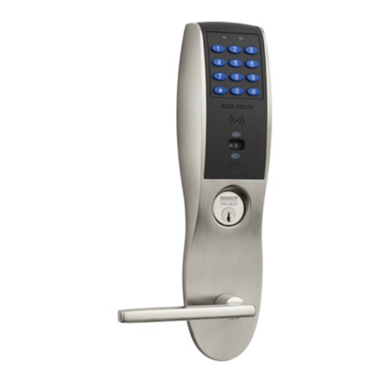
PR100
with Aperio
Wireless Lock
Technology
Exit Device
Installation Instructions
A8080D (N2)
8/12
Copyright 2012, Sargent Manufacturing Company, an ASSA ABLOY Group company.
All rights reserved. Reproduction in whole or in part without the express written
permission of Sargent Manufacturing Company is prohibited.
™
Advertisement
Table of Contents

Related Manuals for Assa Abloy Sargent PR100


Summary of Contents for Assa Abloy Sargent PR100
- Page 1 Wireless Lock Technology Exit Device Installation Instructions A8080D (N2) 8/12 Copyright 2012, Sargent Manufacturing Company, an ASSA ABLOY Group company. All rights reserved. Reproduction in whole or in part without the express written permission of Sargent Manufacturing Company is prohibited.
-
Page 2: Table Of Contents
Table of Contents Warning ...................2 General Description ..............3 Hardware Specifications ............3 Electronic Specifications ............3 System Overview ..............3 Aperio With 8877/8878 Rim Exit ..........4 Aperio With 8977/8978 Mortise Exit .......... 14 Operational Check ..............24 Lock LED Indications ............25 Warning: Changes or modifications to this device not expressly approved by ASSA Warning ABLOY could void the user’s authority to operate the equipment. -
Page 3: General Description
PR100 Exit Devices General Description The SARGENT ® PR100 lock with Aperio™ Technology makes it easy and cost-effective to bring access control to additional doors. It uses local wireless communication between the lock and an Aperio hub to connect to an access control system, eliminating the greatest cost and inconvenience of traditional access control –... -
Page 4: Aperio With 8877/8878 Rim Exit
PR100 Exit Devices Aperio with 8877/8878 Rim Exit Parts Breakdown for Aperio With 8877/8878 x ET x Lever Design 13.56 MHz iCLASS & 125 kHz Prox... - Page 5 PR100 Exit Devices Parts Breakdown Aperio with 8877/8878 Rim Exit (Continued) 13.56 MHz iCLASS & 125 kHz Prox ITEM PART NO. DESCRIPTION QTY. N2-777- 8-HAND-FINISH N2 Series ET Trim - With Cylinder N2-778-8-HAND-FINISH N2 Series ET Trim - Without cylinder ET Lever Reference 8800 Series Catalog for Available Levers 68-1397...
- Page 6 PR100 Exit Devices Lock Installation 1 Prepare Door A. Verify Hand and Bevel of Door Inside • This device is non-handed. • Door should be fitted and hung. • Verify box label for size of exit device and function. Left Hand Right Hand Reverse Bevel Reverse Bevel...
- Page 7 PR100 Exit Devices 3 Secure Inside Trim and Chassis 1. Route ET harness through wire run channel for wood doors (Fig. 3A) and through access hole for metal doors (not shown). Note: Make sure no wires are pinched. 2. Engage ET spindle in the hub of exit device chassis.
- Page 8 PR100 Exit Devices 4 Install Cylinder and Secure Chassis For devices without cylinder, skip this step. 1. Insert cylinder into ET trim (Fig. 4). 2. Mate cylinder tailpiece with hub of exit device chassis. 3. Make sure ET harness is clear of cylinder and cylinder tailpiece. Fig.
- Page 9 PR100 Exit Devices 7 Install Door Position Switch (DPS) 1. Insert DPS into the raceway on the latch edge of the door. 2. Push wires through raceway toward lock prep. 3. Push DPS firmly into place by hand. Note: DO NOT TAP SWITCH WITH ANY TOOL. 4.
- Page 10 PR100 Exit Devices 9 Connect and Position Outside Escutcheon Wires Images shown represent installation without gasket. If gasket is necessary, refer to Step #8. Attach outside escutcheon reader cable to connector P1 on back side of inside escutcheon. Reader Cable Reader Cable Outside Escutcheon Fig.
- Page 11 PR100 Exit Devices 10 Connect and Position Chassis Wires 1. Connector RX harness (3-pin connector) from ET Trim to chassis harness. 2. Attach connector from ET to the controller assembly (TB1). 3. Connect DPS from switch to 3-pin connector of the harness connected to controller assembly (TB2).
- Page 12 PR100 Exit Devices 13 Install (or Replace) Batteries 1. To install the batteries, first remove the battery Battery cover using the security tool provided (Fig. 13A). Cover 2. Unscrew the bottom screw of the battery keeper and remove the battery keeper, being careful not to break the tabs at top holding it in place (Fig.13B) .
- Page 13 PR100 Exit Devices 14 Install Rail Assembly 1. Connect RX harness (3-pin connector) from the rail to the RX harness in the chassis. 2. Attach rail assembly according to Exit Installation Instructions A6770. Fig. 14...
-
Page 14: Aperio With 8977/8978 Mortise Exit
PR100 Exit Devices Aperio With 8977/8978 Mortise Exit Parts Breakdown for Aperio With 8977/8978 x ET x Lever Design 13.56 MHz iCLASS & 125 kHz Prox... - Page 15 PR100 Exit Devices Parts Breakdown Aperio with 8977/8978 Mortise Exit (Continued) 13.56 MHz iCLASS & 125 kHz Prox ITEM PART NO. DESCRIPTION QTY. N2-777-HAND-FINISH N2 Series ET Trim - With Cylinder N2-778-HAND-FINISH N2 Series ET Trim - Without cylinder ET Lever Reference 8900 Series Catalog for Available Levers 68-1397 Outside Escutcheon...
- Page 16 PR100 Exit Devices Lock Installation 1 Prepare Door Inside A. Verify Hand and Bevel of Door • Check handing of door; this device is not reversible. • Door should be fitted and hung. Left Hand Right Hand • Verify box label for size of exit device, function Reverse Bevel Reverse Bevel and handing.
- Page 17 PR100 Exit Devices 4 Secure Inside Trim and Chassis 1. Route ET harness through wire route slot for wood doors (Fig. 4A) and access hole for metal doors (not shown). Note: Make sure no wires are pinched. 2. Engage ET spindle in the hub of exit device chassis.
- Page 18 PR100 Exit Devices 5 Install Exit Chassis 1. Route ET harness through wire run channel for wood doors (Fig. 5A) and through access hole for metal doors (not shown). 2. Mount exit chassis carefully. Do not pinch harness wires. 3. Position exit chassis on door with lever arm under rear section of mortise lock.
- Page 19 PR100 Exit Devices 7 Door Options A. Fire Stop Plate (P/N 52-0033) Outside of Door Fire-rated doors require a fire stop plate on the outside of the door (Fig.7A). Ribbon Cable Hole 1. For wood doors, drill (2) 1/8 x 1-1/4” deep holes into the door.
- Page 20 PR100 Exit Devices 9 Install Gasket (for Exterior Doors) For exterior applications, use a gasket between escutcheon and outside door surface. To apply weatherseal gasket: 1. Carefully remove the backing from the gasket (Fig. 9). 2. Apply gasket to escutcheon: a.
- Page 21 PR100 Exit Devices 11 Connect and Position Outside Escutcheon Wires Images shown represent installation without gasket. If gasket is necessary, refer to Step #9. Attach outside escutcheon reader cable to connector P1 on back side of inside escutcheon. Reader Cable Reader Cable Outside Escutcheon Fig.
- Page 22 PR100 Exit Devices 12 Additional Chassis Wiring Connections Chassis, DPS and raceway wire connections: 1. Connect RX harness (3-pin connector) from ET Trim to chassis harness. 2. Attach connector from ET to the controller assembly (TB1). 3. Connect DPS from switch to 3-pin connector of the harness connected to controller assembly (TB2).
- Page 23 PR100 Exit Devices 14 Install (or Replace) Batteries 1. To install or replace batteries, first remove the battery cover (if necessary) using the provided security tool (Fig.14A). 2. Unscrew the bottom screw of the battery keeper and re- Battery move the battery keeper, being careful not to break Cover the tabs at top that hold it in place (Fig.14B) 3.
-
Page 24: Operational Check
PR100 Exit Devices Operational Check 1. Insert key into cylinder and rotate. There should be no friction against lock case, wire harness or any other obstructions. 2. Check that the key retracts the latch. The key should rotate freely. ® 3. -
Page 25: Lock Led Indications
PR100 Exit Devices Lock LED Indications 1 Lock Normal Operation LED indication The lock has three LED indications that support an optical scheme with red, yellow and green. The indication scheme is described by the figures below: One yellow flash (.25 second) Card read (configurable) Access granted,... - Page 26 PR100 Exit Devices 3 Lock Self Test LED Indication After replacing the battery, a Power On Self Test (POST) is performed. The result is indicated using a series of red and green LED flashes as is described by the figure below: One red, one green flash (1 second each) Good POST Bad POST...
- Page 27 Notes The global leader in door opening solutions...
- Page 28 The company’s customer base includes commercial construction, institutional, and industrial markets. Copyright © 2012, Sargent Manufacturing Company, an ASSA ABLOY Group company. All rights reserved. Reproduction in whole or in part without the express written permission of Sargent Manufacturing Company is prohibited.
Need help?
Do you have a question about the Sargent PR100 and is the answer not in the manual?
Questions and answers