Carrier MODULINE 37HS Application Data
Air terminals
Hide thumbs
Also See for MODULINE 37HS:
- Installation instructions and parts list (2 pages) ,
- Installation instructions manual (32 pages) ,
- Installation, start-up and service instructions manual (32 pages)
Table of Contents
Advertisement
CONTENTS
Introduction . . . . . . . . . . . . . . . . . . . . . . . . . . . 1-2
Building Load Calculation . . . . . . . . . . 2-23
Cooling . . . . . . . . . . . . . . . . . . . . . . . . . . . . . . . . . . . 2
• LOAD CONSIDERATIONS
• DESIGN PROCEDURE
Heating . . . . . . . . . . . . . . . . . . . . . . . . . . . . . . . . . . . 20
• OVERHEAD AIR HEATING
Terminal Selection And Layout . . . . . 23-41
Introduction . . . . . . . . . . . . . . . . . . . . . . . . . . . . . . . 23
Definitions . . . . . . . . . . . . . . . . . . . . . . . . . . . . . . . . 23
Step 1 — Determine Air Volume (Cfm)
Per Terminal . . . . . . . . . . . . . . . . . . . . . . . . . . . . . 24
Step 2 — Lay Out Terminals . . . . . . . . . . . . . . . 25
Step 3 — Consider Unit Combinations
and Run-Out Duct . . . . . . . . . . . . . . . . . . . . . . . . 27
Step 4 — Determine Controller Location . . . . 37
Final Layout . . . . . . . . . . . . . . . . . . . . . . . . . . . . . . . 41
The Moduline Valve . . . . . . . . . . . . . . . . . . . 41-44
The Moduline Control Concept . . . . . . . . . . . . . 41
• HIGH AND LOW PRESSURE
• BELLOWS PRESSURE
• UNIT AIRFLOW DELIVERY
Control Applications . . . . . . . . . . . . . . . . 44-50
Introduction . . . . . . . . . . . . . . . . . . . . . . . . . . . . . . . 44
System-Powered Controls . . . . . . . . . . . . . . . . . 44
• COMPONENTS OF THE SYSTEM-
POWERED CONTROL SYSTEM
• SYSTEM-POWERED APPLICATIONS
Variable Air Volume (VAV) Cooling
Vav Heating And Cooling With Changeover
• SYSTEM-POWERED CONTROLS WITH
ELECTRIC INTERFACE
• SYSTEM-POWERED CONTROLS WITH
PNEUMATIC INTERFACE
Pneumatic Sequenced Cooling/Heating (Hot Water)
Night Set Back Heating
Control Selection . . . . . . . . . . . . . . . . . . . 50-54
Control Index . . . . . . . . . . . . . . . . . . . . . . . . . . . . . 50
Control Packages . . . . . . . . . . . . . . . . . . . . . . . . . 50
Control Operating Sequences . . . . . . 55-71
System-Powered Controls . . . . . . . . . . . . . . . . . 55
• CV COOLING
• CV HEATING
• VAV COOLING
• VAV COOLING WITH WARM-UP
Manufacturer reserves the right to discontinue, or change at any time, specifications or designs without notice and without incurring obligations.
Book 3
PC 201
Catalog No. 513-741
Tab
6a
Moduline Air Terminals
Application Data
Page
Printed in U.S.A.
• VAV HEATING AND COOLING WITH
SYSTEM-POWERED CHANGEOVER
• VAV HEATING
Electric Interface . . . . . . . . . . . . . . . . . . . . . . . . . 64
• VAV COOLING WITH ELECTRIC WARM-UP
• VAV HEATING AND COOLING WITH
ELECTRIC CHANGEOVER
• VAV COOLING WITH ELECTRIC HEAT
INTERLOCK
System-Powered Controls With
Pneumatic Interface . . . . . . . . . . . . . . . . . . . . . . 69
• PNEUMATIC SEQUENCED HEATING/
COOLING (HOT WATER)
• VAV COOLING WITH PNEUMATIC
WARM-UP OR FIRE SAFETY SWITCH
Airflow Adjustment . . . . . . . . . . . . . . . . . . 71,72
Maximum Airflow (Cfm) Adjustment . . . . . . . . 71
Minimum Airflow (Cfm) Adjustment . . . . . . . . . 71
Variation in Maximum Airflow . . . . . . . . . . . . . . 72
Air Distribution . . . . . . . . . . . . . . . . . . . . . . . . 73
Throw For Standard Diffusers . . . . . . . . . . . . . . . 82
INTRODUCTION
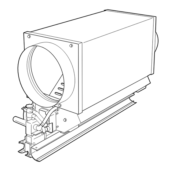
The Moduline air terminal (Fig. 1) is a truly flexible unit
for the control and distribution of conditioned air to the oc-
cupied space. Available in 3 airflow sizes for single or mul-
tiple terminal installation, it is adaptable to a variety of
Fig. 1 — Moduline Air Terminal
Form 37HS-1XA
Pg 1
37HS
Page
6-91
Replaces: New
Advertisement
Table of Contents

Related Manuals for Carrier MODULINE 37HS


Summary of Contents for Carrier MODULINE 37HS
-
Page 1: Application Data
CONTENTS INTRODUCTION ......1-2 BUILDING LOAD CALCULATION ..2-23 Cooling . -
Page 2: Building Load Calculation
Product Integrated Controls (PIC) can be found in a separate publication. (Moduline units with PIC controls can be con- trolled as part of the Carrier Comfort Network [CCN] sys- tem.) Sound power levels and sound application data are found in the 37HS Sound Application Data book. Specific mount-... - Page 3 DESIRED ROOM TEMPERATURE These minimums are based on using the Carrier Modu- line diffuser, which has very high performance; competitive diffusers require a higher cfm/sq ft. The outside air cfm requirement at maximum design con- ditions may be determined by local building code.
- Page 4 The same supply air temperature must be used for the zone load and block load estimates. Load Calculating Methods — The cooling load estimates can be made very accurately and quickly using the Carrier E20-II Block Load program. Because of the computer’s speed, it is not necessary to compromise the design procedure to obtain the most accu- rate result.
-
Page 20: Heating
Moduline Selection (Analysis of Data) — The printout shown below presents an analysis of the preceding data. Heating — Heat must be provided in a building to offset losses through the perimeter walls, windows, and roof. In the interior spaces the heat gain from lights and people will in many cases be enough to cause a cooling load even in winter. - Page 21 Fig. 5 — Separate Duct Heating System Fig. 6 — 35BD Heating Slot Boot Diffuser Performance Heating — Downblow Slot NOMINAL LENGTH (ft) Placement TYPE (in.) DIFFUSER Heating Slot 20-70 25-120 Boot Diffuser NOTES: 1. Minimum and maximum show distance diffuser should be lo- cated from perimeter wall in inches.
- Page 22 Changeover Moduline Heating/Cooling — Both hot air and cold air distribution are possible with a Moduline system. The Moduline unit uses a director diffuser which, sensing the duct temperature of the supply air, directs the air towards or away from the perimeter wall. (Fig. 7.) HEATING With hot air in the duct, all discharge air is directed towards the perimeter wall to offset the transmission.
-
Page 23: Introduction
Additional Guidelines for Heating — In addition to down- blow slot boot diffusers and Moduline director diffusers, round nozzles spaced along the perimeter wall will also provide satisfactory overhead heating distribution. Some guidance for outlet use are shown in Tables 1 and 2. Moduline heating and cooling is less flexible than sepa- rate duct system heating with Moduline cooling because: •... -
Page 24: Per Terminal
Fig. 9 — Single Moduline Unit Connected to Supply Duct Fig. 10 — Moduline Units in Air Series Fig. 11 — Master Unit and Slave Units CONTROL END — The control end of a Moduline unit is the end containing a control block at the end plate of the valve section of the unit. -
Page 25: Step 2 — Lay Out Terminals
As a result, slightly higher maximum cfm per unit is al- lowed as compared to interior zones or the north perimeter, which have relatively constant loads. The maximum cfm per unit also is affected by the desired sound level in the room and the type of use of the space. For example, an executive office uses low sound levels but the furnishings generally absorb more sound so the al- lowable cfm/unit is only slightly lower than other types of... - Page 26 EVALUATE THE THROW OF MODULINE UNITS IN POSSIBLE LOCATIONS — Check minimum throw for 2-way blow diffuser near walls and all one-way blow diffusers. Exceeding maximum throw is almost never a problem. A 2-way blow unit covers 50 ft at nominal cfm. In perimeter rooms, if 2-way blow units are off center, favor the exterior wall if possible.
-
Page 27: And Run-Out Duct
STAGGER SPACING — A frequently used layout method is to stagger the units. This arrangement gives good cover- age, solves the problem of drafts when units blow at each other, and is low cost. It also gives good flexibility for future partition changes. - Page 28 Fig. 19 — Run-Out Duct for Single Moduline Unit Fig. 20 — Run-Out Duct for Moduline Units in Air Series...
- Page 29 Table 6 — 37HS1 Units in Air Series...
- Page 30 Table 6 — 37HS1 Units in Air Series (cont)
- Page 31 Table 7 — 37HS2 Units in Air Series...
- Page 32 Table 7 — 37HS2 Units in Air Series (cont) Table 8 — 37HS4 Units in Air Series...
- Page 33 Table 8 — 37HS4 Units in Air Series (cont)
- Page 34 Table 9 — Maximum Cfm Through the Inlet Collar of a Single Unit or of Units in Air Series INLET PLENUM COLLAR MODEL SIZE DIAM (in.) (in.) 5 x 7 7 x 7 37HS1 9 x 9 11 x 11 7 x 7 37HS2 9 x 9...
- Page 35 Fig. 22 — Air Series of Units of the Same Size and Capacity FLEX DUCT IN AIR SERIES — Flexible duct is often used in air series to connect Moduline units. In calculating pres- sure requirements for units in air series, use the following guidelines: 1.
- Page 36 Table 10 — Minimum Static Pressure at Control (Master) Unit — Units with System-Powered Controls and Standard Diffusers 37HS1 PLENUM SIZE (in.) AIRFLOW 7 x 7 (Cfm) 5 x 7 9 x 9 11 x 11 Minimum Static Pressure (in. wg) 0.75 0.75 0.75...
-
Page 37: Step 4 — Determine Controller Location
Fig. 25 — Flexible Duct Used with 90-Degree Bend Step 4 — Determine Controller Location — final step in the terminal selection and layout process is to decide where the controllers will be placed. The temperature control zones in the building will be de- termined by the final partition layout. - Page 38 4. The controller for units in an air series should be located as shown in Fig. 28. 5. Volume controllers for units in an air series must be con- nected from master to slave units in the same air series; they must not be connected to units in a different air series from that of the master unit.
- Page 39 EXAMPLES OF GUIDELINE USE — Figure 29 shows an incorrect application. Figure 30 shows the corrected layout. An incorrect application: 1. Room A & B units are on the same controller but on different duct air series. 2. Room B calls for half the cfm as in units in room A — not feasible because there is only one controller.
- Page 40 The corrected layout: 1. Room A has its own controller. 2. Room B has its own controller. 3. Room C has a correct air series for one control. 4. Room D has the controller in the proper location. Fig. 30 — Corrected Layout Fig.
-
Page 41: Final Layout
The valve opening varies with the pressure of the bellows and the pressure of the plenum. Figure 33 shows the internal components of the Moduline unit. Figure 34 shows the comparison of operating character- istics between Carrier’s new Moduline unit (the 37HS) and the previous design. - Page 42 UNIT SHUTOFF — BELLOWS FULLY INFLATED UNIT MODULATING — BELLOWS PARTIALLY INFLATED UNIT FULL CAPACITY — BELLOWS DEFLATED Fig. 32 — Bellows and Unit Air Valve Arrangement...
- Page 43 HIGH AND LOW PRESSURE — As primary air flows from the unit plenum to the unit air valve and from there to the conditioned space, it passes through a slotted plate called the distribution baffle. The resistance of the baffle tends to ‘‘even out’’...
-
Page 44: Control Applications
Fig. 35 — High and Low Pressure Pick-Up Tubes BELLOWS PRESSURE — As the airflow through the unit changes, the high and low pressures vary proportionately. Comparing these 2 pressures, the unit volume controller pro- vides a bellows pressure which in turn inflates the unit air valve. - Page 45 Fig. 36 — 37HS Control Components Fig. 37 — Basic 37HS Control Operation...
- Page 46 Fig. 38 — 37HS Control Filter/Manifold Fig. 39 — 37HS Airflow Volume Controller Fig. 40 — Unit-Mounted (Diffuser) Thermostat Both CV and VAV control packages include a plastic baffle which is installed over the vertical leg of the center diffuser and blocks the unused portion of the diffuser slots.
- Page 47 SYSTEM-POWERED APPLICATIONS Constant Volume (CV) Cooling — (Function No. 1.) This is the most basic operating configuration. The control arrange- ment consists of the volume controller and the filter. The unit maintains a steady flow of primary air at the quantity set on the volume controller over a range of supply pressures.
- Page 48 VAV Heating and Cooling With Changeover — (Function 5.) A VAV control arrangement for cooling/heating includes a wall-mounted cooling/heating thermostat and provision to change the thermostat from cooling to heating configuration and back again. Figure 46 shows the control arrangement with Moduline control for heating and cooling.
- Page 49 VAV Cooling With Electric Heat Interlock — (Function 8.) In cases where VAV cooling terminals are used in conjunc- tion with a separate heating system, such as perimeter heat- ing, it is necessary to prevent the heating equipment from turning on before the cooling system turns off. The addition of a differential pressure switch to the unit controls makes this possible.
-
Page 50: Control Packages
NOTE: The following applications require the control pack- ages shown for Function 10, plus field-supplied thermostats as described below. Night Set Back Heating — In the interest of energy conser- vation, it may be desirable to raise a system’s cooling set point during unoccupied time periods, whether they occur at night or on weekends, holidays or other occasions. - Page 51 FUNCTION MODEL SYSTEM POWERED 37HS1 37HS2 CONSTANT VOLUME COOLING 37HS4 SYSTEM POWERED 37HS1 37HS2 VARIABLE VOLUME COOLING 37HS4 DIFFUSER THERMOSTAT SYSTEM POWERED 37HS1 VARIABLE VOLUME COOLING 37HS2 WALL THERMOSTAT 37HS4 Table 15 — 37HS Control Combinations CONTROL PACKAGES REQUIRED 37HS900003 37HS900003 37HS900003 37HS900001...
- Page 52 Table 15 — 37HS Control Combinations (cont) FUNCTION MODEL SYSTEM POWERED 37HS1 VARIABLE VOLUME COOLING SYSTEM POWERED 37HS2 WARM-UP WALL THERMOSTAT* 37HS4 SYSTEM POWERED 37HS1 VARIABLE VOLUME HEATING & COOLING SYSTEM POWERED 37HS2 CHANGEOVER WALL THERMOSTAT 37HS4 SYSTEM POWERED 37HS1 VARIABLE VOLUME COOLING ELECTRIC WARM-UP...
- Page 53 Table 15 — 37HS Control Combinations (cont) FUNCTION MODEL SYSTEM POWERED 37HS1 VARIABLE VOLUME HEATING & COOLING ELECTRIC CHANGEOVER 37HS2 WALL THERMOSTAT 37HS4 SYSTEM POWERED 37HS1 VARIABLE VOLUME COOLING 37HS2 DIFFUSER THERMOSTAT** 37HS4 ELECTRIC INTERLOCK TO FAN COIL OR BASEBOARD HEATING SYSTEM POWERED 37HS1 VARIABLE VOLUME...
- Page 54 Table 15 — 37HS Control Combinations (cont) FUNCTION MODEL SYSTEM POWERED VARIABLE VOLUME COOLING 37HS1 PNEUMATIC PILOT VALVE FOR HEATING/COOLING SEQUENCE PNEUMATIC WALL THERMOSTAT†† 37HS2 37HS4 SYSTEM POWERED 37HS1 VARIABLE VOLUME COOLING WALL THERMOSTAT 37HS2 PNEUMATIC WARM-UP/FIRE SWITCH 37HS4 SYSTEM POWERED 37HS1 VARIABLE VOLUME COOLING...
-
Page 55: System-Powered Controls
CONTROL OPERATING SEQUENCES System-Powered Controls CV COOLING — See Fig. 54. Air from above the distri- bution baffle (high pressure) enters the filter through the up- per port of the control block, while the lower port receives air from below the baffle (low pressure). These air streams pass through separate filter chambers where particulate con- taminants are removed. - Page 56 VAV COOLING — In VAV operation, the filter and volume controller perform the same functions as in CV operation. The unit-mounted thermostat modifies control operation as described below. Refer to Fig. 55. The air enters the low pressure chamber of the volume controller through a fixed orifice. The low pres- sure chamber is connected through a stub fitting and tube to the unit-mounted thermostat.
- Page 57 Fig. 56 — Variable Volume Controls — Minimum Flow: Thermostat Partially Open, Controller Partially Open, Unit Delivering Minimum Flow Fig. 57 — Variable Volume Controls — Full Cooling, Thermostat Closed, Controller Bleeding, Unit Supplying Air...
- Page 58 Fig. 58 — Variable Volume Controls — Thermostat Open, VAV COOLING WITH WARM-UP — Including the warm- fup switch in the volume controller/thermostat circuit al- lows the unit to deliver air when there is warm air in the duct system, even though the cooling thermostat is satisfied by cool space temperature.
- Page 59 Fig. 59 — Cooling with Warm-Up — Morning, Hot Air in Duct, Warm-Up Switch Closed, Controller Bleeding, Unit Heating Fig. 60 — Cooling with Warm-Up — Nighttime Condition, Room Cool, Thermostat Open, Bleeding, Warm-Up Open, Controller Shut Off, Unit Shut Off...
- Page 60 Fig. 61 — Location of CV Unit for Warm-Up Application VAV HEATING AND COOLING WITH SYSTEM- POWERED CHANGEOVER — This application uses a CV control package along with a wall-mounted thermostat pack- age (cooling/heating) and a system-powered changeover con- trol package. The cooling thermostat is direct acting (DA) while the heating thermostat is reverse acting (RA).
- Page 61 Fig. 62 — Heating/Cooling Unit — Cooling, Cold Air in Duct, Changeover in Cooling, Thermostat Open, Controller Shut Off, Unit Shut Off Fig. 63 — Heating/Cooling Unit — Heating, Hot Air in Duct, Changeover in Heating, Thermostat Open, Controller Shut Off, Unit Shut Off...
- Page 62 Fig. 64 — Heating/Cooling Unit — Cooling, Cold Air in Duct, Changeover in Cooling, Thermostat Closed, Controller Bleeding, Unit Cooling Fig. 65 — Heating/Cooling Unit — Heating, Hot Air in Duct, Changeover in Heating, Thermostat Closed, Controller Bleeding, Unit Heating...
- Page 63 VAV HEATING — It is suggested that the following section be reviewed before reading this section: VAV Cooling, page 56. Combining a diffuser-mounted constant volume control pack- age with a wall-mounted thermostat package (heating only) allows the use of Moduline units in VAV heating applications.
-
Page 64: Electric Interface
Fig. 67 — Variable Volume Controls — Minimum Flow: Thermostat Partially Open, Controller Partially Open, Unit Delivering Minimum Flow System-Powered Controls with Electric Interface VAV COOLING WITH ELECTRIC WARM-UP — Another approach to warm-up is the addition of an electric warm-up valve;... - Page 65 Fig. 68 — Cooling with Warm-Up — Morning, Hot Air in Duct, Warm-Up Switch Closed, Controller Bleeding, Unit Heating Fig. 69 — Cooling with Warm-Up — Nighttime Condition, Room Cool, Thermostat Open, Bleeding, Warm-Up Open, Controller Shut Off, Unit Shut Off...
- Page 66 VAV HEATING AND COOLING WITH ELECTRIC CHANGEOVER — This application uses a CV control pack- age along with a wall-mounted thermostat package (cooling/ heating) and an electric changeover package. The change- over valve permits control of the unit to be switched between the cooling and heating sides of a cooling/heating thermo- stat.
- Page 67 Fig. 71 — Heating/Cooling Unit — Heating, Hot Air in Duct, Electric Changeover in Heating, Thermostat Open, Controller Shut Off, Unit Shut Off Fig. 72 — Heating/Cooling Unit — Cooling, Cold Air in Duct, Electric Changeover in Cooling, Thermostat Closed, Controller Bleeding, Unit Cooling...
- Page 68 Fig. 73 — Heating/Cooling Unit — Heating, Hot Air in Duct, Electric Changeover in Heating, Thermostat Closed, Controller Bleeding, Unit Heating VAV COOLING WITH ELECTRIC HEAT INTERLOCK — A conditioned space may contain a Moduline system for cool- ing and a separate heating system such as baseboard electric or hot water or an overhead fan coil.
-
Page 69: Pneumatic Interface
System-Powered Controls with Pneumatic Interface PNEUMATIC SEQUENCED HEATING/COOLING (HOT WATER) — By using a 20 psi pneumatic source, one ther- mostat can control both heating and Moduline cooling in the conditioned space. The pneumatic circuit is interfaced with the system-powered circuit by use of a pilot valve. In cool- ing, the Moduline airflow is controlled by the duct-powered volume controller just as in all system-powered control. - Page 70 VAV COOLING WITH PNEUMATIC WARM-UP OR FIRE SAFETY SWITCH — Through the use of a specific pneu- matic switch, the functions of pneumatic warm-up and fire safety can be added to Moduline installations. Pneumatic warm-up offers an opportunity to open all Modu- line units in an area to allow immediate hot air distribution prior to the building occupancy.
-
Page 71: Airflow Adjustment
Fig. 82A — NO Configuration for Fire Safety Fig. 82B — NC Configuration for Fire Safety Fig. 83 — Fire Safety Switch Floor Layout AIRFLOW ADJUSTMENT Each 37HS volume controller is equipped with a maxi- mum cfm lever for setting the required unit airflow in the field. -
Page 72: Variation In Maximum Airflow
MAXIMUM CFM LEVER Fig. 84 — Minimum and Maximum Airflow Adjustments, 37HS Controller Variation in Maximum Airflow — the Terminal Selection and Layout section, Moduline units in air series can be controlled individually with a volume controller at each unit, or with a master/slave combination, where one controller is used with multiple units. -
Page 73: Air Distribution
AIR DISTRIBUTION Linear slot diffusers are an integral part of the Moduline unit. They provide excellent air distribution for the condi- tioned space. The diffuser configuration is designed to in- duce room air, creating continuous air motion for occupants of the room and reasonably consistent temperatures from floor to ceiling. - Page 74 37HS — 2-WAY BLOW 37HS2 — ONE-WAY BLOW Fig. 86 — Typical Room Air Distribution Pattern...
- Page 75 Fig. 87 — Slot Openings in Standard and Optional Diffusers...
- Page 76 UNIT DESIGNATION CONFIGURATION MODEL 37HS1 DIRECTOR DIFFUSER REMOVABLE DIFFUSER REMOVABLE DIFFUSER Table 18 — Standard Diffusers for 37HS1 FLOW 2-Way One-Way Two-Way One-Way 2-Way 2-Way LENGTH MATERIAL MODE (in.) 22.92 Tegular T-Bar 46.92 Alum Cooling Continuous T-Bar 23.38 Narrow T-Bar 47.38 1174 mm 1200 mm...
- Page 77 UNIT DESIGNATION CONFIGURATION MODEL 37HS2 DIRECTOR DIFFUSER REMOVABLE DIFFUSER REMOVABLE DIFFUSER Table 19 — Standard Diffusers for 37HS2 FLOW 2-Way One-Way 2-Way One-Way 2-Way 2-Way LENGTH MATERIAL MODE (in.) 46.92 Tegular T-Bar 58.92 Alum Cooling Continuous T-Bar 47.38 Narrow T-Bar 59.38 1174 mm 1200 mm...
- Page 78 UNIT DESIGNATION CONFIGURATION MODEL 37HS4 DIRECTOR DIFFUSER REMOVABLE DIFFUSER REMOVABLE DIFFUSER Table 20 — Standard Diffusers for 37HS4 FLOW 2-Way One-Way 2-Way One-Way 2-Way 2-Way LENGTH MATERIAL MODE (in.) 46.92 Tegular T-Bar 58.92 Alum Cooling Continuous T-Bar 47.38 Narrow T-Bar 59.38 1174 mm 1200 mm...
- Page 79 UNIT DESIGNATION CONFIGURATION MODEL 37HS1 Table 21 — Optional Diffusers for 37HS1 FLOW 2-Way One-Way 2-Way One-Way; 2-Slot 2-Way One-Way; 3-Slot LENGTH MATERIAL MODE (in.) 22.92 Tegular T-Bar 46.92 Alum Cooling Continuous T-Bar 23.38 Narrow T-Bar 47.38 1174 mm 1200 mm 22.92 Tegular T-Bar 46.92...
- Page 80 UNIT DESIGNATION CONFIGURATION MODEL 37HS2 DIRECTOR DIFFUSER DIRECTOR DIFFUSER Table 22 — Optional Diffusers for 37HS2 FLOW 2-Way One-Way 2-Way One-Way; 2-Slot 2-Way One-Way; 3-Slot LENGTH MATERIAL MODE (in.) 46.92 Tegular T-Bar 58.92 Alum Cooling Continuous T-Bar 47.38 Narrow T-Bar 59.38 1174 mm 1200 mm...
- Page 81 UNIT DESIGNATION MODEL 37HS4 DIRECTOR DIFFUSER DIRECTOR DIFFUSER Table 23 — Optional Diffusers for 37HS4 CONFIGURATION FLOW 2-Way One-Way 2-Way One-Way 2-Way LENGTH CEILING MATERIAL MODE (in.) TYPE T-Bar 46.92 Tegular T-Bar 58.92 Alum Cooling Continuous T-Bar 47.38 Narrow T-Bar 59.38 1174 mm Metric...
-
Page 82: Throw For Standard Diffusers
Throw for Standard Diffusers — provide the suggested minimum and maximum coverages the Moduline® air terminals can handle in a typical instal- lation while maintaining the desired room conditions. Table 24 — Air Throw Data — 1-Way and 2-Way Blow, 2-Slot Diffusers OPTIMUM AIR THROW (ft) 37HS1 UNIT AIRFLOW... - Page 84 Copyright 1991 Carrier Corporation Manufacturer reserves the right to discontinue, or change at any time, specifications or designs without notice and without incurring obligations. Book 3 PC 201 Catalog No. 513-741 Printed in U.S.A. Form 37HS-1XA Pg 84 6-91 Replaces: New...
Need help?
Do you have a question about the MODULINE 37HS and is the answer not in the manual?
Questions and answers