Carrier Moduline 37HS Series Installation, Start-Up And Service Instructions Manual
Air terminals
Hide thumbs
Also See for Moduline 37HS Series:
- Application data (85 pages) ,
- Installation instructions and parts list (2 pages) ,
- Installation instructions manual (32 pages)
Table of Contents
Advertisement
Quick Links
Installation, Start-Up and Service Instructions
CONTENTS
INTRODUCTION . . . . . . . . . . . . . . . . . . . . . . . . . . . 1
INSTALLATION . . . . . . . . . . . . . . . . . . . . . . . . . . . . 1
Installation Precautions . . . . . . . . . . . . . . . . . . . . 3
General . . . . . . . . . . . . . . . . . . . . . . . . . . . . . . . . . . . 3
Unit/Ceiling Coordination . . . . . . . . . . . . . . . . . . . 8
Unit-to-Unit Connections . . . . . . . . . . . . . . . . . . . 8
Unit Suspension . . . . . . . . . . . . . . . . . . . . . . . . . . 8
Unit Installation . . . . . . . . . . . . . . . . . . . . . . . . . . . 8
Controls . . . . . . . . . . . . . . . . . . . . . . . . . . . . . . . . . 15
• GENERAL
• AIRFLOW ADJUSTMENT
START-UP . . . . . . . . . . . . . . . . . . . . . . . . . . . . . . . 28
Principles of Operation . . . . . . . . . . . . . . . . . . . . 28
Preliminary System Check . . . . . . . . . . . . . . . . . 29
Initial Start-Up . . . . . . . . . . . . . . . . . . . . . . . . . . . 29
SERVICE . . . . . . . . . . . . . . . . . . . . . . . . . . . . . . . . 29
Gaining Access to Control Area . . . . . . . . . . . . . 29
TROUBLESHOOTING . . . . . . . . . . . . . . . . . . . . . . 29
General . . . . . . . . . . . . . . . . . . . . . . . . . . . . . . . . . 29
Checking for Obstruction . . . . . . . . . . . . . . . . . . 29
Checking for Leaks . . . . . . . . . . . . . . . . . . . . . . 29
To Check Duct Pressure . . . . . . . . . . . . . . . . . . . 30
INTRODUCTION
Moduline® units are integral diffuser air terminals. They
are available with various control devices for constant vol-
ume and variable volume heating and cooling applications.
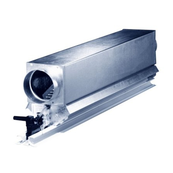
All units consist of a plenum, valve assembly and dif-
fuser. A typical unit is shown in Fig. 1. The plenum is ther-
mally and acoustically insulated and contains a distribution
baffle to provide well-distributed flow to the valve assembly.
Fig. 2 shows a cross section of a typical 37HS unit.
The valve assembly includes the bellows, which is in-
flated in proportion to the duct pressure to regulate airflow
to the space. The bellows is constructed of durable polyure-
thane. The assembly is connected at either end to
control tubing.
The diffuser assembly is available in a 2-slot, one- or 2-way
blow configuration. A 3-slot director diffuser is available for
use in cooling/heating applications.
The standard diffuser assembly is not removable. Control
access is made through a ceiling opening (e.g., a removable
ceiling tile) or nearby light fixture. The 37HS Moduline ter-
minal is also available with a removable diffuser for instal-
lation in nonaccessible ceilings.
Manufacturer reserves the right to discontinue, or change at any time, specifications or designs without notice and without incurring obligations.
Book 3
PC 201
Tab
6a
Page
1
⁄
-in. OD
4
Catalog No. 533-710
Printed in U.S.A.
Moduline® Air Terminals
Fig. 1 - Typical 37HS Moduline Air Terminal
Fig. 2 - Typical 37HS Moduline
Unit Cross Section
INSTALLATION
Unit Identification -
carton. Compare unit nameplate with model number nomen-
clature shown in Fig. 3 to be sure correct unit has been
received.
Form 37HS-1SI
37HS
PLENUM
VALVE
ASSEMBLY
CENTER
DIFFUSER
Units are factory-shipped one per
Pg 1
3-91
Replaces: New
Advertisement
Table of Contents

Related Manuals for Carrier Moduline 37HS Series


Summary of Contents for Carrier Moduline 37HS Series
-
Page 1: Table Of Contents
37HS Moduline® Air Terminals Installation, Start-Up and Service Instructions CONTENTS PLENUM Page INTRODUCTION ......1 INSTALLATION . - Page 2 DIGIT 1 2 3 4 6 7 8 9 10 11 12 13 MODEL NO. 3 7 H S 8 6 2 L N C 37HS — System-Powered Terminal Unit Unit Size — Airflow (Nominal Cfm) Packaging 1 — 100 C —...
-
Page 3: Installation Precautions
Installation Precautions — General — When installing units, make The 37HS Moduline® units are designed for sure that construction debris does not enter unit or duct- installation in standard, narrow and tegular T-bar ceilings, work. Do not remove protective tape from diffuser until in- and for continuous run, concealed spine or plaster ceilings. - Page 4 STANDARD DIFFUSER LENGTHS AVAILABLE (in inches) NOTE: Dimensions are in inches. PLENUM SIZE (sq) 46.92 47.00 47.38 48.00 58.92 59.00 59.38 60.00 1.25 1.25 1.25 1.25 7.25 7.25 7.25 7.25 — — — 39.25 41.25 — 41.25 — 41.25 — 41.25 —...
- Page 5 EXTRUDED ALUMINUM EXTRUDED ALUMINUM EXTRUDED ALUMINUM 2-WAY BLOW ONE-WAY BLOW 3-SLOT Dimensions are in inches. REMOVABLE DIFFUSER (STEEL) REMOVABLE DIFFUSER (ALUMINUM) 37HS1 (100 Cfm) 37HS2 (200 Cfm) CEILING T-BAR STYLE AND WIDTH DIFFUSER LENGTH (in.) CEILING T-BAR STYLE AND WIDTH DIFFUSER LENGTH (in.) 23.00 47.00...
- Page 6 EXTRUDED ALUMINUM EXTRUDED ALUMINUM EXTRUDED ALUMINUM 2-WAY BLOW ONE-WAY BLOW 3-SLOT AVAILABLE LENGTHS (in.) 37HS1 37HS2 37HS4 23.00 47.00 47.00 47.00 47.38 47.38 59.00 59.00 Fig. 9 — Accessory Return-Air Diffusers 37HS1, 2 A (in.) 47.00 48.00 59.00 60.00 37HS4 A (in.) NOTES: 47.00...
- Page 7 Table 1 — Installation Accessories for 37HS Units ADAPTER CAP, Qty 12 END TRIM, Qty 50 Adapter Package No. Used On 37HS1, HS2 Color Package No. For 6-in. round adapter 37AH900102 T-Bar* White 37CM900132 For 8-in. round adapter 37AH900042 2-Slot Tegular†...
-
Page 8: Unit/Ceiling Coordination
Unit/Ceiling Coordination — Unit Installation Set up a ceiling mock-up to familiarize all trades with their functions during installa- T-BAR CEILING tion. Coordinate unit installation with ceiling construction. NOTE: Moduline® systems are normally designed with mul- This is particularly important in custom installations with tiple unit and control arrangements within a single system. - Page 9 WEDGE T-BAR SUPPORT WIRE (MAIN T-BAR MEMBER) WEDGE MOUNT BRACKET Fig. 14 — T-Bar Mounting Details Installation of Return-Air Diffusers and Dummy Diffusers Fig. 16 — Installed Hanger Mounting Brackets — Install one-piece mounting brackets onto diffuser ends using screws provided. See Fig. 15. (For 37HS 3-slot direc- tor diffuser, use 2-piece mounting bracket.) Raise unit to ceil- ing and set in position with the tabs of the mounting bracket placed securely over the T-bar upright.
-
Page 10: Side Diffusers
TEGULAR CEILING — A tegular (recessed T-bar) ceiling The recessed T-bar may be painted (usually black with is constructed the same as a standard T-bar type ceiling, ex- white tiles) to create an interesting grid pattern. The 37HS cept that each lay-in ceiling panel is rabbeted. This means unit center diffuser (when installed on the grid line) may be that the panel is notched to fit over the T-bar. -
Page 11: Nonaccessible Ceilings
NONACCESSIBLE CEILINGS — Nonaccessible ceilings method, shown in Fig. 20, shows 2 Model 37HS Moduline® include plaster and concealed spline ceilings. These appli- air terminals installed. Wire hangers with eyebolts for lev- cations require the 37HS equipped with a removable dif- eling and supporting the terminals are shown at the plenum fuser assembly. - Page 12 Section B-B is a view of the plaster frame resting on the PLASTER CEILING OPENINGS diffuser end trim strip. The installed Moduline® air terminal DIMENSIONS (in.) provides an excellent, secure installation. UNIT DIFFUSER The 37HS Moduline matching dummy and return-air dif- 37HS1 2-Way fusers may also be independently suspended when applied...
- Page 13 Fig. 22 — 37HS Moduline® Units Installed in a Plaster Ceiling Fig. 23A — Typical Concealed Spline Ceiling Using 37HS Air Terminals (Details)
- Page 14 Fig. 23B — Typical Concealed Spline Ceiling Using 37HS Air Terminals...
-
Page 15: Controls
Controls GENERAL — System powered or duct pressure controls used with Moduline® terminals provide both volume and tem- perature control without the need for separate pneumatic or electric energy. The plenum pressure supplies the power re- AIR FILTER quired by the control devices. The standard 37HS control arrangement is shown in Fig. - Page 16 SINGLE MASTER UNIT INSTALLATION MASTER UNIT WITH ONE SLAVE MASTER UNIT WITH 3 SLAVES Fig. 26 — Control Arrangements — Master Units with Slaves...
-
Page 17: Operating Sequences
OPERATING SEQUENCES — System powered control for A minimum airflow can be set on the volume controller to the Moduline® terminal is shown schematically in Fig. 27. prevent the unit from closing completely. The minimum air- flow adjustment restricts the volume controller seat from clos- System Powered Cooling—... - Page 18 Table 2 — 37HS Control Combinations CONTROL FUNCTION MODEL PACKAGES CONNECTION ARRANGEMENT REQUIRED SYSTEM POWERED 37HS1 37HS900003 37HS2 37HS900003 CONSTANT VOLUME COOLING 37HS4 37HS900003 SYSTEM POWERED 37HS1 37HS900001 37HS2 37HS900002 VARIABLE VOLUME COOLING 37HS4 37HS900004 DIFFUSER THERMOSTAT SYSTEM POWERED 37HS900003 37HS1 37CM901012 VARIABLE VOLUME...
- Page 19 Table 2 — 37HS Control Combinations (cont) CONTROL FUNCTION MODEL PACKAGES CONNECTION ARRANGEMENT REQUIRED SYSTEM POWERED 37HS900003 37HS1 37CM900152 VARIABLE VOLUME 37CM901012 COOLING 37HS900003 SYSTEM POWERED 37HS2 37CM900152 WARM-UP 37CM901012 WALL THERMOSTAT* 37HS900003 37HS4 37CM900152 37CM901012 SYSTEM POWERED 37HS900003 37HS1 37CM900192 VARIABLE VOLUME 37CM901992...
- Page 20 Table 2 — 37HS Control Combinations (cont) CONTROL FUNCTION MODEL PACKAGES CONNECTION ARRANGEMENT REQUIRED SYSTEM POWERED 37HS900003 37HS1 37CM900792† VARIABLE VOLUME 37CM901992 HEATING & COOLING 37HS900003 ELECTRIC CHANGEOVER 37HS2 37CM900792† 37CM901992 WALL THERMOSTAT 37HS900003 37HS4 37CM900792† 37CM901992 SYSTEM POWERED 37HS900001 37HS1 37CM900922 VARIABLE VOLUME...
- Page 21 Table 2 — 37HS Control Combinations (cont) CONTROL FUNCTION MODEL PACKAGES CONNECTION ARRANGEMENT REQUIRED SYSTEM POWERED 37HS900003 37CM900972 (NO) VARIABLE VOLUME with COOLING 37HS1 37HS900007 (DA) PNEUMATIC 37CM900982 (NC) PILOT VALVE FOR with HEATING/COOLING 37HS900008 (RA) SEQUENCE 37HS900003 PNEUMATIC WALL 37CM900972 (NO) THERMOSTAT††...
- Page 22 CONTROL INSTALLATION — Controls may be installed in the unit before or after the unit is hung or placed in the ceiling grid. However, if warm-up switches or changeover valves are used, the controls should be installed before the unit is placed in the ceiling structure. Refer to Table 3 for control packages and accessory identification.
- Page 23 THERMOSTAT PORT SHIM INDICATOR ADJUSTMENT Fig. 35 — 37HS Control Connections LABEL Fig. 32 — Setting Maximum Volume (37HS Controller) Variable Air Volume Applications 1. Remove the plugs from the high-pressure and low- pressure ports located at the control block of the unit. 2.
-
Page 24: Control Installation
37HS1: Because of the limited space on the 23-in. 37HS1 unit, the 37HS1 VAV control has a different method of assembly. a. Remove cap from thermostat port of volume control- ler. See Fig. 32. Pull shim down until released from AIR FILTER thermostat port and then pull shim out from volume controller body. - Page 25 Table 3 — Control Identification CONTROL PACKAGE, VARIABLE VOLUME, QTY 1 CONTROL PACKAGE, CONSTANT VOLUME, QTY 1 USED ON PACKAGE NO. USED ON PACKAGE NO. 37HS1 37HS900001 37HS1 37HS900003 37HS2 37HS900002 37HS2 37HS900003 37HS4 37HS900004 37HS4 37HS900003 ADAPTER FILTER/ TUBE MANIFOLD FILTER/MANIFOLD DIFFUSER...
- Page 26 Table 3 — Control Identification (cont) ELECTRIC INTERLOCK PNEUMATIC WALL THERMOSTAT Used On Package No. Used On Package No. 37HS1 37CM900922 37HS1 37HS900007 (DA) 37HS2 37CM900922 37HS2 37HS4 37CM900922 37HS4 37HS900008 (RA) PNEUMATIC PILOT VALVE PNEUMATIC WARM-UP/FIRE SWITCH FOR HEATING/COOLING SEQUENCE Used On Package No.
- Page 27 OPEN MINIMUM CFM STAR WHEEL MAXIMUM CFM LEVER VOLUME CONTROLLER Fig. 39 — Minimum and Maximum Airflow Adjustments, 37HS Controller To set maximum cfm with zero minimum cfm: To set maximum and minimum cfm: 1. Set diffuser or wall thermostat for maximum cooling. 1.
-
Page 28: Functional Checkout
Table 7 — Minimum Static Pressure at Control FUNCTIONAL CHECKOUT — With building temperature within Moduline® thermostat set point limits (70 to 80 F), (Master) Unit — Units with System-Powered Controls and Standard Diffusers VAV supply air at design temperature and VAV supply pres- sure between 0.75 and 3.0 in. -
Page 29: Preliminary System Check
VARIABLE AIR VOLUME OPERATION — The constant Before performing any check, be sure that plenum pres- volume control becomes variable volume control with the sure is a minimum of 0.75 in. wg and that supply-air tem- addition of a thermostat. The thermostat enables the control perature is 50 to 60 F and room temperature is 70 to 80 F. -
Page 30: To Check Duct Pressure
To Check Duct Pressure — To check duct pressure METAL "T" on master unit, remove the volume controller from the filter and connect a Magnehelic gage tube to the filter high- pressure port (shown on Fig. 31). After checking, replace vol- ume controller. - Page 31 TROUBLESHOOTING CHART SYMPTOM POSSIBLE CAUSE CORRECTIVE PROCEDURE ROOM TOO COLD Thermostat Setting Check thermostat setting — move thermostat lever slightly Incorrect toward red area. If unit shuts off, leave in this (or in an intermediate) position. See Fig. 40. Volume Controller Check actual volume controller setting vs design cfm —...
- Page 32 Copyright 1991 Carrier Corporation Manufacturer reserves the right to discontinue, or change at any time, specifications or designs without notice and without incurring obligations. Book 3 PC 201 Catalog No. 533-710 Printed in U.S.A. Form 37HS-1SI Pg 32 3-91 Replaces: New...
Need help?
Do you have a question about the Moduline 37HS Series and is the answer not in the manual?
Questions and answers