Table of Contents
Advertisement
Quick Links
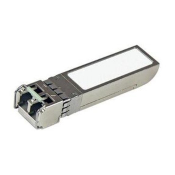
RoHS Compliant 8.5Gb/s Short Wavelength SFP+ Transceiver
Description
The LCP-8500A4EDR is hot pluggable 3.3V
Small-Form-Factor transceiver modules designed
expressly
for
high-speed
applications that require rates of up to 8.5Gb/s.
It is compliant with SFP+ MSA, SFF-8431
specification and Fiber Channel FC-PI-4, as well as
MSA SFF-8472.
The LCP-8500A4EDR transceivers provide with the
LC receptacle that is compatible with the industry
TM
standard LC
connector. The transceiver is also
compatible with industry standard RFT connector
and cage.
The post-amplifier of the LCP-8500A4EDR also
includes a LOS (Loss Of Signal) circuit that
provides a TTL logic-high output when an
unusable optical signal level is detected.
The LCP-8500A4EDR transceiver is a Class 1
eye safety product. The optical power levels,
under normal operation, are at eye safe level.
DELTA ELECTRONICS, INC.
FEATURES
Compliant with SFP+ MSA, SFF-8431
specification and Fiber Channel FC-PI-4
Compliant with SFF-8472 MSA
850nm VCSEL laser
Built-in digital diagnostic monitoring function
Backward compatible to 2G/4G Fiber Channel
Duplex LC connector
Power consumption <1W
Laser Class 1 Product which comply with the
requirements of IEC 60825-1 and IEC 60825-2
Applications
High-speed storage area networks
communication
Computer cluster cross-connect
Custom high-speed data pipes
1
Preliminary
LCP-8500A4EDR
2008/7/16
Rev. 0A
www.deltaww.com
Advertisement
Table of Contents

Related Manuals for Delta Electronics LCP-8500A4EDR


Summary of Contents for Delta Electronics LCP-8500A4EDR
- Page 1 LOS (Loss Of Signal) circuit that provides a TTL logic-high output when an unusable optical signal level is detected. The LCP-8500A4EDR transceiver is a Class 1 eye safety product. The optical power levels, under normal operation, are at eye safe level.
-
Page 2: Absolute Maximum Ratings
These are 20%~80% values. Internally AC coupled, but requires a 100 Ohm differential termination at or internal to Serializer/ Deserializer. VeeT with a >30k ohms resistor in the module. Shall be pulled low to DELTA ELECTRONICS, INC. Symbol Min. Typ. Max. -
Page 3: Optical Characteristics
Distance, shown in the “Link Length” table, are calculated for worst case fiber and transceiver characteristics based on the optical and electrical specifications shown in this document using techniques utilized in IEEE 802.3. In the nominal case, longer distances are achievable. DELTA ELECTRONICS, INC. -1 NRZ, 50/125µm MMF) Symbol Min. - Page 4 Preliminary LCP-8500A4EDR SFP+ Transceiver Electrical Pad Layout Module Electrical Pin Definition 2008/7/16 Rev. 0A www.deltaww.com DELTA ELECTRONICS, INC.
- Page 5 3. This pin is an open collector/drain input pin and shall be pulled up with 4.7k-10k ohms to VccT in the Module. 4. This pin shall be pulled up with 4.7k-10k ohms to Host_Vcc on the host board. DELTA ELECTRONICS, INC. Name/Description Module Transmitter Ground Module Transmitter Fault Transmitter Disable;...
- Page 6 RX_LOS pin is an open drain/collector outpit and must be pulled up to host Vcc with a 4.7k-10k ohms on the host board. RX_LOS assert min and de-assert max are defined in the relevant standard. To avoid spurious transition of RX_LOS a minimum hysteresis of 0.5 dBo is recommended. 2008/7/16 Rev. 0A www.deltaww.com DELTA ELECTRONICS, INC.
- Page 7 Recommend Circuit Schematic Protocol Vcc Tx_Disable Tx_Fault SerDes IC Protocol IC Rx_LOS Receiver Rate Select Transmitter Rate Select PLD / PAL DELTA ELECTRONICS, INC. 3.3V 10uF 0.1uF RES1 VccT 0.1uF Tx_Disable Tx_Fault VeeT RES1 VccR 10uF 0.1uF 100 Ohms* Rx_LOS VeeR 3.3V...
- Page 8 Preliminary LCP-8500A4EDR Package Outline Drawing for Metal Housing with Bail de-latch 2008/7/16 Rev. 0A www.deltaww.com DELTA ELECTRONICS, INC.
- Page 9 Time TX_Disable must be held High to reset TX_Fault. From assertion till stable output. 10) From Occurrence of loss of signal to assertion of LOS. 11) From Occurrence of presence of signal to negation of RX_LOS. DELTA ELECTRONICS, INC. Symbol Min. t_off...
- Page 10 Note: 1) Write the password (11h, 11h, 11h, 11h) on the bytes of 123-126 of address A2h then the address of bytes 128-255 (User Writable) can be read and written. DELTA ELECTRONICS, INC. LCP-8500A4EDR 2 wire address 1010001 X (A2h)
- Page 11 Byte 63: Check sum of bytes 0-62. Byte 68-83: Serial number. Byte 84-91: Date code. Byte 95: Check sum of bytes 64-94. Byte 128 to 255 had been set hex 00. DELTA ELECTRONICS, INC. Address ASCII Note 1 Note 2...
- Page 12 3) P: Operating optical power of transmitter at room temperature. 4) P : Overload optical power of receiver. : Sensitivity optical power of receiver. 5) Byte 95 contains the low order 8bits of sum of bytes 0-94. DELTA ELECTRONICS, INC. Name Value (Dec.) (MAX.)+15 (MIN.) (MAX.)+10...
- Page 13 RX Optical Power Notes: Temperature is measured internal to the transceiver. Voltage is measured internal to the transceiver. DELTA ELECTRONICS, INC. Description Digital state of the Tx disable input pin Read/ Write bit that allow software disable of laser Digital state of the Tx fault output pin Digital state of the LOS output pin.
-
Page 14: Regulatory Compliance
Duplex SC Receptacle IEC 801.2 (#4) Electrostatic Discharge to MIL-STD-883C the Electrical Pins Method 3015.4 EIAJ#1988.3.2B Version 2, Machine model DELTA ELECTRONICS, INC. Reference Qty’ (1) Satisfied with electrical characteristics of product spec. (2) No physical damage Preliminary LCP-8500A4EDR Evaluation 2008/7/16 Rev.
Need help?
Do you have a question about the LCP-8500A4EDR and is the answer not in the manual?
Questions and answers