
Related Manuals for Panasonic Y5B


Summary of Contents for Panasonic Y5B
- Page 1 FPC connector Y5B and Y5BW Operation manual ACCTF15E-3 2015.07 industrial.panasonic.com/ac/e/...
-
Page 2: Table Of Contents
Guide for Getting FPC connector Y5B and Y5BW Contents 01.Introduction ..................... 2 02.Precautions for product design ............... 3 03.Board arrangement and precautions for using a fold and cut board ..4 04.Precautions for FPC insertion and removal ..........5 05.Handling methods and precautions ............7 06.Precautions for board/metalmasking/FPC design ......... -
Page 3: Introduction
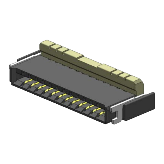
Guide for Getting FPC connector Y5B and Y5BW 01. Introduction Y5B and Y5BW connectors are low-profile, space saving and back-lock type with terminal pitch of 0.5 height of 1.0 mm, and width of 3.20 mm.(3.70mm including lock lever) These connectors are designed for PCB-to-FPC connections of mobile devices and various digital devices. -
Page 4: Precautions For Product Design
Guide for Getting FPC connector Y5B and Y5BW 02. Precautions for product design 02-1. Considerations in mechanical design 1) Position of the connector on a board Rigid boards tend to warp in a direction perpendicular to the rolling direction during the production process. Poor soldering may occur depending on the warping direction. -
Page 5: Board Arrangement And Precautions For Using A Fold And Cut Board
Guide for Getting FPC connector Y5B and Y5BW 03. Board arrangement and precautions for using a fold and cut board (1)Please design and pay attention to the distance from the board edge to the pattern. When cutting the v-cut board, do not give an excessive stress to the connector, which risks damaging the connector. -
Page 6: Precautions For Fpc Insertion And Removal
Guide for Getting FPC connector Y5B and Y5BW 04. Precautions for FPC insertion and removal 1. Do not touch the lever or apply any load to the lever without inserting an FPC. Especially do not close the lever without inserting an FPC. - Page 7 Guide for Getting FPC connector Y5B and Y5BW 6. After FPC insertion, do not apply an excessive load to the lever in the opening direction beyond its open position; otherwise, the lever may be deformed or removed 7. Do not apply an excessive load to the lever in a direction perpendicular to the lever rotation axis or in the lever opening direction;...
-
Page 8: Handling Methods And Precautions
Guide for Getting FPC connector Y5B and Y5BW 05. Handling methods and precautions 1.1 Inserting the FPC 1.1 This product has top and bottom double sided contacts. Pay attention to the face of Designed for top contact:Copper foil is top copper foil, and insert the FPC to the full depth of the connector. - Page 9 Guide for Getting FPC connector Y5B and Y5BW 1.2 How to close the lever 1.2 To close the lever, after inserting the FPC to the full depth of the connector, turn down the lever by pressing the entire lever or both sides of...
- Page 10 Guide for Getting FPC connector Y5B and Y5BW Precautions after FPC insertion * After an FPC is inserted, do not pull the FPC forcefully or do not apply an excessive load. * When using FPC bending, please pay attention to precautions below;...
-
Page 11: Precautions For Board/Metalmasking/Fpc Design
Guide for Getting FPC connector Y5B and Y5BW 06. Precautions for board/metalmasking/FPC design 1) Circuit design (1) Please apply our recommended PC board pattern, window size and thickness of metalmasking, reflow soldering temperature profile, in order to appropriate soldering state. When applying the different dimension of a screen, please contact us as needed. - Page 12 Guide for Getting FPC connector Y5B and Y5BW (5) Design the FPC based on the recommended dimensions to ensure the required connector performance. (6) There are exposed metal parts on the top of connector. Please note that the metal parts do not touch other conductive parts or chassis;...
- Page 13 Guide for Getting FPC connector Y5B and Y5BW 3) FPC Design (1) Design the FPC based on the recommended dimensions to ensure the required connector performance. (2) Make sure that connector positioning and FPC length are appropriate to prevent diagonal insertion of the FPC.
-
Page 14: Precautions For Mounting And Reflow Soldering
Guide for Getting FPC connector Y5B and Y5BW 07. Precautions for mounting and reflow soldering 07-1. Points to consider when selecting a pickup nozzle for mounting Select a pickup nozzle with a suction area that demonstrates a theoretical lifting force... - Page 15 Guide for Getting FPC connector Y5B and Y5BW 07-2. Precautions for reflow soldering 1) Measure the temperature profile at the mounted connector position, and make sure that it conforms to the recommended profile. Recommended reflow temperature profile 2) Depending on reflow condition, poor contact may occur by solder and flux wicking.
- Page 16 Guide for Getting FPC connector Y5B and Y5BW 07-3. Precautions for manual soldering and solder rework The size and thickness of this this connector has been reduced in order to achieve a narrow pitch and save space. Therefore, take a great care when carrying out manual soldering or rework.
- Page 17 Guide for Getting FPC connector Y5B and Y5BW 07-4. Detailed precautions for solder rework (1) Flux-applying tool To prevent solder creeping to a contact section, we recommend the use of a brush pen that can apply an appropriate amount of flux.
- Page 18 Guide for Getting FPC connector Y5B and Y5BW 07-5. Detailed precautions for manual soldering (1) General precautions -When applying flux, apply it thinly on each foot pattern using a brush pen as shown on the previous page. (Place the connector at a predetermined position after applying flux.)
- Page 19 Guide for Getting FPC connector Y5B and Y5BW Amendment history Manual No. Date Changes ACCTF15E-1 Company name and format change August, 2013 ACCTF15E-2 Division name change June, 2015 ACCTF15E-3 p.12 3 (4) added July, 2015 Panasonic Corporation ACCTF15E-3 201507 ©...
- Page 20 ACCTF15E-3 201507...
Need help?
Do you have a question about the Y5B and is the answer not in the manual?
Questions and answers