
Related Manuals for Panasonic A4S


Summary of Contents for Panasonic A4S
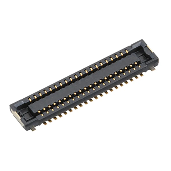
- Page 1 Narrow-pitch Connectors onnector Operation manual ACCTF6E-2 2015.06 industrial.panasonic.com/ac/e/...
-
Page 2: Table Of Contents
Operation manual for Narrow-pitch connectors A4S Contents 01.Introduction ..................... 2 02.Precautions for product design ............... 3 03.Precautions for mounting and reflow soldering ........14 04.Precautions for mating and unmating ........... 20 05.Connectors for inspection and precautions for use ....... 22 Panasonic Corporation ©... -
Page 3: Introduction
Operation manual for Narrow-pitch connectors A4S 01. Introduction Our Advanced series A4S consists of ultra-small connectors with a terminal pitch of 0.4 mm, a stacking height of 0.8mm, and a shorthand width of 2.5 mm. This connector is designed for board-to-FPC connections that require a more space-saving connector than our F4 and F4S Series. -
Page 4: Precautions For Product Design
Operation manual for Narrow-pitch connectors A4S 02. Precautions for product design 02-1. Considerations in mechanical design 1) Position of the connector on a board Rigid boards tend to warp in a direction perpendicular to the rolling direction during the production process. Poor soldering may occur depending on the warping direction. - Page 5 Operation manual for Narrow-pitch connectors A4S 3) Prevention of problems during use (1)The connectors have a simple locking structure, but make sure to consider preventive measures against the detachment of mated connectors during practical use. Cushioning material Casing Reinforcing plate...
- Page 6 Operation manual for Narrow-pitch connectors A4S (3)To facilitate the mating of connectors, we recommend that you pay attention to the following points when designing the motherboard. - Provide a reference mark. - Design a layout that allows easy-checking of the connector mating condition.
- Page 7 Operation manual for Narrow-pitch connectors A4S 02-2. Precautions for board design 1) Circuit design (1)When designing the terminal foot pattern, check the latest specifications and examine the recommended foot pattern and dimensions of the metal mask opening. The current recommendations are indicated on pages...
- Page 8 Operation manual for Narrow-pitch connectors A4S (4)Pay attention to the following point as a pattern peeling preventive measure when removing the connector. - Make the foot pattern length longer than the coverlay opening. In general, at least 0.3 mm. (5)Foot pattern dimensions indicated in the drawings are intended to achieve the minimum area on the premise that the reflow-soldering process is used.
- Page 9 Operation manual for Narrow-pitch connectors A4S 2) FPC board design (1)Positions of connectors on the FPC The FPC board is made by laminating a polyimide layer, copper foil, and adhesive layers. Since each material has slightly different heat-shrinkable properties, warpage may occur typically due the reflow heat in the following cases. This may cause poor soldering.
- Page 10 Operation manual for Narrow-pitch connectors A4S (2)FPC board specifications Control the thicknesses of the coverlay and adhesive to prevent poor soldering. This connector has no stand-off. Therefore, minimize the thickness of the coverlay, etc. so as to prevent the occurrence of poor soldering.
- Page 11 Operation manual for Narrow-pitch connectors A4S 3) Reinforcing plate design We recommend the use of a reinforcing plate with appropriate thickness and rigidity to prevent solder peeling and pattern peeling when unmating the connector, and to guard against board warpage during the reflow process.
- Page 12 Operation manual for Narrow-pitch connectors A4S Metal Mask Design Since this connector is designed with an ultra low-profile, pay attention to the following precautions for reflow soldering. (1)In addition to the amount of applied solder, the reflow-soldering environment and temperature profile affect the finish quality after reflow soldering. Make sure to adjust the amount of solder applied after checking the finish quality in a test run.
- Page 13 Operation manual for Narrow-pitch connectors A4S Recommended specifications for PC-board and metal mask opening area Applicable product: A4S narrow-pitch connector socket Recommended PC-board pattern (Mount-pad layout) Insulation area Recommended metal mask pattern When the metal mask thickness is 120 m...
- Page 14 Operation manual for Narrow-pitch connectors A4S Recommended specifications for PC-board and metal mask opening area Applicable product: A4S narrow-pitch connector header Recommended PC-board pattern (Mount-pad layout) Recommended metal mask pattern When the metal mask thickness is 120 m (Terminal section opening area: 70%)
-
Page 15: Precautions For Mounting And Reflow Soldering
Operation manual for Narrow-pitch connectors A4S 03. Precautions for mounting and reflow soldering 03-1. Points to consider when selecting a pickup nozzle for mounting Select a pickup nozzle with a suction area that demonstrates a theoretical lifting force at least 10 times greater than the connector weight. - Page 16 Operation manual for Narrow-pitch connectors A4S ■ Picking up the header (1)The suction area on the header is 0.7 mm in the shorter direction. If it is difficult to reliably insert the nozzle to the connector bottom face of 0.7 mm widthwise, the header can be picked up by converting the entire top face of the connector as shown below.
- Page 17 Operation manual for Narrow-pitch connectors A4S 03-2. Precautions for reflow soldering (1)Measure the temperature profile at the mounted connector position, and make sure that it conforms to the recommended profile. (2)When the molded part of connector melts or becomes deformed during the reflow process, the heating temperature may be too high, or the connector may be affected by a nearby electronic component with high heat capacity.
- Page 18 Operation manual for Narrow-pitch connectors A4S 03-3. Precautions for manual soldering and solder rework The size of this connector has been reduced in order to achieve a narrow pitch and save space. Therefore, take great care when carrying out manual soldering or rework.
- Page 19 Operation manual for Narrow-pitch connectors A4S 03-4. Detailed precautions for solder rework (1)Flux-applying tool To prevent solder creeping to a contact section, we recommend the use of a brush pen that can apply an appropriate amount of flux. (e.g., BON-102F, Japan Bonkote)
- Page 20 Operation manual for Narrow-pitch connectors A4S 03-5. Detailed precautions for manual soldering (1)General precautions - When applying flux, apply it thinly on each foot pattern using a brush pen as shown on the previous page. (Place the connector at a predetermined position after applying flux.)
-
Page 21: Precautions For Mating And Unmating
Operation manual for Narrow-pitch connectors A4S 04. Precautions for mating and unmating 04-1. Precautions for mating This connector features a compact and thin design. Although it is designed to be easily handled, follow the rules for mating below to avoid damage to the molded part and buckling or deformation of the contact. - Page 22 Operation manual for Narrow-pitch connectors A4S 04-2. Precautions for connector unmating (1)Hold the reinforcing plate at unmating the connector. (2)Lift straight up to unmate. Lift up (3)If the method of unmating described above is not feasible due to a lack of space around the connector, please lift around one of the shorter sides of the connector to unmate it.
-
Page 23: Connectors For Inspection And Precautions For Use
Operation manual for Narrow-pitch connectors A4S 05. Connectors for inspection and precautions for Connectors for inspection is ideal for inspection of module units and inspection during the device assembly process. ■ Modification from standard type 1, Contact portion: Ni plating on base, Au plating on surface →Ni plating on base, PdNi+Au flash plating on surface... - Page 24 Operation manual for Narrow-pitch connectors A4S Requests when using an inspection connector The socket replacement frequency largely depends on how the connector is handled during inspection. In order to reduce the replacement frequency of the inspection connector, positioning accuracy of fitting the connectors needs to be maintained for reducing the wear of the molded resin.
- Page 25 Operation manual for Narrow-pitch connectors A4S (2)Key points for increasing the service life (Manual insertion and removal operations) When connectors are fitted manually, a better positional accuracy ensures increased operation efficiency and longer service life of the jig-side connector. - The following items must be considered to ensure the reliable positioning of the jig-side and equipment-side connectors.
- Page 26 Operation manual for Narrow-pitch connectors A4S (3)Precautions for not making defects during inspection process ① At the start of every operation, check if any abnormal conditions exist in the contact or molded part of the inspection-side connector before starting the inspection operation.
- Page 27 Operation manual for Narrow-pitch connectors A4S Amendment history Manual No. Date Changes ACCTF6E-1 Company name and format change October, 2013 ACCTF6E-2 Division name change June, 2015 Panasonic Corporation © ACCTF6E-2 201506 - 26 - Panasonic Corporation 2015 industrial.panasonic.com/ac/e/...
- Page 28 ACCTF6E-2 201506...
Need help?
Do you have a question about the A4S and is the answer not in the manual?
Questions and answers