
Related Manuals for R&S NRPM


Summary of Contents for R&S NRPM
- Page 1 ® R&S NRPM OTA Power Measurement Solution User Manual (>IäÍ2) 1425866302 Version 07...
- Page 2 Throughout this manual, products from Rohde & Schwarz are indicated without the ® symbol, e.g. ® ® ® ® R&S NRPM is abbreviated as R&S NRPM. Microsoft Windows is abbreviated as MS Windows, macOS ® is abbreaviated as macOS and Linux is abbreviated as Linux.
-
Page 3: Table Of Contents
Contents R&S NRPM Contents 1 Safety information............... 11 2 Welcome to the R&S NRPM OTA power measurement sol- ution..................12 2.1 Key features..................12 2.2 About the R&S NRPM OTA power measurement solution....13 3 Documentation overview............ 15 3.1 User manual..................15 3.2 Tutorials.................... - Page 4 6 Setting up a measurement..........37 6.1 Test setup examples................37 6.2 R&S CMQ200 shielding cube.............41 6.3 Connecting an R&S NRPM OTA power measurement setup..42 6.3.1 Setting up the RF frontend..............43 6.3.2 Setting up the connection to the controller PC........44 6.3.3 Using the USB connection..............
- Page 5 ® Contents R&S NRPM 7.2.2.2 Setting the unit..................67 7.2.2.3 Common settings.................. 68 7.2.2.4 Measurement modes................70 Continuous Average mode..............70 Trace mode................... 71 7.2.2.5 Settings....................72 Sensor settings..................72 Averaging settings.................74 Trigger settings..................75 7.2.2.6 System settings..................77 8 Firmware update..............81 8.1 Hardware and software requirements..........81...
- Page 6 ® Contents R&S NRPM 10.2 Notations..................... 94 10.3 Common commands................96 10.4 Configuring the general functions..........101 10.4.1 Configuring the system............... 101 10.4.2 Handling of available antenna modules..........115 10.4.3 Selecting the reference source............116 10.4.4 Setting the power unit................117 10.4.5 Setting the result format..............117 10.5 Controlling the measurement............
- Page 7 10.11.4 Controlling the ENABle part..............163 10.11.5 Controlling the negative transition part..........163 10.11.6 Controlling the positive transition part..........164 10.12 Testing the R&S NRPM OTA Power Measurement Solution..165 10.13 Calibrating/zeroing the R&S NRPM3(N) sensor module....165 11 Programming examples............ 168 11.1 Performing a simple measurement..........
- Page 8 ® Contents R&S NRPM 13.2 Storage....................193 13.3 Disposal..................... 193 Annex..................195 A Remote control basics............195 A.1 SCPI command structure..............195 A.1.1 Syntax for common commands............195 A.1.2 Syntax for device-specific commands..........196 A.1.3 SCPI parameters................197 A.1.4 Overview of syntax elements.............. 200 A.1.5 Structure of a command line...............
- Page 9 ® Contents R&S NRPM A.2.8.6 Operation upper limit fail status register..........218 Glossary: List of used terms and abbreviations.... 220 List of commands.............. 224 Index................... 229 User Manual 1425.8663.02 ─ 07...
- Page 10 ® Contents R&S NRPM User Manual 1425.8663.02 ─ 07...
-
Page 11: Safety Information
R&S NRPM Safety information The product documentation helps you use the R&S NRPM safely and efficiently. Follow the instructions provided here and in the printed "Basic Safety Instruc- tions". Keep the product documentation nearby and offer it to other users. -
Page 12: Welcome To The R&S Nrpm Ota Power Measurement Solution
Introduces the R&S NRPM OTA power measurement solution. Key features The R&S NRPM OTA power measurement solution is designed to calibrate the transmit antenna output power and test the beamforming function over the air. Applications are in high frequency bands, used in modern high performance wire- less system standards, e.g. -
Page 13: About The R&S Nrpm Ota Power Measurement Solution
The antenna modules are positioned inside the RF shielded box, the sensor module is outside. The sensor module is connected by the feedthrough mod- ule R&S NRPM-ZD3 that provides the interface for up to three antenna mod- ules. Especially designed for use with the R&S CMQ200, you can install up to six of the feedthrough modules. - Page 14 ® Welcome to the R&S NRPM OTA power measurement solution R&S NRPM About the R&S NRPM OTA power measurement solution For communication over the USB with the standardized protocol USBTMC, the drivers and APIs are provided for the operating systems Linux, Mac OS X, MS Windows.
-
Page 15: Documentation Overview
User manual Introduces the R&S NRPM and describes how to set up and start working with the product. The manual includes general information, and the typical measure- ment application with programming examples. The sensor module specific func- tions, and an introduction to remote control and a complete description of the remote control commands are described. -
Page 16: Data Sheets And Brochures
NRPM Release notes and open source acknowledgment (OSA) Data sheets and brochures The data sheet contains the technical specifications of the R&S NRPM OTA power measurement solution. It also lists the options and their order numbers and optional accessories. The brochure provides an overview of the instrument and deals with the specific characteristics, see www.rohde-schwarz.com/brochure-datasheet/nrpm. -
Page 17: Preparing For Use
Read and observe the basic safety instructions provided with the R&S NRPM components, in addition to the safety instructions in the follow- ing sections. In particular, do not open an instrument casing. -
Page 18: Operating Conditions
Before switching on the power sensor, observe the information on appropriate operating conditions provided in the basic safety instructions and the data sheet of the R&S NRPM. In particular, ensure the following: ● All modules are dry and show no sign of condensation. - Page 19 Electromagnetic interference (EMI) affects the measurement results. To suppress generated electromagnetic interference: ● Use only the cables provided for the R&S NRPM OTA power measurement solution, and suitable shielded cables of high quality. For example, use dou- ble-shielded RF and LAN cables.
-
Page 20: Hardware And Software Requirements
● Three channel sensor module R&S NRPM3N or R&S NRPM3. ● Antenna modules: – R&S NRPM-A90: one at a minimum, and three at a maximum per sensor module. – R&S NRPM-A90D: occupies two channels of the sensor module. You can split the antenna module cables of one R&S NRPM-A90D antenna module... -
Page 21: Mandatory Software
® Preparing for use R&S NRPM Hardware and software requirements 4.4.2 Mandatory software The sensor module are smart sensor module that can be directly connected to a controlling PC. To communicate with the sensor module, you can use the VISA I/O standard. - Page 22 ® Preparing for use R&S NRPM Hardware and software requirements ● Programming examples for customer-specific applications. Rohde & Schwarz provides various programming examples containing: – The GUI application R&S Power Viewer. – Programming examples in C/C++ or Python source code, for VISA com- munication protocols.
-
Page 23: Installing The Software Application And Drivers
The R&S NRP Toolkit is a software-package that provides various utility programs for the whole Rohde & Schwarz NRP power sensor family, including the R&S NRPM sensor module. To install the R&S NRP Toolkit on MS Windows Rohde & Schwarz provides an R&S NRP Toolkit executable file, which installs the necessary low-level and high-level drivers and various tools on an MS Windows OS. - Page 24 ® Preparing for use R&S NRPM Installing the software application and drivers 2. Double-click the icon to start the installer. A dialog similar to the following appears. 3. In the main dialog: a) Select the R&S NRP Toolkit 64-bit option if your MS Windows PC has 64- bit architecture.
- Page 25 ® Preparing for use R&S NRPM Installing the software application and drivers To install the R&S NRP Toolkit on Linux R&S NRP Toolkit versions for Linux distributions are available on request. Rohde & Schwarz provides installation packages for many popular distributions like Debian, CentOS, Ubuntu, OpenSuse, Raspbian, and others, in various ver- sions.
-
Page 26: R&S Power Viewer Installation
R&S Power Viewer application. On the other operating systems, the R&S Power Viewer is a separately installable package. This application provides OTA functions for easy measurements with the R&S NRPM sensor module. 1. To obtain a macOS NRP-Toolkit installer, contact the Rohde & Schwarz cus- tomer support: www.customersupport.rohde-schwarz.com. - Page 27 ® Preparing for use R&S NRPM Installing the software application and drivers To install the R&S Power Viewer on Linux The R&S Power Viewer for Linux comes as a self-extracting installation package (*.run file). Follow these steps to install the application in your Linux system: 1.
-
Page 28: S Nrpm Tour
R&S NRPM3(N) sensor modules R&S NRPM tour The following chapters introduce the main hardware components of the R&S NRPM OTA power measurement solution. R&S NRPM3(N) sensor modules The R&S NRPM3(N) three-channel sensor module processes the measured val- ues from up to three antenna modules in three separate channels. - Page 29 Multipole antenna connector for connecting the ● R&S NRPM3(N) to the interface module R&S NRPM-Z3. ● R&S NRPM3(N) to the filtered cable feedthrough module R&S NRPM-ZD3 with the interface cable R&S NRPM-ZKD3. Note: Measurements with R&S NRPM3N LAN sensor modules require that you use the latest version of the R&S NRPM-ZKD3 interface cable (1436.2984.02).
- Page 30 ® R&S NRPM tour R&S NRPM R&S NRPM3(N) sensor modules For information on how to assign the signals to the ports, see Chapter 10.10, "Configuring the trigger", on page 151. Trigger I/O connector (4) The trigger I/O is a connector of SMB type.
-
Page 31: R&S Nrpm-A90 And R&S Nrpm-A90D Antenna Modules
White PoE is not available. R&S NRPM-A90 and R&S NRPM-A90D antenna modules This section introduces the antenna modules of the R&S NRPM OTA power mea- surement solution. For more information, see the data sheet. R&S NRPM-A90 Single polarized antenna module with integrated diode detector... - Page 32 "1" 3 = Signaling LEDs and "2", or "I" and "II". An R&S NRPM-A90D module occupies two channels on the R&S NRPM3. The R&S NRPM-A90/-A90D antenna modules are designed to work with the R&S NRPM3(N) sensor modules.
-
Page 33: R&S Nrpm-Zd3 Feedthrough Module
Always hold the antenna modules by the housing. Antenna module cable (2) Cable firmly connected to the antenna modules for connection to the R&S NRPM- ZD3 feedthrough or the R&S NRPM-Z3 interface modules. Note: The contact durability of these connectors is limited, therefore note the plug-in cycles specified in the data sheet. - Page 34 Micro miniature connectors (10 pin) for connecting up to three antenna module cables. Filtered cable feedthrough module (2) R&S NRPM-ZD3 filtered cable feedthrough for combining three antenna module cables to one sensor module cable R&S NRPM-ZKD3. Sensor module cable connector (3) SUB-D connector (15 pin) for connecting to the sensor modules with the interface cable R&S NRPM-ZKD3.
-
Page 35: R&S Nrpm-Z3 Interface Module
For direct connection inside an EM controlled environment, you can use the R&S NRPM-Z3 interface module. Plugged directly to the R&S NRPM3(N) three channel sensor module, the R&S NRPM-Z3 interface module can host up to three antenna modules without additional cables required. -
Page 36: R&S Nrpm-Z3 Connected To The R&S Nrpm3
Strain relieve (4) Strain relieve for the antenna module cable connections. Antenna module cables (5) Cables firmly connected to the antenna modules for connection to the R&S NRPM-Z3 interface module or the R&S NRPM-ZD3 feedthrough interface modules. User Manual 1425.8663.02 ─ 07... -
Page 37: Setting Up A Measurement
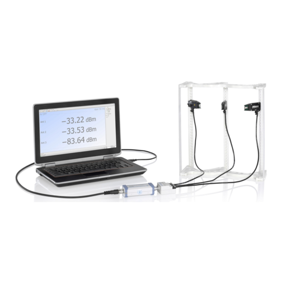
Setting up a measurement This section points out important aspects to consider when setting up an R&S NRPM OTA power measurement. It shows some test setup examples and brief instructions on how to connect the components. You can also find referen- ces to the product page and the user manual of the RF shielded box R&S CMQ200 or an RF test chamber. - Page 38 R&S NRPM Test setup examples Test setups with R&S NRPM3N LAN sensor modules and the R&S NRPM- ZKD3 interface cables for connection to a RF shielded box, require that you use the latest version of the interface cable (1436.2984.02). Single antenna module solution The base configuration with one antenna module measures the power of the inci- dent wave from the DUT to the antenna module, e.g.
- Page 39 R&S NRPM Test setup examples Example: Setup with multiple single polarized R&S NRPM-A90 antenna modules in an RF shielded box (feedthrough modules): Figure 6-2: Multiple R&S NRPM-A90 in an RF shielded box 1 = Controller PC 2 = Sensor modules 3 = RF shielded box User Manual 1425.8663.02 ─...
- Page 40 R&S NRPM Test setup examples Example: Setup with multiple single polarized R&S NRPM-A90 antenna modules in an RF test chamber (interface modules): Figure 6-3: Multiple R&S NRPM-A90 in an RF test chamber 1 = Controller PC 2 = Sensor modules 3 = RF test chamber User Manual 1425.8663.02 ─...
-
Page 41: R&S Cmq200 Shielding Cube
R&S NRPM R&S CMQ200 shielding cube Example: Setup with dual polarized R&S NRPM-A90D antenna modules in an RF shielded box with feedthrough modules: Figure 6-4: Setup with multiple R&S NRPM-A90D in an RF shielded box 1 = Controller PC 2 = Sensor modules... -
Page 42: Connecting An R&S Nrpm Ota Power Measurement Setup
Connecting an R&S NRPM OTA power measure- ment setup To start up an R&S NRPM OTA power measurement, it is assumed that the fol- lowing conditions are met: ● All required hardware is available and ready for use, see Chapter 4.4, "Hard-... -
Page 43: Setting Up The Rf Frontend
Always hold the antenna modules by the housing. When you are working with the dual-polarized antenna modules R&S NRPM-A90D, notice the feeds of the vertical and horizontal antenna modules. You can find out the alignment with the identification numbers "1"... -
Page 44: Setting Up The Connection To The Controller Pc
Setting up the connection to the controller 6.3.2 Setting up the connection to the controller PC The controlling host of the R&S NRPM OTA power measurement solution is a computer, using a supported software for controlling the R&S NRPM3(N) sensor modules, see Chapter 4.4, "Hardware and software... -
Page 45: Using The Usb Connection
® Setting up a measurement R&S NRPM Connecting an R&S NRPM OTA power measurement setup When connecting, consider the following aspects: ● Incorrectly connecting or disconnecting the R&S NRPM3(N) sensor modules can damage the sensor modules or lead to erroneous results. - Page 46 ® Setting up a measurement R&S NRPM Connecting an R&S NRPM OTA power measurement setup Setup Figure 6-5: Setup with an R&S NRP-ZKU 1 = Controller PC 2 = R&S NRP-ZKU 3 = USB host interface connector 4 = R&S NRPM3 sensor module...
-
Page 47: Sensor Hub R&S Nrp-Z5
® Setting up a measurement R&S NRPM Connecting an R&S NRPM OTA power measurement setup 6.3.3.2 Sensor hub R&S NRP‑Z5 The R&S NRP‑Z5 sensor hub (high-speed USB 2.0) can host up to four sensor modules and provides simultaneous external triggering to all connected sensors. -
Page 48: Using The Lan Connection
® Setting up a measurement R&S NRPM Connecting an R&S NRPM OTA power measurement setup Connecting a setup with several sensor modules using the R&S NRP‑Z5 To set up the connection using the sensor hub (Figure 6-6): 1. Connect the R&S NRP‑Z5 to the computer. - Page 49 Setting up a measurement R&S NRPM Connecting an R&S NRPM OTA power measurement setup Depending on the available equipment, you have several options to connect a R&S NRPM3N LAN sensor module to the controller PC. Setup with a PoE Ethernet switch To connect the R&S NRPM3N to a LAN, use a PoE switch, e.g.
- Page 50 ® Setting up a measurement R&S NRPM Connecting an R&S NRPM OTA power measurement setup 2. Connect the controller PC to the Ethernet switch. 3. On the controller, establish a connection between the sensor module and the network, see Chapter 6.3.5, "Establishing a connection to the network",...
- Page 51 Setting up a measurement R&S NRPM Connecting an R&S NRPM OTA power measurement setup Connecting the R&S NRPM3N to the controller PC with the PoE injector and a non-PoE Ethernet switch To connect the sensor module to the controller PC: 1.
-
Page 52: Establishing A Connection To The Network
® Setting up a measurement R&S NRPM Connecting an R&S NRPM OTA power measurement setup = Antenna connector = Antenna module(s) = AC power supply Connecting the R&S NRPM3N to the controller PC with the PoE injector To connect the sensor module to the controller PC: 1. -
Page 53: Using Hostnames
® Setting up a measurement R&S NRPM Connecting an R&S NRPM OTA power measurement setup 2. If the network status LEDs indicate another state, no connection is possible. For reasons and possible solutions, see: ● "Power over Ethernet status LED (8)"... -
Page 54: Assigning The Ip Address
® Setting up a measurement R&S NRPM Connecting an R&S NRPM OTA power measurement setup Example: Serial number of the R&S NRPM3N: 102333 Default hostname: NRPM3N-102333 Hostname in zero configuration networks, including peer-to-peer networks The sensor module supports zero configuration networking, used in networks without DHCP server, such as peer-to-peer networks. -
Page 55: Starting The Measurement
Starting the measurement To start the measurement To start an R&S NRPM OTA power measurement, it is assumed that all compo- nents of the test setup are connected. An easy way for configuring the measurement and displaying results is given by the R&S Power Viewer software:... -
Page 56: Performing Measurements
Measurement applications Performing measurements Sensor module readings The antenna modules R&S NRPM-A90 and R&S NRPM-A90D have an integra- ted diode detector each that converts the RF signal and transmits it directly to the sensor module. You can measure the power of the incident electromagnetic wave towards the antenna module in various quantities: ●... -
Page 57: Using R&S Power Viewer
® Performing measurements R&S NRPM Measurement applications The following sections introduce the power measurement with the R&S Power Viewer and the WebGUI (web browser-based user interface). Section Chapter 11, "Programming examples", on page 168 describes the corresponding programming examples for working in remote control mode. See the R&S Power Viewer manual for more information on how to use the various func-... - Page 58 ® Performing measurements R&S NRPM Measurement applications Outlined are: ● To start the application. ● To configure an OTA single sensor ContAV measurement, for using the R&S NRPM3(N) with up to three antenna modules. ● To configure an OTA multi sensor ContAV measurement, for using of up to four sensor modules with up to three antenna modules each.
- Page 59 ® Performing measurements R&S NRPM Measurement applications 2. In the lower border toolbar, select the sensor module. 3. Execute zeroing: Note: Turn off all measurement power signals before zeroing. An active mea- surement during zeroing causes an error. a) Turn off the measurement signal.
- Page 60 ® Performing measurements R&S NRPM Measurement applications The measurement results window displays measured power in the sensor module channels. To configure an OTA multi sensor ContAV measurement In the toolbar, select the "OTA Multi Sensor" button to open the panel for the OTA measurements with several sensor modules.
- Page 61 ® Performing measurements R&S NRPM Measurement applications 2. In the lower border toolbar, select the sensor module. 3. In the panel on the right, select the channel. 4. Enable the antenna modules of the selected channel. 5. If necessary, set the parameters provided for the measurement mode.
- Page 62 ® Performing measurements R&S NRPM Measurement applications The measurement results window displays the results of the multi channel measurement. To configure an OTA single sensor trace power measurement In the toolbar, select the button to open the panel for trace measurements.
- Page 63 ® Performing measurements R&S NRPM Measurement applications The R&S Power Viewer displays the trace measurement results windows, and the setting parameters in the panel on the right. 2. In the lower border toolbar, select the sensor module. 3. In the panel on the right, select the antenna modules for the measurement.
-
Page 64: Using The Web Browser-Based User Interface
® Performing measurements R&S NRPM Measurement applications The results window displays the trace measurement results of the three antenna modules. 7.2.2 Using the web browser-based user interface Requires a sensor module with networking capabilities, a R&S NRPM3N sensor module. The web browser-based user interface is an alternative way to operate an R&S NRPM3N LAN sensor module. - Page 65 ® Performing measurements R&S NRPM Measurement applications ● Safari 5.1 or later You can use the web browser-based user interface with all devices and operating systems, including tablets and smart phones that are connected to the same net- work. Starting a measurement 1.
-
Page 66: Main Dialog Of The Web Browser-Based User Interface
® Performing measurements R&S NRPM Measurement applications The following chapters describe the functions and parameters of the web browser-based user interface in detail. ● Main dialog of the web browser-based user interface........66 ● Setting the unit....................67 ● Common settings.................... 68 ●... -
Page 67: Setting The Unit
® Performing measurements R&S NRPM Measurement applications The parameters pane provides the setting parameters for the corresponding func- tion selected in the navigation pane. The result pane displays the measurement readings either numerically or graphi- cally, depending on the selected measurement mode. -
Page 68: Common Settings
® Performing measurements R&S NRPM Measurement applications Unit multiples Keyboard key micro nano Example: To set the unit to 1 GHz, enter 1g. For certain units, you can select a different representation, depending on the requirements. For example, for the representation of the "Trigger Level", you can choose Watt, dBm or dBµV. - Page 69 ® Performing measurements R&S NRPM Measurement applications System Status.......................69 Measurement......................69 Frequency......................69 Offset........................69 └ <State>...................... 69 └ <Value>......................69 S-Parameter......................70 Averaging......................70 System Status Displayed in the title bar. Confirms that there is a connection between the sensor and the remote computer and that the sensor is recognized by the software.
-
Page 70: Measurement Modes
® Performing measurements R&S NRPM Measurement applications S-Parameter Note: S-parameter compensation is not supported by the R&S NRPM3 sensor modules. Averaging Chapter 10.8.1, "Configuring averaging", on page 144. 7.2.2.4 Measurement modes Provides the parameters for the supported measurement modes. ●... - Page 71 ® Performing measurements R&S NRPM Measurement applications Duty Cycle Sets the duty cycle, the percentage of one period during which the signal is active, for pulse modulated signals. If activated, the sensor calculates the signal pulse power from its value and the average power.
-
Page 72: Settings
® Performing measurements R&S NRPM Measurement applications Trace Offset Time Sets the relative position of the trigger event in relation to the beginning of the trace measurement sequence. Used to specify the start of recording for the trace mode. Remote command: on page 142 [SENSe<Sensor>:]TRACe:OFFSet:TIME... - Page 73 Chapter 10.8.3, "Configuring corrections", on page 147 ● Chapter 10.13, "Calibrating/zeroing the R&S NRPM3(N) sensor module", on page 165 ● Chapter 10.12, "Testing the R&S NRPM OTA Power Measurement Solu- tion", on page 165 Antenna........................ 73 Zero Calibration....................73 Sensor Information....................73 Antenna Activates an antenna module module for the measurement.
- Page 74 ® Performing measurements R&S NRPM Measurement applications Averaging settings Describes the parameters for automatic averaging. Access: ► In the settings navigation pane of the web browser-based user interface, select "Averaging". The remote commands required to define the averaging settings are descri- bed in Chapter 10.8.1, "Configuring...
- Page 75 ® Performing measurements R&S NRPM Measurement applications Averaging Mode Indicates that the R&S NRPM3N works in manual averaging mode and enables you to set the average count, also considered as averaging factor. Chapter 10.8.1, "Configuring averaging", on page 144. <Mode> ← Averaging Mode Displays the averaging mode.
- Page 76 ® Performing measurements R&S NRPM Measurement applications Access: ► In the settings navigation pane of the web browser-based user interface, select "Trigger". The remote commands required to define the trigger settings are described in: ● Chapter 10.10, "Configuring the trigger", on page 151 ●...
-
Page 77: System Settings
® Performing measurements R&S NRPM Measurement applications Trigger Level Sets the trigger threshold for internal triggering derived from the test signal. Remote command: on page 157 TRIGger:LEVel on page 157 TRIGger:LEVel:UNIT Trigger Delay Sets the delay between the trigger event and the actual start of the measurement. - Page 78 ® Performing measurements R&S NRPM Measurement applications Access: ► In the settings navigation pane of the web browser-based user interface, select "System". The remote commands required to define the system settings are described in Chapter 10.4.1, "Configuring the system", on page 101.
- Page 79 ® Performing measurements R&S NRPM Measurement applications DHCP Selects the mode for assigning the IP address. "Auto" Assigns the IP address automatically, provided the network sup- ports DHCP (dynamic host configuration protocol). "Static" Enables you to assign the IP address manually.
- Page 80 ® Performing measurements R&S NRPM Measurement applications When completed, the web browser-based user interface displays a report with the test results. Remote command: on page 165 TEST:SENSor? User Manual 1425.8663.02 ─ 07...
- Page 81 ® Firmware update R&S NRPM Updating the firmware Firmware update ● Hardware and software requirements............. 81 ● Updating the firmware..................81 Hardware and software requirements To perform a firmware update, you need: ● Connectors and cables for establishing a connection to the PC, see Chap- ter 6.3.2, "Setting up the connection to the controller...
- Page 82 ® Firmware update R&S NRPM Updating the firmware ● Using the firmware update for R&S NRP family program....... 82 ● Using the web browser-based user interface..........84 ● Using remote control..................85 8.2.1 Using the firmware update for R&S NRP family program The Firmware update for R&S NRP family program is part of the R&S NRP Tool-...
- Page 83 ® Firmware update R&S NRPM Updating the firmware 3. If the sensor module you want to update is not listed, perform one of the fol- lowing actions: a) Make sure the sensor module is physically connected. b) Select "Rescan". This function starts a new search for sensor modules.
- Page 84 ® Firmware update R&S NRPM Updating the firmware Troubleshooting R&S NRPM3N LAN sensor module not detected You do not find the sensor module in the list of sensor modules provided by firm- ware update for R&S NRP family. The driver assigned to the sensor module is the legacy driver.
- Page 85 ® Firmware update R&S NRPM Updating the firmware 3. In the navigation pane, select "System". 4. Select "Firmware Update". 5. In the "Firmware Update" dialog, select "Select RSU file". 6. In the file browser, select the *.rsu file for upload.
- Page 86 ® Firmware update R&S NRPM Updating the firmware The size of the file is 10242884. This number has 8 digits. Thus, the <block_data> consist of the following: ● # ● 8 How many digits follow to specify the file size.
- Page 87 Remote control of sensor modules enables you to integrate them into custom automatic test equipment (ATE) systems. For remote control communication between the R&S NRPM and the controlling host, you can use various interfaces and protocols to establish the connection.
- Page 88 ® Network and remote operation R&S NRPM Remote control interfaces and protocols Table 9-1: Remote control interfaces and protocols Interface Supported by Protocols, VISA address string and library R&S NRPM3 USBTMC R&S NRPM3N USB::<vendor ID>::<product ID>:: <serial number>[::INSTR] VISA ●...
- Page 89 ® Network and remote operation R&S NRPM Remote control interfaces and protocols The syntax of the used USB resource string is: USB::<vendor ID>::<product ID>::<serial number>[::INSTR] Where: ● <vendor ID> is the vendor ID for Rohde & Schwarz (0x0AAD). ● <product ID> is the product ID for the Rohde & Schwarz sensor module.
- Page 90 ® Network and remote operation R&S NRPM Remote control interfaces and protocols unique identifier, composed of the specific IP address of the sensor module and some network and VISA-specific keywords. TCPIP::<IP address or hostname>[::<LAN device name>][::INSTR] ● TCPIP designates the network protocol used ●...
- Page 91 ® Network and remote operation R&S NRPM Remote control interfaces and protocols Socket communication TCPIP::<IP address or hostname>::port::SOCKET ● port determines the used port number ● SOCKET indicates the raw network socket resource class Socket communication requires the specification of the port (commonly referred to as port number) and of "SOCKET"...
- Page 92 ® Network and remote operation R&S NRPM Remote control interfaces and protocols uses two TCP sockets for a single connection - the first for fast data transfer, the second one for non-sequential control commands (e.g. Device Clear or SRQ). HiSLIP has the following characteristics: ●...
- Page 93 ● Conformity Commands that are taken from the SCPI standard are indicated as SCPI con- firmed. All commands used by the R&S NRPM follow the SCPI syntax rules. ● Asynchronous commands A command which does not automatically finish executing before the next command starts executing (overlapping command) is indicated as an Asyn- chronous command.
- Page 94 ® Remote control commands R&S NRPM Notations Table 10-1: Units Noted default Corresponding basic unit unit Frequency Seconds Watts Angle degrees Percent DBUV dBuV 10.2 Notations For a detailed description of SCPI notations, see Chapter A, "Remote control basics", on page 195.
- Page 95 ® Remote control commands R&S NRPM Notations Example: Command [SENSe<Sensor>:][POWer:][AVG:]SMOothing:STATe 1 can be written as: SENSe1:POWer:AVG:SMOothing:STATe 1 SENS:POW:AVG:SMO:STAT 1 SENSe:POWer:SMOothing:STATe 1 SENSe:SMOothing:STATe 1 SMOothing:STATe 1 SMO:STAT 1 Parameters Parameters must be separated from the header by a "white space". If several parameters are specified in a command, they are separated by a comma (,).
-
Page 96: Cls
® Remote control commands R&S NRPM Common commands 10.3 Common commands The common commands are taken from the IEEE 488.2 (IEC 625–2) standard. The headers of these commands consist of an asterisk * followed by three letters. Remote Commands: ........................96 *CLS ........................96... -
Page 97: Esr
® Remote control commands R&S NRPM Common commands Sets the event status enable register to the specified value. The query returns the contents of the event status enable register in decimal form. Parameters: <register> Range: 0 to 255 *RST: *ESR? -
Page 98: Opt
® Remote control commands R&S NRPM Common commands The query form returns a "1" when all previous commands have been processed. It is important that the read timeout is set sufficiently long. Since *OPC? waits until all previous commands are executed, "1" is returned in all cases. -
Page 99: Rst
® Remote control commands R&S NRPM Common commands Setting parameters: <number> Range: 0 to 9 *RST: Usage: Setting only *RST Reset Sets the instrument to a defined default status. The default settings are indicated in the description of commands. The command corresponds to the command. -
Page 100: Stb
® Remote control commands R&S NRPM Common commands *STB? STatus Byte query Returns the contents of the status byte in decimal form. Usage: Query only *TRG TRiGger Triggers a measurement. This command is only valid if the power sensor is in the waiting for trigger state and the trigger source is set to BUS SeeTRIGger:SOURce >... - Page 101 ® Remote control commands R&S NRPM Configuring the general functions Usage: Event 10.4 Configuring the general functions 10.4.1 Configuring the system The SYSTem subsystem contains a series of commands for general functions that do not directly affect the measurement. Remote commands: ............102...
-
Page 102: System:communicate:network:ipaddress
® Remote control commands R&S NRPM Configuring the general functions .....................112 SYSTem:MINPower? ..................112 SYSTem:PARameters? ................113 SYSTem:PARameters:DELTa? ....................113 SYSTem:PRESet ....................113 SYSTem:REBoot ....................113 SYSTem:RESTart ..................113 SYSTem:SERRor:LIST:ALL? ................114 SYSTem:SERRor:LIST[:NEXT]? ....................114 SYSTem:SERRor? ....................114 SYSTem:TLEVels? ................114 SYSTem:TRANsaction:BEGin ...................114 SYSTem:TRANsaction:END ....................115 SYSTem:VERSion? ..................115... -
Page 103: System:communicate:network:ipaddress:info
® Remote control commands R&S NRPM Configuring the general functions Example: SYSTem:COMMumicate:NETWork:IPADdress: GATeway '192.168.10.254' Sets 192.168.10.254 as IP address of the default gateway. Manual operation: "Gateway" on page 78 SYSTem:COMMunicate:NETWork:IPADdress:INFO? R&S NRPM3N LAN sensor modules only Queries the network status information. -
Page 104: System:communicate:network:reset
® Remote control commands R&S NRPM Configuring the general functions STATic, you can SYSTem:COMMunicate:NETWork:IPADdress:MODE set the subnet mask manually. Parameters: <netmask> Example: SYSTem:COMMunicate:NETWork:IPADdress: SUBNet:MASK '255.255.255.0' Sets 255.255.255.0 as subnet mask. Manual operation: "Subnet Mask" on page 78 SYSTem:COMMunicate:NETWork:RESet R&S NRPM3N LAN sensor modules only Resets the LAN network settings to the default values. -
Page 105: System:communicate:network[:Common]:Domain
® Remote control commands R&S NRPM Configuring the general functions SYSTem:COMMunicate:NETWork[:COMMon]:DOMain <domain> R&S NRPM3N LAN sensor modules only Determines the primary suffix of the network domain. Parameters: <domain> Example: SYSTem:COMMunicate:NETWork:COMMon:DOMain "abcd.net" SYSTem:COMMunicate:NETWork[:COMMon]:HOSTname <hostname> R&S NRPM3N LAN sensor modules only Sets an individual hostname for the sensor module. -
Page 106: System:error:all
® Remote control commands R&S NRPM Configuring the general functions SYSTem:ERRor:ALL? Queries all unread entries in the error/event queue and removes them from the queue. The response is a comma-separated list of error numbers and a short description of the error in the first in first out order. -
Page 107: System:error[:Next]
In addition, Rohde & Schwarz provides dedicated programs for loading new firm- ware into a R&S NRPM sensor module (e.g. PureFW). If you want to integrate a firmware update function in your own application, use the SYSTem:FWUPdate command. - Page 108 ● An appended delimiter (LF, 0x0a). Example: If you want to update the firmware of the R&S NRPM, you first need an update file, e.g. nrpm3_FW_15.02.12.01.rsu. Lets assume that this file has a size of 10242884 bytes. To send the file to the sensor module for updating the firmware to the new one, your application must assemble a memory block.
-
Page 109: System:fwupdate:status
® Remote control commands R&S NRPM Configuring the general functions SYSTem:FWUPdate:STATus? While a firmware update is in progress, the LED of the sensors flashes in bright white color. When the firmware update is completed, you can read the result of the update with the SYST:FWUP:STAT? command. -
Page 110: System:info
® Remote control commands R&S NRPM Configuring the general functions SYSTem:INFO? [<item>] Returns information about the system. SYSTem:INFO?<string_value> is used to query a specific information item. Without <string_value>, the command returns all available information in a list string, separated by commas. -
Page 111: System:language
® Remote control commands R&S NRPM Configuring the general functions SYSTem:LANGuage <language> Selects an emulation of a different command set. Parameters: <language> SCPI *RST: SCPI SYSTem:LED:CHANnel<Channel>:COLor <color> Sets the color of the antenna module LED. The suffix <channel> selects the corresponding antenna module, and the suffix <color>... -
Page 112: System:led:mode
® Remote control commands R&S NRPM Configuring the general functions Example: SYSTem:LED:MODE USER Selects "User" mode for the system status LED. SYSTem:LED:COLor #HA000A0 Sets the LED color to magenta. SYSTem:LED:COLor #H00C000 Sets the LED color to green. SYSTem:LED:MODE SENSor Sets the system status LED operating mode back to the sensor internal settings. -
Page 113: System:parameters:delta
® Remote control commands R&S NRPM Configuring the general functions SYSTem:PARameters:DELTa? Lists all commands that differ from the defined default status set by *RST. The commands are output with default values, limits and ranges. Usage: Query only SYSTem:PRESet Triggers a sensor reset. -
Page 114: System:serror:list[:Next]
® Remote control commands R&S NRPM Configuring the general functions SYSTem:SERRor:LIST[:NEXT]? Queries the list of all static errors that have occurred but have already been resolved for the eldest entry and removes it from the queue. The response con- sists of an error number and a short description of the error. -
Page 115: System:version
® Remote control commands R&S NRPM Configuring the general functions Usage: Event SYSTem:VERSion? Queries the SCPI version the sensor's command set complies with. Example: SYSTem:VERSion? Queries the SCPI version. Response: 1999.0 The sensor complies with the SCPI version from 1999. - Page 116 ® Remote control commands R&S NRPM Configuring the general functions Suffix: <Channel> 1...3 Usage: Query only Manual operation: "Antenna" on page 73 [SENSe<Sensor>:]CHANnel<Channel>[:ENABle] <state> Deactivates channels without an antenna module connected. Note: A sensor module channel which does not have a connected antenna mod- ule causes a static error condition.
- Page 117 ® Remote control commands R&S NRPM Configuring the general functions 10.4.4 Setting the power unit The UNIT subsystem contains command for setting up the power unit. UNIT:POWer <unit> Sets the output unit for the measured power values. Parameters: <unit> DBM | W *RST: 10.4.5 Setting the result format...
- Page 118 ® Remote control commands R&S NRPM Controlling the measurement FORMat:SREGister <sregister> Specifies the format used for the return value of *STB?. Parameters: <sregister> ASCii | HEXadecimal | OCTal | BINary *RST: ASCii FORMat[:DATA] [<data,length>, <length>] Specifies whether block data is transferred in plain text or binary format.
- Page 119 ® Remote control commands R&S NRPM Controlling the measurement The following chapter introduces in general the principle of triggering and the con- trolling mechanisms for the output of the measurement results. 10.5.1 Triggering In a basic continuous measurement, the measurement is started immediately after the initiate command.
- Page 120 ® Remote control commands R&S NRPM Controlling the measurement Measurement start Depending on whether you want to measure continuously or want to execute one dedicated measurement, select the corresponding command: ● on page 151 INITiate:CONTinuous Starts a new measurement cycle automatically after the previous one has been completed.
- Page 121 ® Remote control commands R&S NRPM Controlling the measurement 10.5.2 Controlling the measurement results The R&S NRPM3(N) sensor module can cope with the wide range of measure- ment scenarios with the help of the so-called "termination control". Depending on how fast your measurement results change, you can define, how to retrieve the measurement results.
- Page 122 ® Remote control commands R&S NRPM Controlling the measurement 10.5.3.1 Continuous average mode General settings for these examples: ● INITiate:CONTinuous ON ● [SENSe<Sensor>:]AVERage:COUNt 4 ● [SENSe<Sensor>:]AVERage[:STATe] ON Example: Repeating termination control Further settings for this example: ● [SENSe<Sensor>:]AVERage:TCONtrol REPeat The measurement is started by the trigger event. Due to the chopper phases, one measurement lasts twice the defined aperture time.
- Page 123 ® Remote control commands R&S NRPM Controlling the measurement Example: Moving termination control Further settings for this example: ● [SENSe<Sensor>:]AVERage:TCONtrol MOVing ● TRIGger:COUNt 16 Every measurement is started by a trigger event. Due to the chopper phases, one measurement lasts twice the defined aperture time. During each measurement,...
- Page 124 ® Remote control commands R&S NRPM Controlling the measurement Example: Average count = 1 [SENSe<Sensor>:]AVERage:COUNt 1 For average count 1, the setting of the termination control has no impact. In both cases, the measurement runs for the duration of one aperture time. Then, settled data are available, and the sensor module returns to the idle state.
- Page 125 ® Remote control commands R&S NRPM Controlling the measurement Example: Repeating termination control Further settings for this example: ● (termination con- [SENSe<Sensor>:]TRACe:AVERage:TCONtrol REPeat trol REPeat is mandatory in trace mode) Every chopper phase is started by a trigger event and lasts the defined trace time.
- Page 126 ® Remote control commands R&S NRPM Controlling the measurement Example: Moving termination control Further settings for this example: ● [SENSe<Sensor>:]TRACe:AVERage:TCONtrol MOVing Every chopper phase is started by a trigger event and lasts the defined trace time. During a chopper phase, the trigger synchronization is high (TRIGger: ON).
- Page 127 ® Remote control commands R&S NRPM Selecting a measurement mode and retrieving results Example: Average count = 1 [SENSe<Sensor>:]TRACe:AVERage:COUNt 1 For average count 1, the setting of the termination control has no impact. In both cases, the measurement runs for the duration of one trace time. Then, settled trace data are available, and the sensor module returns to the idle state.
- Page 128 ® Remote control commands R&S NRPM Selecting a measurement mode and retrieving results Example: Selecting a measurement mode *RST // Select continuous average mode SENSe:FUNCtion "POWer:AVG" INITiate FETCh? Remote commands: ................. 128 [SENSe<Sensor>:]FUNCtion ............129 FETCh<Channel>[:SCALar][:POWer][:AVG]? .............129 FETCh<Sensor>:ALL[:SCALar][:POWer][:AVG]? ....................129 CALCulate:FEED ................
- Page 129 ® Remote control commands R&S NRPM Selecting a measurement mode and retrieving results FETCh<Channel>[:SCALar][:POWer][:AVG]? Queries the measurement results of a particular channel of the sensor module. Suffix: <Channel> 1...3 Usage: Query only FETCh<Sensor>:ALL[:SCALar][:POWer][:AVG]? Queries the measurement results of all channels of a sensor module.
- Page 130 Equivalent isotropically received power P in W or dBm (default): Equivalent detected power of an isotropic antenna with an ideal power detector at the phase center location of the R&S NRPM antenna module assuming radiation only from boresight direction. "PDENsity"...
- Page 131 ® Remote control commands R&S NRPM Selecting a measurement mode and retrieving results Parameters: <mode> *RST: "PISotropic" Example: CALC:MATH "PDEN" Selects power density in W/m as the equivalent resulting unit. CALCulate:MATH[:EXPRession]:CATalog? Lists all supported calculation functions. The result is a list of strings, separated by comma.
- Page 132 ® Remote control commands R&S NRPM Configuring the measurement modes 10.7 Configuring the measurement modes The following chapter describes the settings needed for configuring a measure- ment mode. 10.7.1 Configuring a continuous average measurement The "Continuous Average" mode measures the signal average power asynchro- nously within definable time intervals (sampling windows).
-
Page 133: [Sense
® Remote control commands R&S NRPM Configuring the measurement modes can have a considerable influence, even if the sampling window is much larger than the modulation period. Calculating the measurement time The measurement time is calculated as follows: μ s...:][Power:][Avg:]Aperture -
Page 134: [Sense
® Remote control commands R&S NRPM Configuring the measurement modes Example: [SENSe1:][POWer:][AVG:]BUFFer:CLEar Usage: Event [SENSe<Sensor>:][POWer:][AVG:]BUFFer:COUNt? Available in continuous average mode. Queries the number of results that are currently saved in the result buffer. Example: [SENSe1:][POWer:][AVG:]BUFFer:COUNt? Usage: Query only [SENSe<Sensor>:][POWer:][AVG:]BUFFer:DATA? Queries the data of the continuous average result buffer and returns them even if the buffer is not full.:][Power:][Avg:]Buffer:count -
Page 135: [Sense
® Remote control commands R&S NRPM Configuring the measurement modes Parameters: <count> Range: 1 to 8192 *RST: Example: [SENSe<Sensor>:][POWer:][AVG:]BUFFer:SIZE [SENSe<Sensor>:][POWer:][AVG:]BUFFer:STATe <state> Enables or disables the buffered continuous average mode. If the buffer mode is enabled, all results generated by trigger events are collected in the sensor mod- ule until the buffer is filled.:][Power:][Avg:]Buffer:state - Page 136 ® Remote control commands R&S NRPM Configuring the measurement modes ..............136 [SENSe<Sensor>:]LIST:FREQuency ............136 [SENSe<Sensor>:]LIST:FREQuency:POINts? ..............136 CONTrol<Sensor>:FREQuency:MODE [SENSe<Sensor>:]LIST:FREQuency <frequency>... Sets the frequency values for list processing mode. Parameters: <frequency> Range: 0 to 110e9 *RST: 10e9 Default unit: Frequency Example:...
- Page 137 ® Remote control commands R&S NRPM Configuring the measurement modes surement time and measurement points. The entire result is called a "trace". Each trace must be triggered separately. Remote commands: ............137 [SENSe<Sensor>:]TRACe:AVERage:COUNt ............137 [SENSe<Sensor>:]TRACe:AVERage:TCONtrol ............138 [SENSe<Sensor>:]TRACe:AVERage[:STATe] ................138 [SENSe<Sensor>:]TRACe:DATA? ..............142...
- Page 138 To describe the format of the command response, it is important to know some additional information. Besides the average power, the R&S NRPM sensor module can measure addi- tional measurands like "Minimum", "Maximum" or "Random". These additional measurands are denoted as auxiliary measurands and can be selected with the on page 131 command.
- Page 139 R&S NRPM Configuring the measurement modes A trace measurement with the R&S NRPM can therefore be configured to return up to three measurands on each channel/antenna module. As a consequence, the resulting data which is provided by a [SENSe<Sensor>:]TRACe:DATA query can contain between 1 and 9 blocks of measurement data. For example, 1 resulting measurement data block if only one antenna module is used and only average power is to be measured on that channel.
- Page 140 ® Remote control commands R&S NRPM Configuring the measurement modes Explanation: 'THIS IS A TEST' has 14 bytes, and '14' has 2 digits, hence the #214 User-data-content The previous paragraphs described how to separate the "user-data-content" from the header. We keep the designator "user-data-content" in the further description for denoting the totality of the contained measurement results.
- Page 141 ® Remote control commands R&S NRPM Configuring the measurement modes Example: C1Af3260xxxxyyyy Channel 1 The letter ‘A’ to denote the Average-Trace The letter ‘f’ to denote float format 3 bytes for length of the number of points that follows 260 float values (4 bytes each) xxxxyyyy...
- Page 142 ® Remote control commands R&S NRPM Configuring the measurement modes Usage: Query only [SENSe<Sensor>:]TRACe:MPWidth? Queries the attainable time resolution of the trace mode. The result is the small- est possible distance between two pixels, i.e. it is the smallest time interval that can be assigned to a pixel.
- Page 143 ® Remote control commands R&S NRPM Configuring the measurement modes If disabled, each measurement from the sensor module is averaged. If enabled, only one sampling sequence per measurement is recorded, thus increasing the measurement speed. With a higher measurement speed, the measured values of an individual measurement are immediately delivered.
- Page 144 ® Remote control commands R&S NRPM Configuring basic measurement parameters SINC Returns the trace data as the result of a SINC interpolation of the acquired samples. This setting is only reasonable if the selected number of trace points is higher than the num- ber of samples which results from the internal sample rate in the selected trace time.
- Page 145 ® Remote control commands R&S NRPM Configuring basic measurement parameters ..............145 [SENSe<Sensor>:]AVERage:COUNt ...............145 [SENSe<Sensor>:]AVERage:RESet ..............146 [SENSe<Sensor>:]AVERage:TCONtrol ..............146 [SENSe<Sensor>:]AVERage[:STATe] [SENSe<Sensor>:]AVERage:COUNt <count> Sets the number of readings that are averaged for one measured value. The higher the count, the lower the noise, and the longer it takes to obtain a measured value.
- Page 146 ® Remote control commands R&S NRPM Configuring basic measurement parameters In this case, previous measurement results still contained in the averaging filter strongly affect the settling of the display. As a result, the advantage of detecting trends in the measurement result while the measurement is still in progress, is lost.
- Page 147 ® Remote control commands R&S NRPM Configuring basic measurement parameters Parameters: <state> *RST: Manual operation: "<Mode>" on page 75 10.8.2 Setting the frequency The frequency of the signal to be measured is not automatically determined. For achieving better accuracy, the carrier frequency of the applied signal must be set.
- Page 148 Sets the duty cycle for measuring pulse-modulated signals. The duty cycle defines the percentage of one period when the signal is active. If the duty cycle is enabled, the R&S NRPM calculates the signal pulse power from the average power considering the duty cycle in percent.
- Page 149 ® Remote control commands R&S NRPM Starting and ending a measurement The attenuation of an attenuator located ahead of the sensor module (or the cou- pling attenuation of a directional coupler) is considered with a positive offset, i.e. the sensor module calculates the power at the input of the attenuator or the direc- tional coupler.
- Page 150 ® Remote control commands R&S NRPM Starting and ending a measurement ABORt Immediately interrupts the current measurement. Depending on the selected measurement mode, the trigger system of the sensor module exits the measuring state and switches to: ● Idle state...
- Page 151 ® Remote control commands R&S NRPM Configuring the trigger INITiate:CONTinuous <state> Activates the continuous measurement mode. In continuous measurement mode, the sensor module does not change to idle state after a measurement cycle has been completed, but enters the wait for trigger state. When a trigger event occurs, it starts the next measurement cycle.
- Page 152 ® Remote control commands R&S NRPM Configuring the trigger ....................157 TRIGger:IMMediate ..................... 157 TRIGger:LEVel .....................157 TRIGger:LEVel:UNIT ..................157 TRIGger:SENDer:PORT ..................158 TRIGger:SENDer:STATe ....................159 TRIGger:SLOPe ....................159 TRIGger:SOURce ...................160 TRIGger:SYNC:PORT ..................160 TRIGger:SYNC:STATe TRIGger:BURSt:DELay <delay> List processing mode only Sets the initial delay after the start burst until the first measurement starts.
- Page 153 ® Remote control commands R&S NRPM Configuring the trigger TRIGger:ATRigger[:STATe] <state> Activates the artificial trigger. An artificial trigger is generated if the time set with TRIGger:ATRigger:DELay has elapsed after the start of measurement and no trigger event has occurred. Parameters: <state>...
- Page 154 TRIGger:DELay:AUTO <state> Activates the automatic setting of the delay time. If activated, the measurement starts only after the R&S NRPM input is settled. The function determines the delay value automatically. It is ignored if the set time is longer than the automatically determined value.
- Page 155 ® Remote control commands R&S NRPM Configuring the trigger Figure 10-3: Significance of the drop-out time parameter As the mechanism associated with the dropout time parameter is reactivated whenever the trigger threshold is crossed, unambiguous triggering can also be obtained for many complex signals. By contrast, all triggering is suppressed dur- ing the hold-off time.
- Page 156 ® Remote control commands R&S NRPM Configuring the trigger TRIGger:HOLDoff <holdoff> Sets the hold off time, a time period after a trigger event. During the hold off time all further trigger events are ignored, see Figure 10-4. Figure 10-4: Effect of the trigger holdoff time Parameters: <holdoff>...
- Page 157 *RST: Example: TRIGger:LEVel:UNIT W Manual operation: "Trigger Level" on page 77 TRIGger:SENDer:PORT <sender_port> Selects the port where the R&S NRPM provides its internal trigger signal at the output, provided it is trigger sender (see TRIGger:SENDer:STATe). User Manual 1425.8663.02 ─ 07...
- Page 158 PORT. Typically, the trigger sender uses its internal trigger source. But you can also trig- ger the trigger sender externally, since the R&S NRPM provides two external trig- ger connectors. If you trigger the sender externally, use EXTernal1 as external trigger input port (trigger source) and EXTernal2 as trigger sender output port or vice versa.
- Page 159 ® Remote control commands R&S NRPM Configuring the trigger TRIGger:SLOPe <slope> Available only if TRIGger:SOURce INTernal/EXTernal. Determines what is used for triggering, depending on the trigger source: ● INTernal: uses the rising or falling edge of the envelope TRIGger:SOURce power.
- Page 160 ® Remote control commands R&S NRPM Configuring the trigger HOLD Triggers the measurement with the command TRIGger: IMMediate. IMMediate Starts the measurement immediately. INTernal | INT1 | INT2 | INT3 Determines to consider the RF signal level at the specified antenna (1, 2 or 3) for launching a measurement.
-
Page 161: General Status Register Commands
® Remote control commands R&S NRPM Using the status register Make sure that the number of repetitions is the same for all the sensor modules involved in the measurement. Otherwise, the trigger bus is blocked by any sensor module that has completed its measurements before other sensor module and has returned to the IDLE state. -
Page 162: Reading Out The Condition Part
® Remote control commands R&S NRPM Using the status register Positive error numbers indicate sensor module specific errors. Negative error numbers are error messages defined by SCPI. If the error queue is empty, the querry returns 0 ("No error"). Usage: Query only 10.11.2 Reading out the CONDition part... -
Page 163: Controlling The Enable Part
® Remote control commands R&S NRPM Using the status register STATus:OPERation:ULFail[:SUMMary][:EVENt]? STATus:QUEStionable[:EVENt]? STATus:QUEStionable:CALibration[:SUMMary][:EVENt]? STATus:QUEStionable:POWer[:SUMMary][:EVENt]? These commands read out the EVENt section of the status register. At the same time, the commands delete the contents of the EVENt section. Usage: Query only 10.11.4 Controlling the ENABle part... -
Page 164: Controlling The Positive Transition Part
® Remote control commands R&S NRPM Using the status register STATus:DEVice:NTRansition <value> STATus:OPERation:CALibrating:NTRansition <value> STATus:OPERation:NTRansition <value> STATus:OPERation:LLFail:NTRansition <value> STATus:OPERation:MEASuring:NTRansition <value> STATus:OPERation:SENSe:NTRansition <value> STATus:OPERation:TRIGger:NTRansition <value> STATus:OPERation:ULFail:NTRansition <value> STATus:QUEStionable:CALibration:NTRansition <value> STATus:QUEStionable:NTRansition <value> STATus:QUEStionable:POWer:NTRansition <value> These commands control the Negative TRansition part of a register. - Page 165 The transition also writes a 1 into the associated bit of the corresponding EVENt register. Parameters: <value> *RST: 65535 10.12 Testing the R&S NRPM OTA Power Measure- ment Solution The selftest allows a test of the internal circuitry of the sensor......................165 TEST:SENSor? TEST:SENSor? [<Item>] Triggers a selftest of the sensor module.
-
Page 166: Remote Commands
® Remote control commands R&S NRPM Calibrating/zeroing the R&S NRPM3(N) sensor module ● The sensor module has been replaced. ● No zeroing was performed in the last 24 hours. ● Signals of very low power are to be measured, for instance, if the expected measured value is less than 10 dB above the lower measurement range limit. - Page 167 ® Remote control commands R&S NRPM Calibrating/zeroing the R&S NRPM3(N) sensor module While zero calibration is in progress, no queries or other setting commands are allowed. Any communication attempt can run into a timeout. The setting command accepts only the parameter ONCE; OFF and ON are ignored.
- Page 168 Performing measurements in continuous aver- age mode This section describes programming examples for measuring continuous average power with one R&S NRPM. The examples demonstrate the sequences in SCPI syntax, pseudo code, and also show the corresponding source codes for using VISA protocol.
- Page 169 Example: SCPI sequence for measuring the power of three antenna mod- ules The command sequence measures the continuous average power of the three channels of an R&S NRPM. // Query the resource identifier and reset the sensor module to default *IDN? // Response: ROHDE&SCHWARZ,NRPM3,100001,16.09.20.01...
- Page 170 ® Programming examples R&S NRPM Performing measurements in continuous average mode Example: Pseudo code for measuring the power of two antenna modules This example, written in pseudo code, shows a reduced set of basic steps to set up and execute a continuous average measurement.
- Page 171 ® Programming examples R&S NRPM Performing measurements in continuous average mode Example: Python (VISA) source code This sequence shows the Python source code, based on the pseudo code exam- ple above. ################################################################### ## Name: contAv-M3.py ## Purpose: Measuring RF power with the R&S NRPM3 OTA sensor module ## Description: This example demonstrates the use of an R&S NRPM3...
- Page 172 ® Programming examples R&S NRPM Performing measurements in continuous average mode cmd = "SENS:CHAN{}:PRES?".format( antenna + 1 ) res = sensor.ask(cmd) if int(res) == 1: cmd = "SENS:CHAN{}:ENAB ON".format( antenna + 1 ) else: cmd = "SENS:CHAN{}:ENAB OFF".format( antenna + 1 ) sensor.write(cmd)
- Page 173 RF fre- quency points with the R&S NRPM OTA Power Measurement Solution in list mode. The example represents the execution of a R&S NRPM OTA power sensor measurement under VISA environment in pseudo code.
- Page 174 ® Programming examples R&S NRPM Performing measurements in list mode ● Measurement period = time from the beginning until the end of a step at one frequency point ● n = number of frequency points in the list ● X = actual time for a single measurement, calculated according to the formula: X = 2 * AverageCount * (ApertureTime + 100µs)
- Page 175 ® Programming examples R&S NRPM Performing measurements in list mode Example: Pseudo code for measuring the power in list mode This example, written in pseudo code, shows how to set up and execute a power measurement in list mode. ===================================...
- Page 176 ® Programming examples R&S NRPM Performing measurements in list mode double dMeasurementPeriod = 2.0e-3; 2 ms double arFreqList[] = { 24.0e9, 24.5e9, 25.0e9, 25.5e9, 26.0e9, 26.5e9, 27.0e9, 27.5e9, 28.0e9 }; session = OpenfirstNRPM3onUSBorNetwork(); //=================================================================== // *RST and *IDN? WriteCmd(session, "*RST");...
- Page 177 ® Programming examples R&S NRPM Performing measurements in list mode WriteCmd(session, "STAT:OPER:ENAB 16"); //=================================================================== // Setup the Measurement... // Configure Averaging strCmd = "SENS:AVER:COUNT " + str(uiAvgCount); WriteCmd(session, strCmd); WriteCmd(session, "SENS:AVER:STAT ON"); // Aperture time strCmd = "SENS:POW:AVG:APER " + str(dAperture);...
- Page 178 ® Programming examples R&S NRPM Performing measurements in list mode // After the initial start pulse a continuous sequence of // measurements are executed. The number of measurements is // selected by the length of the frequency list -- see entries...
- Page 179 ® Programming examples R&S NRPM Performing measurements in list mode print(Query(session, "SYST:ERR?"); // Check for static errors print(Query(session, "SYST:SERR?"); //=================================================================== // Execute the list mode measurement // resetting the event information by an initial readout Query(session, "STAT:OPER:MEAS:EVEN?"); Query(session, "STAT:OPER:EVEN?"); // Start a measurement WriteCmd(session, "INIT:IMM");...
- Page 180 Performing measurements in trace mode This section describes programming examples for measuring power over time with the R&S NRPM OTA Power Measurement Solution. The examples demon- strate the sequences in SCPI syntax, pseudo code, and also show the source codes for using VISA protocol.
- Page 181 Example: SCPI sequence for measuring the power of three antenna mod- ules The command sequence measures the envelope power over time in the three channels of the R&S NRPM antenna module. // Query the resource identifier and // reset the sensor module to default *IDN? // Response: ROHDE&SCHWARZ,NRPM3,100001,16.09.20.01...
- Page 182 ® Programming examples R&S NRPM Performing measurements in trace mode SYSTem:SERRor? // Stop the continuous measurement. INITiate:CONTinuous OFF Example: Pseudo code for measuring the power of two antenna modules This example, written in pseudo code, shows how to set up and execute a trace power measurement.
- Page 183 ® Programming examples R&S NRPM Performing measurements in trace mode Example: C/C++ (VISA) source code This sequence shows the VISA source code, based on the pseudo code example above. // Determine the resource identifier, e.g. // resource = "NRPM3-100001" // resource identifier = USB0::0x0aad::0x0195::100001 // Open the device viOpen( defaultRM, “USB0::0x0aad::0x0195::100001”, VI_NULL, VI_NULL,&session );...
-
Page 184: Displaying Status Information
Contacting customer support................ 191 12.1 Displaying status information Status information is available in several ways. Status LED of the R&S NRPM The position of the status LED is indicated in Chapter 5, "R&S NRPM tour", on page 28. The meaning of the different colors and blinking frequencies is explained in "Sta-... -
Page 185: Troubleshooting
® Troubleshooting R&S NRPM Problems during a firmware update Do not apply a signal to the sensor module while the selftest is running. Executing the self-test with an active signal assigned, can erroneously result in error messages at the test steps Offset Voltages and/or Noise Voltages. -
Page 186: Cannot Establish A Lan Connection
® Troubleshooting R&S NRPM Cannot establish a LAN connection Firmware update was aborted If there is not enough free memory space, the firmware update aborts. An error message is displayed, and the status LED of the sensor module starts flashing red. -
Page 187: Replacing Antenna Cables
® Troubleshooting R&S NRPM Replacing antenna cables Firmware update You can use the firmware update for R&S NRP family program to load new firm- ware for the sensor modules, see Chapter 8.2.1, "Using the firmware update for R&S NRP family program",... - Page 188 ® Troubleshooting R&S NRPM Replacing antenna cables 12.5.1 Spare parts and recommended tools The available cable replacement kits are listed in the table that follows: Description Part no. Applicable for A90 Applicable for A90D Cable replacement Kit, 550 mm 1436.2855.02 Cable replacement Kit, 750 mm 1436.2855.03...
- Page 189 ® Troubleshooting R&S NRPM Replacing antenna cables 12.5.2 Cable replacement ● There are two versions of the strain relief. The old version is shown on the left hand side of the figures. The new version is shown on the right hand side of the figures.
- Page 190 ® Troubleshooting R&S NRPM Replacing antenna cables Figure 12-3: Placing the new cable 5. NOTICE! Connect the new cable in a linear movement to prevent damage. Connect the new cable until it snaps in. Figure 12-4: Connect new cable 6. NOTICE! Monitor the position of the cable tie head.
-
Page 191: Contacting Customer Support
® Troubleshooting R&S NRPM Contacting customer support Figure 12-6: Position of the cable tie head 8. Cut off the protruding cable tie. Use the electronics side cutter (part no. 78 71 125 or equivalent). 9. NOTICE! We recommend that you execute a selftest after replacing the cables and reassembling the system. - Page 192 ® Troubleshooting R&S NRPM Contacting customer support Figure 12-7: QR code to the Rohde & Schwarz support page User Manual 1425.8663.02 ─ 07...
- Page 193 ® Maintenance, storage and disposal R&S NRPM Disposal Maintenance, storage and disposal The product does not require regular maintenance. It only requires occasional cleaning. It is however advisable to check the nominal data from time to time. 13.1 Cleaning Do not use any liquids for cleaning. Cleaning agents, solvents (thinners, acetone), acids and bases can damage the labeling, plastic parts and display.
- Page 194 ® Maintenance, storage and disposal R&S NRPM Disposal Rohde & Schwarz has developed a disposal concept for the eco-friendly disposal or recycling of waste material. As a manufacturer, Rohde & Schwarz completely fulfills its obligation to take back and dispose of electrical and electronic waste.
- Page 195 ® Remote control basics R&S NRPM SCPI command structure Annex Remote control basics ● SCPI command structure................195 ● Status reporting system................202 SCPI command structure SCPI commands - messages - are used for remote control. Commands that are not taken from the SCPI standard follow the SCPI syntax rules. The R&S NRPM3(N) sensor modules support the SCPI version 1999.
- Page 196 ® Remote control basics R&S NRPM SCPI command structure *ESR? EVENT STATUS QUERY Queries the contents of the event status register. *IDN? IDENTIFICATION QUERY Queries the instrument identification string. A.1.2 Syntax for device-specific commands Long and short form The mnemonics feature a long form and a short form. The short form is marked by upper case letters here, to distinguish it from the long form, which constitutes the complete word.
- Page 197 ® Remote control basics R&S NRPM SCPI command structure Optional mnemonics Some command systems permit certain mnemonics to be inserted into the header or omitted. These mnemonics are marked by square brackets in the description. The instrument must recognize the long command to comply with the SCPI standard.
- Page 198 ® Remote control basics R&S NRPM SCPI command structure ● Text ● Character strings ● Block data The parameters required for each command and the allowed range of values are specified in the command description. Numeric values Numeric values can be entered in any form, i.e. with sign, decimal point and exponent.
- Page 199 ® Remote control basics R&S NRPM SCPI command structure ● NAN Not A Number (NAN) represents the value 9.91E37. NAN is only sent as a instrument response. This value is not defined. Possible causes are the divi- sion by zero, the subtraction of infinite from infinite and the representation of missing values.
- Page 200 ® Remote control basics R&S NRPM SCPI command structure Block data Block data is a format which is suitable for the transmission of large amounts of data. A command using a block data parameter has the following structure: Example: SYSTem:HELP:SYNTax:ALL? Response: #45168xxxxxxxx The ASCII character # introduces the data block.
- Page 201 ® Remote control basics R&S NRPM SCPI command structure The hash symbol introduces binary, octal, hexadecimal and block data. ● Binary: #B10110 ● Octal: #O7612 ● Hexa: #HF3A7 ● Block: #21312 A "white space" (ASCII-Code 0 to 9, 11 to 32 decimal, e.g. blank) separates the header from the parameters.
- Page 202 ® Remote control basics R&S NRPM Status reporting system Example: TRIG:LEV 0.1E-3 TRIG:DEL 3E-3 A.1.6 Responses to queries A query is defined for each setting command unless explicitly specified otherwise. It is formed by adding a question mark to the associated setting command.
- Page 203 ® Remote control basics R&S NRPM Status reporting system A.2.1 Hierarchy of the status registers Fig.A-1 shows the hierarchical structure of information in the status registers. User Manual 1425.8663.02 ─ 07...
- Page 204 ® Remote control basics R&S NRPM Status reporting system Device Sensor Error Summary Status Sensor Error Sensor Error Sensor Error Sensor Error Legacy Locked Reference-PLL Locked Questionable Output-Queue Status Power Summary Calibration Summary POST Failure Error-/Event-Queue Standard Operation Complete Event...
- Page 205 ® Remote control basics R&S NRPM Status reporting system The highest level is formed by the status byte register (STB) and the associated service request enable (SRE) register. The STB receives its information from the standard event status register (ESR)
- Page 206 ® Remote control basics R&S NRPM Status reporting system part can only be read, but not written into or cleared. Its contents are not affected by reading. PTRansition / NTRansition status register part The two transition register parts define which state transition of the CONDition part (none, 0 to 1, 1 to 0 or both) is stored in the EVENt part.
- Page 207 ® Remote control basics R&S NRPM Status reporting system ENABle bit = 1: if the associated EVENt bit is "1", the sum bit is set to "1" as well. This part can be written into and read by the user as required. Its contents are not affected by reading.
- Page 208 ® Remote control basics R&S NRPM Status reporting system Bit No. Meaning Error queue not empty The bit is set if the error queue has an entry. If this bit is enabled by the SRE, each entry of the error queue generates a service request. An error can thus be recognized and specified in detail by querying the error queue.
- Page 209 ® Remote control basics R&S NRPM Status reporting system PPE; bit 6 is also used - in contrast to the SRE. The IST flag is obtained by ORing all results together. The PPE can be set by the *PRE command and read by the *PRE? query.
- Page 210 ® Remote control basics R&S NRPM Status reporting system Bit No. Meaning Reference PLL locked state This bit signals whether the PLL for the clock reference is synchronized. The bit is useful when selecting an external clock source. The following states are possible: ●...
- Page 211 Corresponds to the summary bit of the questionable calibration status register. Chapter A.2.6.2, "Questionable calibration status register", on page 212. POST failure The built-in test of the R&S NRPM carried out automatically upon power-up has generated an error. 10 to 15 Not used A.2.6.1...
- Page 212 ® Remote control basics R&S NRPM Status reporting system A.2.6.2 Questionable calibration status register The EVENt register and the CONDition register contain information whether the zero offset of a sensor module is still valid. Querying the register: ● STATus:QUEStionable:CALibration:CONDition? ●...
- Page 213 ® Remote control basics R&S NRPM Status reporting system Bit No. Meaning Execution error This bit is set if the syntax of a received command is correct but the command cannot be executed due to various marginal conditions. An error message with a number between -200 and -300 denoting the error in greater detail is entered in the error queue.
- Page 214 ® Remote control basics R&S NRPM Status reporting system Bit No. Meaning 7 to 9 Not used Sense status register summary bit This bit is set if a sensor module is initialized. Chapter A.2.8.4, "Operation sense status register", on page 217.
- Page 215 ® Remote control basics R&S NRPM Status reporting system User Manual 1425.8663.02 ─ 07...
- Page 216 ® Remote control basics R&S NRPM Status reporting system A.2.8.1 Operation calibrating status register The CONDition register contains information about whether a sensor module is currently being calibrated and, depending on the configuration of the transition register. The EVENt register indicates whether a calibration was started or com- pleted since the last readout of this register.
- Page 217 ® Remote control basics R&S NRPM Status reporting system A.2.8.3 Operation trigger status register The CONDition register contains information about whether a sensor module is currently in the waiting for trigger state, i.e. expecting a trigger event and, depending on the configuration of the transition register. The EVENt register indi- cates whether the waiting for trigger state was entered or quit by a sensor module since the last readout of the register.
- Page 218 ® Remote control basics R&S NRPM Status reporting system Table A-11: Meaning of bits used in the operation sense status register Bit No. Meaning Not used sensor module initializing The sensor module is being initialized. 5 to 15 Not used A.2.8.5...
- Page 219 ® Remote control basics R&S NRPM Status reporting system Table A-13: Meaning of bits used in the operation lower limit fail status register Bit No. Meaning Not used Upper limit fail The measured value exceeds the upper limit value. 5 to 15 Not used User Manual 1425.8663.02 ─...
- Page 220 ® Glossary: List of used terms and abbreviations R&S NRPM Glossary: List of used terms and abbrevia- tions anechoic chamber: Non-reflective, non-echoing box (RF shielded box) or cham- (RF test chamber) that absorbs reflections of radio frequencies, used to test antennas, radars or electromagnetic interference.
- Page 221 R&S NRP-Toolkit: Software package, which provides drivers for Linux, Mac OS X or MS Windows. Remote control: The operation of the R&S NRPM by remote control commands or programs to perform automated tests. The instrument is connected to a system controller via LAN/VXI-11, GPIB or USB using Virtual Instrument Software Archi- tecture (VISA).
- Page 222 ® Glossary: List of used terms and abbreviations R&S NRPM RF shielded box: Anechoic test box with very low reflectivity. Provides a shielded test environment for OTA measurements of radio frequencies. RF test chamber: Larger anechoic RF test chamber up to RF test room sizes with very low reflectivity.
- Page 223 ® Glossary: List of used terms and abbreviations R&S NRPM Anechoic chamber with very low reflectivity. Provides a shielded test environment for OTA measurements of radio frequencies. User Manual 1425.8663.02 ─ 07...
- Page 224 ® List of commands R&S NRPM List of commands [SENSe<Sensor>:][POWer:][AVG:]APERture................133 [SENSe<Sensor>:][POWer:][AVG:]BUFFer:CLEar..............133 [SENSe<Sensor>:][POWer:][AVG:]BUFFer:COUNt?..............134 [SENSe<Sensor>:][POWer:][AVG:]BUFFer:DATA?..............134 [SENSe<Sensor>:][POWer:][AVG:]BUFFer:INFO?..............134 [SENSe<Sensor>:][POWer:][AVG:]BUFFer:SIZE..............134 [SENSe<Sensor>:][POWer:][AVG:]BUFFer:STATe..............135 [SENSe<Sensor>:][POWer:][AVG:]SMOothing:STATe...............135 [SENSe<Sensor>:]AUXiliary...................... 131 [SENSe<Sensor>:]AVERage:COUNt..................145 [SENSe<Sensor>:]AVERage:RESet..................145 [SENSe<Sensor>:]AVERage:TCONtrol..................146 [SENSe<Sensor>:]AVERage[:STATe]..................146 [SENSe<Sensor>:]CHANnel<Channel>:PRESence?..............115 [SENSe<Sensor>:]CHANnel<Channel>[:ENABle]..............116 [SENSe<Sensor>:]CORRection:DCYCle...................148 [SENSe<Sensor>:]CORRection:DCYCle:STATe................148 [SENSe<Sensor>:]CORRection:OFFSet................... 149 [SENSe<Sensor>:]CORRection:OFFSet:STATe................
- Page 225 ® List of commands R&S NRPM *IST?............................97 *OPC............................97 *OPT?............................98 *PRE.............................98 *RCL.............................98 *RST.............................99 *SAV............................. 99 *SRE.............................99 *STB?............................100 *TRG............................100 *TST?............................100 *WAI............................100 ABORt............................150 CALCulate:FEED........................129 CALCulate:MATH[:EXPRession]....................130 CALCulate:MATH[:EXPRession]:CATalog?................131 CALibration<1...4>:DATA......................166 CALibration<1...4>:DATA:LENGth?....................166 CALibration<Channel>:ZERO:AUTO..................166 CONTrol<Sensor>:FREQuency:MODE..................136 FETCh<Channel>[:SCALar][:POWer][:AVG]?................129 FETCh<Sensor>:ALL[:SCALar][:POWer][:AVG]?..............
- Page 226 ® List of commands R&S NRPM STATus:OPERation:LLFail:ENABle....................163 STATus:OPERation:LLFail:NTRansition..................164 STATus:OPERation:LLFail:PTRansition..................164 STATus:OPERation:LLFail[:SUMMary][:EVENt]?...............162 STATus:OPERation:MEASuring:CONDition?................162 STATus:OPERation:MEASuring:ENABle................... 163 STATus:OPERation:MEASuring:NTRansition................164 STATus:OPERation:MEASuring:PTRansition................164 STATus:OPERation:MEASuring[:SUMMary][:EVENt]?.............. 162 STATus:OPERation:NTRansition....................164 STATus:OPERation:PTRansition....................164 STATus:OPERation:SENSe:CONDition?................... 162 STATus:OPERation:SENSe:ENABle..................163 STATus:OPERation:SENSe:NTRansition...................164 STATus:OPERation:SENSe:PTRansition...................164 STATus:OPERation:SENSe[:SUMMary][:EVENt]?..............162 STATus:OPERation:TRIGger:CONDition?................. 162 STATus:OPERation:TRIGger:ENABle..................163 STATus:OPERation:TRIGger:NTRansition.................164 STATus:OPERation:TRIGger:PTRansition.................164 STATus:OPERation:TRIGger[:SUMMary][:EVENt]?..............162 STATus:OPERation:ULFail:CONDition?..................162 STATus:OPERation:ULFail:ENABle................... 163 STATus:OPERation:ULFail:NTRansition..................164 STATus:OPERation:ULFail:PTRansition..................164 STATus:OPERation:ULFail[:SUMMary][:EVENt]?..............
- Page 227 ® List of commands R&S NRPM STATus:QUEStionable:PTRansition...................164 STATus:QUEStionable[:EVENt]?....................163 STATus:QUEue[:NEXT]?......................161 SYSTem:COMMunicate:NETWork:IPADdress................102 SYSTem:COMMunicate:NETWork:IPADdress:GATeway............102 SYSTem:COMMunicate:NETWork:IPADdress:INFO?............... 103 SYSTem:COMMunicate:NETWork:IPADdress:MODE............... 103 SYSTem:COMMunicate:NETWork:IPADdress:SUBNet:MASK..........103 SYSTem:COMMunicate:NETWork:RESet..................104 SYSTem:COMMunicate:NETWork:RESTart................104 SYSTem:COMMunicate:NETWork:STATus?................104 SYSTem:COMMunicate:NETWork[:COMMon]:DOMain............105 SYSTem:COMMunicate:NETWork[:COMMon]:HOSTname............105 SYSTem:DFPRint<Channel>?....................105 SYSTem:ERRor:ALL?........................ 106 SYSTem:ERRor:CODE:ALL?.....................106 SYSTem:ERRor:CODE[:NEXT]?....................106 SYSTem:ERRor:COUNt?......................106 SYSTem:ERRor[:NEXT]?......................107 SYSTem:FWUPdate........................107 SYSTem:FWUPdate:STATus?....................109 SYSTem:HELP:HEADers?......................109 SYSTem:HELP:SYNTax:ALL?....................109 SYSTem:HELP:SYNTax?......................109 SYSTem:INFO?..........................
- Page 228 ® List of commands R&S NRPM SYSTem:TRANsaction:END....................... 114 SYSTem:VERSion?........................115 SYSTem[:SENSor]:NAME......................115 TEST:SENSor?...........................165 TRIGger:ATRigger:DELay......................152 TRIGger:ATRigger:EXECuted?....................152 TRIGger:ATRigger[:STATe]......................153 TRIGger:BURSt:DELay......................152 TRIGger:COUNt......................... 153 TRIGger:DELay..........................153 TRIGger:DELay:AUTO....................... 154 TRIGger:DTIMe..........................154 TRIGger:EXTernal<2...2>:IMPedance..................155 TRIGger:HOLDoff........................156 TRIGger:HYSTeresis........................156 TRIGger:IMMediate........................157 TRIGger:LEVel........................... 157 TRIGger:LEVel:UNIT........................157 TRIGger:SENDer:PORT......................157 TRIGger:SENDer:STATe......................158 TRIGger:SLOPe......................... 159 TRIGger:SOURce........................159 TRIGger:SYNC:PORT........................160...
- Page 229 Dual polarized ........31 USB ............ 46 Instrument tour ........31 Connection LED ............. 33 Measurement setup ......42 NRPM-A90, NRPM-A90D ....31 Connector Single polarized ........31 Antenna ..........29 Antenna module cable ......36 Host interface ........29 Antenna module cable connector LAN .............
- Page 230 Web browser-based user interface ..84 NRPM antenna modules .....31 Firmware update for R&S NRP family ..82 NRPM-Z3 ..........35 Firmware update for R&S NRP family pro- NRPM-Z3 connected to NRM3 ... 36 gram NRPM-ZD3 ......... 33 Firmware update ......... 82 NRPM3 ..........28 Intended use ..........
- Page 231 Instrument tour ........35 Trace ........... 71 Interface module ......... 35 Measurement setup Strain relieve ........36 Connection ..........42 NRPM-Z3 connected to NRM3 NRPM ..........37 Instrument tour ........36 Overview ..........37 NRPM-ZD3 RF shielded box ........41 Cable connector ........34 Measurement tasks Feedthrough module ......34...
- Page 232 ® Index R&S NRPM NRPM3N Software requirements ......20 LAN connector ........30 Unpacking and checking .....17 LAN reset ..........30 Prevent antenna damage ......18 Network status LED ......30 Printed circuit board PoE LED ..........31 Antenna module ........33 NTRansition ...........206...
- Page 233 Ethernet (LAN) interface ..... 89 Instrument tour ........28 HiSLIP protocol ........91 Setting Interfaces ..........87 See parameter ........67 NRPM ..........87 Setting up Protocols ..........87 RF shielded box ........43 Socket communication ......92 RF test chamber ......... 44 USB interface ........88...
- Page 234 ® Index R&S NRPM Trace programming examples (pseudo Trace code) ..........182 Parameters ......... 71 Trace programming examples (SCPI) Single sensor measurement ....62 ............181 Trigger I/O connector .......30 Socket Trigger1 ........... 29 Communication ........92 Troubleshooting ........184 Resource string ........91...
- Page 235 ® Index R&S NRPM Welcome Key features ........12 OTA power measurement solution ..12 Zero configuration networking ....52 User Manual 1425.8663.02 ─ 07...
Need help?
Do you have a question about the NRPM and is the answer not in the manual?
Questions and answers