Table of Contents
Advertisement
Quick Links
Advertisement
Table of Contents

Related Manuals for R&S NRT2


Summary of Contents for R&S NRT2
- Page 1 ® R&S NRT2 Power Reflection Meter Getting Started (>N5×2) 1430057302 Version 03...
- Page 2 Rohde & Schwarz GmbH & Co. KG. Trade names are trademarks of the owners. ® 1430.0573.02 | Version 03 | R&S NRT2 Throughout this manual, products from Rohde & Schwarz are indicated without the ® symbol , e.g. ® R&S NRT2 is indicated as R&S NRT2.
-
Page 3: Table Of Contents
® Contents R&S NRT2 Contents 1 Safety and Regulatory Information........5 1.1 Safety Instructions................5 1.2 Labels on the Product................8 1.3 Warning Messages in the Documentation..........8 1.4 Korea Certification Class B..............9 2 Documentation Overview............10 2.1 Getting Started Manual...............10 2.2 User Manual..................10 2.3 Tutorials.................... - Page 4 ® Contents R&S NRT2 4.7.1 NRT Sensor Connector.................18 4.7.2 USB 2.0 Host Interfaces............... 19 4.8 Connecting USB and External Devices..........20 4.9 Switching On or Off................20 5 Instrument Tour..............22 5.1 Front Panel Tour..................22 5.1.1 NRT Sensor..................22 5.1.2 Touchscreen..................23 5.1.3 Keys......................
-
Page 5: Safety And Regulatory Information
Intended use Combined with a supported R&S NRT‑Zxx directional power sensor, the R&S NRT2 base unit is intended for power and reflection measurements in develop- ment and for monitoring and maintenance purposes. The supported R&S NRT‑Zxx directional power sensors are listed in the data sheet. Observe the operating conditions and performance limits stated in the data sheet. - Page 6 ® Safety and Regulatory Information R&S NRT2 Safety Instructions the instructions provided here and in the product documentation. Keep the prod- uct documentation nearby and offer it to other users. Use the product only for its intended use and within its performance limits. Inten- ded use and limits are described in the product documentation such as the data sheet, manuals and the printed "Safety Instructions".
- Page 7 ® Safety and Regulatory Information R&S NRT2 Safety Instructions If the product has foldable feet, always fold the feet completely in or out to ensure stability. The feet can collapse if they are not folded out completely or if the prod- uct is moved without lifting it.
-
Page 8: Labels On The Product
® Safety and Regulatory Information R&S NRT2 Warning Messages in the Documentation Cleaning the product Use a dry, lint-free cloth to clean the product. When cleaning, keep in mind that the casing is not waterproof. Do not use liquid cleaning agents. -
Page 9: Korea Certification Class B
® Safety and Regulatory Information R&S NRT2 Korea Certification Class B WARNING Potentially hazardous situation. Could result in death or serious injury if not avoi- ded. CAUTION Potentially hazardous situation. Could result in minor or moderate injury if not avoided. -
Page 10: Documentation Overview
R&S NRT2 product page at: www.rohde-schwarz.com/manual/NRT2 Getting Started Manual Introduces the R&S NRT2 and describes how to set up and start working with the product. A printed version is delivered with the instrument. User Manual Contains the description of all instrument modes and functions. -
Page 11: Printed Safety Instructions
Data Sheets and Brochures The data sheet contains the technical specifications of the R&S NRT2. It also lists the firmware applications and their order numbers, and optional accessories. The brochure provides an overview of the instrument and deals with the specific characteristics. -
Page 12: Key Features
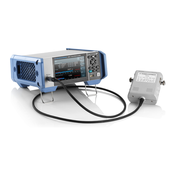
Directional power measurements, measuring forward and reverse power under operating conditions, are required when installing, servicing and monitoring trans- mitters, antennas and RF generators. The compact R&S NRT2 power reflection meter supports all the measurement functions of the R&S NRT‑Zxx directional power sensors. -
Page 13: Preparing For Use
Lifting and Carrying "Lifting and carrying the product" on page 6. The R&S NRT2 weighs below 3 kg, details are provided in the data sheet. Due to the low weight, you can move the R&S NRT2 easily. Unpacking and Checking 1. -
Page 14: Choosing The Operating Site
4.4.1 Placing the Product on a Bench Top The R&S NRT2 is a small and lightweight product. You can stack the R&S NRT2 with other products, but place the R&S NRT2 on top. In the following procedure, the weight indication for stacking refers to the most common design of larger Rohde &... - Page 15 ® Preparing for Use R&S NRT2 Setting Up the Product To place the product on a bench top 1. Place the product on a stable, flat and level surface. Ensure that the surface can support the weight of the product. For information on the weight, see the data sheet.
-
Page 16: Mounting The Product In A Rack
® Preparing for Use R&S NRT2 Considerations for Test Setup ● Do not place the product next to heat-generating equipment such as radia- tors or other products. 4.4.2 Mounting the Product in a Rack To prepare the rack 1. Observe the requirements and instructions in "Setting up the product"... -
Page 17: Connecting To Power
Use a conductive floor mat and heel strap combination. Connecting to Power The R&S NRT2 can be used with different AC power voltages and adapts itself automatically to them. Adjusting the R&S NRT2 to a particular AC supply voltage is therefore not required. -
Page 18: Connecting Power Sensors
NRT2 Connecting Power Sensors Connecting Power Sensors The R&S NRT2 supports the R&S NRT‑Zxx directional power sensors listed in the data sheet. You have two choices for connecting the power sensors, but only one measurement at a time is possible. -
Page 19: Usb 2.0 Host Interfaces
Figure 5-1 Chapter 5.2.4, "USB Host Interface", on page 27. 1. Connect the R&S NRT‑Z5 USB interface adapter to the R&S NRT‑Zxx power sensor. 2. Connect the USB connector of the adapter to the R&S NRT2. Getting Started 1430.0573.02 ─ 03... -
Page 20: Connecting Usb And External Devices
® Preparing for Use R&S NRT2 Switching On or Off 3. Connect the R&S NRT‑Zxx power sensor between source and load. See Chapter 4.7.1, "NRT Sensor Connector", on page 18. Connecting USB and External Devices Apart from connecting power sensors, you can use the USB interfaces to connect USB devices. - Page 21 ® Preparing for Use R&S NRT2 Switching On or Off 3. If you want to return to a defined initial state, perform a preset. To shut down the product The product is in the ready state. ► Press the [standby] key.
-
Page 22: Instrument Tour
"Cursor keys" on page 24. 5.1.1 NRT Sensor See (1) in Figure 5-1. To the left of the display, the R&S NRT2 provides the sensor interface. For sup- ported power sensors, see the product brochure. Getting Started 1430.0573.02 ─ 03... -
Page 23: Touchscreen
See (2) in Figure 5-1. The R&S NRT2 displays results in panes. Depending on the measurement mode, values are displayed digitally or graphically. False triggers can occur If an object (e.g. a human finger) that is charged with static electricity is brought near the touch panel, false triggers can occur. - Page 24 [Preset] Opens the "Save / Recall / Preset" dialog. If you press [Preset] again, the preset function starts. If you press the [Preset] key during booting, the R&S NRT2 starts with the factory default state. [Zero] Pressing [Zero] opens the "Zeroing Sensors" dialog.
-
Page 25: Usb Host Interface
® Instrument Tour R&S NRT2 Front Panel Tour 5.1.4 USB Host Interface See (5) in Figure 5-1. USB 2.0 (universal serial bus) interface of the type A (host USB). Used to con- nect: ● R&S NRT‑Zxx power sensor using the R&S NRT‑Z5 USB interface adapter ●... -
Page 26: Rear Panel Tour
NRT2 Rear Panel Tour Rear Panel Tour Figure 5-2: Rear panel of the R&S NRT2 1 = Trig In / Out 2 and Out 1 / Trig Out connectors, see Chapter 5.2.1, "Trig In / Out 2 and Out 1 / Trig Out Connectors",... -
Page 27: Ethernet Interface
"Connecting to power" on page 7. When the R&S NRT2 is connected to the AC supply, it automatically sets itself to the correct range for the applied voltage. The range is printed on the casing. There is no need to set the voltage manually. -
Page 28: Name Plate
5.2.7 Name Plate See (7) in Figure 5-2. Shows the type, identification and name of the R&S NRT2. The device ID con- sists of: <stock number> - <serial number> - <checksum> The framed 6 digits in Figure 5-3 are the individual serial number. -
Page 29: Contacting Customer Support
® Contacting Customer Support R&S NRT2 Contacting Customer Support Technical support – where and when you need it For quick, expert help with any Rohde & Schwarz product, contact our customer support center. A team of highly qualified engineers provides support and works with you to find a solution to your query on any aspect of the operation, program- ming or applications of Rohde &... -
Page 30: Index
® Index R&S NRT2 Index Symbols Front panel keys ........23 1 Trig key ..........23 Getting started ......... 10 AC power supply ........27 Connecting to ........17 Help ............10 Hostname Default ..........28 Bench top operation ........ 14 Brochures .......... - Page 31 ® Index R&S NRT2 Open source acknowledgment (OSA) ..11 Operating conditions ....... 14 Operating site .......... 14 Out 1 / Trig Out connector ....... 26 Power supply Connecting to ........17 Preparing for use ........13 Preset key ..........24 Rack mounting ........
Need help?
Do you have a question about the NRT2 and is the answer not in the manual?
Questions and answers