Table of Contents
Advertisement
Quick Links
E-880TM-3-E
Ins. No.
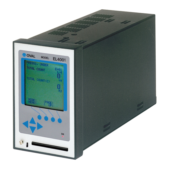
FLOW COMPUTER EL4001 SERIES
KEY OPERATION MANUAL
Every OVAL Flow Computer is fabricated and shipped from our factory under stringent
quality control. To derive maximum benefit from the computer, we recommend that you
become familiar with this instruction manual before you place it in service and retain a
copy at the field location for ready reference.
Advertisement
Table of Contents

Related Manuals for Oval EL4101


Summary of Contents for Oval EL4101
- Page 1 FLOW COMPUTER EL4001 SERIES KEY OPERATION MANUAL Every OVAL Flow Computer is fabricated and shipped from our factory under stringent quality control. To derive maximum benefit from the computer, we recommend that you become familiar with this instruction manual before you place it in service and retain a...
- Page 2 BEFORE YOU BEGIN This manual has been prepared for OVAL flow computers of the EL4001 series. Making sure of your model number and good understanding of the input/output and calculation process according to the instruction manual for the model, refer only to the specific topics of interest.
-
Page 3: Table Of Contents
5.3 Device Information Screen (INFO) ......................24 5.4 On-Screen Information of Respective Models ..................... 25 5.4.1 EL4101 Steam Service Flow Computer (saturated steam service) ............25 5.4.2 EL4111 Steam Service Flow Computer (superheated steam service) ..........26 5.4.3 EL4121 Temperature/Pressure Compensated Flow Computer (gas service) ........27 5.4.4 EL4131 Liquid Temperature Compensated Flow Computer .............. - Page 4 E-880TM-3-E (3) EL4121 Temperature/Pressure Compensated Flow Computer (gas service) ........37 (4) EL4131 Liquid Temperature Compensated Flow Computer ..............38 (5) EL4201 Temperature/Pressure Compensated Flow Computer (measured in terms of mass) ....38 (6) EL4211 Liquid Temperature Compensated Flow Computer (measured in terms of mass) ....39 (7) EL4301 Density Computer for Mass Flowmeter..................
- Page 5 E-880TM-3-E (3) Instant flowrate measurement submenu screen ................... 67 ① Instant flowrate measurement - type setup (MEASURE. TYPE) ............68 ② Instant flowrate measurement - low cutoff frequency (LOW-CUT FREQ.) ........69 ③ Instant flowrate measurement - total count stop setup (COUNT STOP) ........... 69 ④...
- Page 6 E-880TM-3-E 6.4.17 Instant Flowrate Setup (FLOW RATE) ....................95 (1) Instant flowrate submenu screen ......................95 ① Instant flowrate unit setup (UNIT) ....................95 6.4.18 Temperature Compensation Setup (TEMP. COMPENSATE) ............97 (1) Temperature compensation submenu screen ..................97 ①...
- Page 7 7.2 SYS Mode Submenu Screen ........................143 7.3 SYS Mode Menu Tree ..........................144 7.3.1 EL4101 Steam Service Flow Computer (saturated steam service) ............. 144 7.3.2 EL4111 Steam Service Flow Computer (superheated steam service) ..........144 7.3.3 EL4121 Temperature/Pressure Compensated Flow Computer (gas service) ........145 7.3.4 EL4131 Liquid Temperature Compensated Flow Computer ..............
- Page 8 E-880TM-3-E 7.4.3 Simulated Analog Output (SIMULATE) ....................153 (1) Simulated analog output submenu screen ..................153 ① Analog output 1 (ANA. OUT 1) ......................153 7.4.4 Temperature Input Setup (TEMP. INPUT) ................... 154 (1) Temperature input submenu screen ....................154 ①...
- Page 9 10.2 DIP Switch Identification .......................... 183 11. OVERALL MENU TREE STRUCTURES ...................... 184 11.1 EL4101 Steam Service Flow Computer (saturated steam service) ............184 11.2 EL4111 Steam Service Flow Computer (superheated steam service) ............ 185 11.3 EL4121 Temperature/Pressure Compensated Flow Computer (gas service) ......... 187 11.4 EL4131 Liquid Temperature Compensated Flow Computer ..............
-
Page 10: Key Arrangement
E-880TM-3-E 1. KEY ARRANGEMENT 1.1 Front Panel Part Names Display screen Function keys Arrow keys Card slot 1.2 Function Keys In the EL4001 series, software-defined function keys are used: they have different functions as the user moves from screen to screen. The four round keys located directly below the display are the functions keys. -
Page 11: Display Screen
E-880TM-3-E 2 . DISPLAY SCREEN ... -
Page 12: Card Insertion
E-880TM-3-E 2.3 Card Insertion The status of 1C card insertion is indicated. ・Hidden: IC card not inserted in place ・Message: IC card inserted in place ... -
Page 13: Status Of Reception
E-880TM-3-E 2.6 Status of Reception With communication interface provided, reception of a communication command is shown. ※ Not shown in models without communication capabilities. ・Receive: Home address of a communication command is the operator himself. ... -
Page 14: About Intial Checks
E-880TM-3-E 3 . ABOUT INITIAL CHECKS Each EL4001 series computer runs a series of initial performance checks at startup or power cycling. In this initiation process, tests are performed on possible problems associated with CPU performance in the computer, parameters and process variables stored in the memory, problems in the memories themselves, and memory read/write. -
Page 15: Ram (Extended Program Area) Hardware Check
E-880TM-3-E 3.1.2 RAM (extended program area) Hardware Check ←A screen showing a memory check error ... -
Page 16: Prom (Calibration Data Area) Hardware Check
| | | repetitions of power cycling, a fault in the internal circuitry is suspected; seek our service at the nearest OVAL representative in your area. 3.1.7 E PROM (total count and error logging data area) Data Check ←A screen showing a memory check error... -
Page 17: Prom (System Config. Area) Data Check
| | | OK CAUTION: Once the model setup program has been cleared, computation cannot be performed. If this is the case, reload the model setup program from the model setup card. Seek our service at the nearest OVAL representative in your area. -
Page 18: About Mode Selection
SET mode and SYS mode remain disabled unless DIP switch settings are in the OFF. 4.2 Mode Tree Shown below is a mode select menu relative to individual modes. On Models EL4101, EL4111, EL4121, EL4131, EL4201, EL4211, EL4301, EL4311, and EL4321 RUN mode SET mode SYS mode Mode select menu screen... -
Page 19: On-Screen Fields
E-880TM-3-E On Models EL4501 and EL4511 RUN mode SET mode SYS mode Mode select menu screen KEY card Param. card inserted in place Calib. card inserted in place inserted in place EXTD mode Parameter set mode PRM card 4.3 On-Screen Fields Shown below is the mode select menu screen. Date (YY-MM-DD) ... -
Page 20: When Password Setting Is On
E-880TM-3-E 4.3.1 When Password Setting is ON When the password setting is ON, some labels indicating the functions of function keys appear highlighted. (About the password setting, see the section on PASSWORD SETTING for the SYS mode.) ←Mode select menu screen ... -
Page 21: Inserting A Card Into The Drive
E-880TM-3-E 4.3.2 Inserting a Card into the Drive When a card is inserted into the drive, a label, identifying the type of the card, appears at the bottom right of the function key field. Example: When the model setup card is inserted. ... -
Page 22: When Parameter Setup Card Is Inserted
E-880TM-3-E (2) When parameter setup card is inserted When parameter setup card is popped into the drive, a label “PRM CARD” appears in the function key field as shown below. ←Mode select menu screen / CD −... -
Page 23: Run Mode Screen
E-880TM-3-E 5. RUN MODE SCREEN 5.1 On-Screen Fields The RUN mode is a mode in which the instant flowrate in instant flowrate calculation, temperature and pressure input values, correction factors, total flow, and their measurement units. Up to three items can be indicated on a single screen. -
Page 24: Device Information Screen (Info)
E-880TM-3-E 5.3 Device Information Screen (INFO) From the error logging screen, you can access the device information screen. ←Error logging list screen, review, history ... -
Page 25: On-Screen Information Of Respective Models
5.4 On-screen Information of Respective Models On-screen information in the RUN mode are described on the pages that follow. 5.4.1 EL4101 Steam Service Flow Computer (saturated steam service) ←RUN mode screen 1 ... -
Page 26: El4111 Steam Service Flow Computer (Superheated Steam Service)
E-880TM-3-E 5.4.2 EL4111 Steam Service Flow Computer (superheated steam service) ←RUN mode screen 1 / ... -
Page 27: El4121 Temperature/Pressure Compensated Flow Computer (Gas Service)
E-880TM-3-E 5.4.3 EL4121 Temperature/Pressure Compensated Flow Computer (gas service) ←RUN mode screen 1 / ... -
Page 28: El4131 Liquid Temperature Compensated Flow Computer
E-880TM-3-E 5.4.4 EL4131 Liquid Temperature Compensated Flow Computer ←RUN mode screen 1 / ... -
Page 29: El4201 Temp. /Press. Compensated Flow Computer (Conversion Into Mass)
E-880TM-3-E 5.4.5 EL4201 Temperature/Pressure Compensated Flow Computer (conversion into mass) ←RUN mode screen 1 / ... -
Page 30: El4211 Liquid Temp. Compensated Flow Computer (Conversion Into Mass)
E-880TM-3-E 5.4.6 EL4211 Liquid Temperature Compensated Flow Computer (conversion into mass) ←RUN mode screen 1 / ... -
Page 31: El4311 Density Computer For Mass Flowmeter (Solids Content Flow Compensated)
E-880TM-3-E 5.4.8 EL4311 Density Computer for Mass Flowmeter (solids content flow compensated) ←RUN mode screen 1 /... -
Page 32: El4321 Density Computer (Oscillating Spool Densitometer, Gas Service)
E-880TM-3-E 5.4.9 EL4321 Density Computer (oscillating spool densitometer, gas service) ←RUN mode screen 1 / ... -
Page 33: El4401 Blend Oil Temperature Compensated Flow Computer
E-880TM-3-E 5.4.10 EL4401 Blend Oil Temperature Compensated Flow Computer ←RUN mode screen 1 / ... -
Page 34: El4501 Multipoint Temperature Compensated Flow Computer
E-880TM-3-E 5.4.11 EL4501 Multipoint Temperature Compensated Flow Computer ←RUN mode screen 1 / ... -
Page 35: El4511 Multipoint Temperature Compensated Flow Computer (With Com Interface)
E-880TM-3-E 5.4.12 EL4511 Multipoint Temperature Compensated Flow Computer (communication interface provided) ←RUN mode screen 1 / ... -
Page 36: Set Mode
E-880TM-3-E 6. SET MODE The SET mode is a mode to set up parameters, such as the parameters required for calculation, input/ output base/full scale, and measurement units. SET mode related processes are carried out while executing the calculation process. 6.1 SET Mode Menu Tree The SET mode consists of the following four levels: 1. -
Page 37: Set Mode Main Menu Screen By Model
E-880TM-3-E 6.2.1 SET Mode Main Menu Setup Items by Model (1) EL4101 Steam Service Flow Computer (saturated steam service) *PRESS. INPUT (pressure input setup) p. 65 ... -
Page 38: El4131 Liquid Temperature Compensated Flow Computer
E-880TM-3-E *QUADRATIC COMPNSATE (quadratic correction factor setup) p. 88 / ... -
Page 39: El4211 Liquid Temperature Compensated Flow Computer (Measured In Terms Of Mass)
E-880TM-3-E (6)EL4211 Liquid Temperature Compensated Flow Computer (measured in terms of mass) *TEMP. INPUT (temperature input setup) p. 48 ... -
Page 40: El4321 Density Computer (Oscillating Spool Densitometer, Gas Service)
E-880TM-3-E *FLOW RATE (SOLID) (instant flowrate (solids content) setup) p. 95 / ... -
Page 41: El4501 Multipoint Temperature Compensated Flow Computer
E-880TM-3-E (11) EL4501 Multipoint Temperature Compensated Flow Computer *TEMP. INPUT (temperature input setup) p. 48 /... -
Page 42: Set Mode Submenu Screen
E-880TM-3-E 6.3 SET Submenu Screen Pressing the function key “ENTR” at the main menu changes the current screen to a submenu screen of the menu item pointed by the cursor. Detailed submenu items in the option and their settings appear. The user can review current settings on this screen. -
Page 43: Numerical Value Setup Screen (Input)
E-880TM-3-E (1) Numerical value setup screen (INPUT) When an item of numerical value setup is chosen at a submenu, this screen appears. The user enters a new setting of numerical value and establishes it on this screen. First, the current value is changed in the numerical value edit field. -
Page 44: ① When "Cler" Is Depressed
E-880TM-3-E ←Numerical value edit / ... -
Page 45: ② When "Cancel" Is Depressed
E-880TM-3-E ② When “CANCEL” is depressed Pressing the function key “CANCEL” causes the screen to go back the submenu screen, aborting the value that has just been modified - even if the on-screen reading set by pressing the function key “ENTR”... -
Page 46: Option Select Screen (Select)
E-880TM-3-E (2) Option select screen (SELECT) When option item select is selected at the submenu screen, this window appears. Your selection from among the options available is set up at this screen. First, the current setting appears below the title of the menu screen. In the following lines at left, options are shown in the option select field. -
Page 47: About On-Screen Submenu Items
E-880TM-3-E 6.3.2 About On-screen Submenu Items On the submenu screen, submenu items corresponding to respecttive main menu items are shown. The items shown here are only those necessary for setup with respect to the current settings; items not necessary for setup are not shown. -
Page 48: Submenu Setup Items
E-880TM-3-E 6.4 Submenu Setup Items 6.4.1 Temperature Input Setup (TEMP. INPUT) As the factors associated with temperature, the measurement units, constants (with the input type set to NONE in the SYS mode), baseline, full scale value, under alarm point, over alarm point, under fallback level, over fallback level, and smoothing factor are established here. -
Page 49: 5Mv/℃ And 10Mv
E-880TM-3-E Temperatures in the RUN mode are indicated relative to the input within the range where the over alarm point and the under alarm point determine its high and low limit, respectively. If an input goes out of this range, the output will automatically be clamped at the over fallback or under fallback value. -
Page 50: Temperature Input Submenu Screen
E-880TM-3-E (4) Temperature input submenu screen At the submenu, move the cursor to the desired item (your option) with the up and down arrow keys. At the touch of function key “ENTR” , the screen switches to the desired setup screen. ... -
Page 51: ① Temperature Input Unit Setup (Unit)
E-880TM-3-E Conditions to show submenu items Submenu item SYS mode input type ※ NONE Other than NONE Unit of measurement Displayed Displayed Constant Displayed Hidden Baseline Hidden Displayed Full scale Hidden Displayed Under alarm point Hidden Displayed Over alarm point Hidden Displayed Under fallback level... -
Page 52: ③ Temperature Input Baseline Setup (Base Scale)
E-880TM-3-E ③ Temperature input baseline setup (BASE SCALE) The baseline with respect to the temperature input is set up here. ←Numerical value input setup ... -
Page 53: ⑥ Temperature Input Over Alarm Point Setup (Over Alarm Point)
E-880TM-3-E ⑥ Temperature input over alarm point setup (OVER ALARM POINT) The over alarm point with respect to the temperature input is set up here. ←Numerical value input setup ... -
Page 54: ⑨ Temperature Input Smoothing Factor Setup (Smoothing Coef.)
E-880TM-3-E ⑨ Temperature input smoothing factor setup (SMOOTHING COEF.) The smoothing factor with respect to the temperature input is set up here. ※ In the SYS mode, this item is not shown if the temperature input type is set to “NONE”. Smoothing factor K=1-... -
Page 55: Pressure Input Setup (`Ress. Input)
E-880TM-3-E 6.4.2 Pressure Input Setup (PRESS. INPUT) As the factors associated with pressure, the measurement units, constants (with the input type set to NONE in the SYS mode), baseline, full scale value, under alarm point, over alarm point, under fallback level, over fallback level, and smoothing factor are established here. -
Page 56: Pressure Input Submenu Screen
E-880TM-3-E (2) Pressure input submenu screen At the submenu, move the cursor to the desired item to be set up with the up and down arrow keys. At the touch of function key “ENTR” , the screen switches to the setup screen of the item desired. ... -
Page 57: ① Pressure Input Unit Setup (Unit)
E-880TM-3-E Conditions to show submenu items Submenu item SYS mode input type ※ NONE Other than NONE Unit of measurement Displayed Displayed Constant Displayed Hidden Baseline Hidden Displayed Full scale Hidden Displayed Under alarm point Hidden Displayed Over alarm point Hidden Displayed Under fallback level... -
Page 58: ② Pressure Input Constant Setup (Constant)
E-880TM-3-E ② Pressure input constant setup (CONSTANT) In the SYS mode, when the input type is set to NONE, constants are set. ※ Constants are fixed values set internally in the equipment contrary to the measurements of external input. -
Page 59: ⑤ Pressure Input Under Alarm Point Setup (Under Alarm Point)
E-880TM-3-E ⑤ Pressure input under alarm point setup (UNDER ALARM POINT) The under alarm point with respect to the pressure input is set up here. ←Numerical value input setup ... -
Page 60: ⑧ Pressure Input Over Fallback Level Setup (Over Fallback)
E-880TM-3-E ⑧ Pressure input over fallback level setup (OVER FALLBACK) The over fallback level with respect to the pressure input is set up here. ←Numerical value input setup ... -
Page 61: Blend Input Setup (Blend Input)
E-880TM-3-E 6.4.3 Blend Input Setup (BLEND INPUT) As the factors associated with blend input, the measurement units, constants (with the input type set to NONE in the SYS mode), baseline, full scale value, under alarm point, over alarm point, under fallback level, and over fallback level are established here. -
Page 62: Blend Input Submenu Screen
E-880TM-3-E (1) Blend input submenu screen At the submenu, move the cursor to the desired item to be set up with the up and down arrow keys. At the touch of function key “ENTR” , the screen switches to the setup screen of the item desired. ... -
Page 63: ① Blend Input Unit Setup (Unit)
E-880TM-3-E ① Blend input unit setup (UNIT) Measurement unit of blend input is selected here. ←Unit option select ... -
Page 64: ④ Blend Input Full Scale Setup (Full Scale)
E-880TM-3-E ④ Blend input full scale setup (FULL SCALE) The full scale value with respect to the blend input is set up here. ←Numerical value input setup ... -
Page 65: ⑦ Blend Input Under Fallback Level Setup (Under Fallback)
E-880TM-3-E ⑦ Blend input under fallback level setup (UNDER FALLBACK) The under fallback level with respect to the blend input is set up here. ←Numerical value input setup ... -
Page 66: Pulse Input Setup (Pulse Input)
E-880TM-3-E 6.4.4 Pulse Input Setup (PULSE INPUT) As the parameter associated with pulses, the meter factor (the weight of input pulses) and the maximum frequency of input pulses are set up here. (1)Pulse input submenu item screen At the submenu, move the cursor to the desired setup item with the up arrow and down arrow keys. At the touch of function key “ENTR”... -
Page 67: Instant Flowrate Measurement Setup (Flow Rate Setting)
E-880TM-3-E 6.4.5 Instant Flowrate Measurement Setup (FLOW RATE SETTING) As the parameter values associated with instant flowrate calculation, the type of measurement, low cutoff frequency, totalizing interruption, smoothing factor, maximum frequency setup, number of measurement cycles, interpolation setup, and reference oscillator correction are set up here. Instant flowrate measurement comes in the following two user selectable approaches: 1. -
Page 68: ① Instant Flowrate Measurement - Type Setup (Measure. Type)
E-880TM-3-E / ... -
Page 69: ② Instant Flowrate Measurement - Low Cutoff Frequency (Low-Cut Freq.)
E-880TM-3-E ② Instant flowrate measurement - low cutoff frequency (LOW-CUT FRQ.) The count stop in instant flowrate measurement is set up here. ←Numerical value input setup ... -
Page 70: ⑤ Instant Flowrate Measurement - Max. Period Setup (Max. Period)
E-880TM-3-E ⑤ Instant flowrate measurement - max. period setup (MAX. PEERIOD) The maximum period in instant flowrate measurement is set up here. Beyond this time period, obtained frequency measurements are automatically clamped at zero. ... -
Page 71: ⑧ Instant Flowrate Measurement - Ref Oscillator Corr. Factor Setup (Ref. Oscillator)
E-880TM-3-E Interpolation – “to read between the lines” - involves a process to run a periodic check for the presence of incoming pulses at intervals of 100 ms; calculate the period based on the elapsed time at the time of check when pulses are missing for a duration beyond the previously measured period of time. -
Page 72: Density Pulse Input (Dens. Pulse Input)
E-880TM-3-E 6.4.6 Density Pulse Input (DENS. PULSE INPUT) As the parameters associated with density pulse input, the measurement unit and correction factor for the reference oscillator are set up here. ※ These settings are used in Models EL4301, EL4311, and EL4321. They are not used in other models. -
Page 73: ② Density Pulse Input Internal Ref. Oscillator Corr. Factor (Ref. Oscillator)
E-880TM-3-E ② Density pulse input – internal reference oscillator correction factor (REF. OSCILLATOR) The correction factor of internal reference oscillator used in (the) period measurement of density pulse input is set up here. - How internal reference oscillator (5MHz) is corrected - While the reference clock in instant flowrate measurement is 5MHz, slight errors exist between flow computers. -
Page 74: Total Count Setup (Total Count)
E-880TM-3-E 6.4.7 Total Count Setup (TOTAL COUNT) Total count related items are set up here. ※ The settings to be made here influence the total counter reading in the RUN mode and the scaling (frequency division) factor of pulse output. Use extra care about the pulse output scale factor when you attempt to alter modify these settings. - Page 75 ・Available measuring units Model Total count reading Options “TOTAL COUNT1” :Corrected total mass flow g, kg, t, lb EL4101 “TOTAL COUNT2” :Corrected total calorific flow cal, kcal, Mcal, J, kJ, MJ “TOTAL COUNT1” :Corrected total mass flow g, kg, t, lb EL4111 “TOTAL COUNT2”...
-
Page 76: Analog Output Setup (Analog Output)
E-880TM-3-E 6.4.8 Analog Output Setup (ANALOG OUTPUT) As the parameters associated with analog output, the measuring units, baseline, full scale value, upper high limit of the output, lower low limit of the output, and low cutoff level are set here, The lower low and upper high level limits determine the current magnitude with respect to the instant flowrate value. -
Page 77: ① Analog Output Unit Setup (Unit)
Analog output submenu screen p. 76 Available measurement units Model Available measurement unit options Analog output options (SYS mode) EL4101 kg/h, kg/min, g/h, g/min, t/h, t/min, lb/h, lb/min Instant mass flowrate (fixed ※ 1) EL4111 kg/h, kg/min, g/h, g/min, t/h, t/min, lb/h, lb/min Instant mass flowrate (fixed ※... -
Page 78: ② Analog Output Baseline Setup (Base Scale)
E-880TM-3-E ② Analog output baseline setup (BASE SCALE) The baseline of analog output is set up here. ←Numerical value input setup ... -
Page 79: ⑤ Analog Output Low Limit Setup (Low Limit (Ma))
E-880TM-3-E ⑤ Analog output low limit setup (LOW LIMIT (mA)) The low limit of analog output is set up here. ←Numerical value input setup ... -
Page 80: Compensation Setup (3Α Compensate)
E-880TM-3-E 6.4.9 3α compensation setup (3α COMPENSATE) As factors associated with 3α compensation, the correction type, coefficients α and β, and reference temperature are set here. If term 2α + βis used in the correction formula, select correction type α ≠ β; if 3α... -
Page 81: ① 3Α Correction Type Setup (Type)
E-880TM-3-E ① 3α compensation - type setup (TYPE) The 3α compensation type is set up here. Select either α = β or α ≠ β. ←Correction type option select ... -
Page 82: ④ 3Α Correction Ref. Temperature Setup (Ref. Temp.)
E-880TM-3-E ④ 3α compensation – reference temperature setup (REF. TEMP.) The reference temperature of 3α compensation is set up here. ←Numerical value input setup ... -
Page 83: Temp./Press. Correction Setup (T/P Compnsate)
E-880TM-3-E 6.4.10 Temperature/Pressure Compensation Setup (T/P COMPEN.) As parameters associated with temperature and pressure compensation, the reference temperature and pressure are set up here. <Calculation formula> p + 0.101325 + 273.15 K= × + 0.101325 t + 273.15 ... -
Page 84: ② Temp./Press. Correction Ref. Pressure Setup (Ref. Press.)
E-880TM-3-E ② Temperature/pressure compensation – reference pressure setup (REF. PRESS.) The reference pressure of T/P compensation is set up here. ←Numerical value input setup ... -
Page 85: Meter Error Correction Setup (Meter Error)
E-880TM-3-E 6.4.11 Meter Factor Correction Setup (METER ERROR) As the parameters associated with the meter error correction factors, the frequencies 1 through 9, constants (the correction type set to “CONSTANT” ), and meter errors 1 through 9 (the correction type set to a line graph “POINT TO POINT”... -
Page 86: ① Meter Error Correction Type Setup (Type)
E-880TM-3-E ② Correction type set to a constant (CONSTANT) / ... -
Page 87: ③ Meter Error Correction - Frequency Setup 1 Thru 9 (Frequency 1 Thru 9)
E-880TM-3-E ③ Meter error correction - frequencies 1 thru 9 setup (FREQUENCY 1 thru 9) When the correction type is set to a line graph “POINT TO POINT” , frequencies are set up here. ※ The measurement unit to be set here is “Hz”. Make sure of the unit before you set up. ←Numerical value input setup ... -
Page 88: Quadratic Correction Setup (Quadratic Compensate)
E-880TM-3-E 6.4.12 Quadratic Correction Coefficients (QUADRATIC COMPEN) As the parameters associated with quadratic correction factors, coefficients Pa, Pb, Pc, Ta, Tb, and Tc are set here. <Calculation Formula> X= (Pa+Pb×p+Pc×p ) ×(Ta+Tb×t+Tc×t ) where p:Line pressure(MPa) t :Line temperature(℃)... -
Page 89: ① Quadratic Correction - Factor Pa Setup (Coefficient (Pa))
E-880TM-3-E ① Quadratic correction - coefficient Pa setup (COEFFICIENT (Pa)) Quadratic correction coefficient Pa is set up here. ※ The pressure unit for this coefficient is “MPa”. ... -
Page 90: ④ Quadratic Correction - Factor Ta Setup (Coefficient (Ta))
E-880TM-3-E ④ Quadratic correction - coefficient Ta setup (COEFFICIENT (Ta)) Quadratic correction coefficient Ta is set up here. ※ The temperature unit for this coefficient is “°C”. ... -
Page 91: Saturated Steam Density Setup (Spec. Weight (Sat))
E-880TM-3-E 6.4.13 Saturated Steam Density Setup (SPEC. WEIGHT (SAT)) As the parameters associated with the density of saturated steam, their measurement units are set up here. ※ The units to be set here are on-screen units in the RUN mode, and they by no means affect calculation and other settngs. -
Page 92: Superheated Steam Density Setup (Spec. Weight (Sup))
E-880TM-3-E 6.4.14 Superheated Steam Density Setup (SPEC. WEIGHT (SUP)) As the parameters associated with the density of superheated steam, their measurement units are set up here. ※ The units to be set here are on-screen units in the RUN mode, and they by no means affect ... -
Page 93: Saturated Steam Specific Enthalpy Setup (Spec. Enthalpy (Sat))
E-880TM-3-E 6.4.15 Saturated Steam Specific Enthalpy Setup (SPEC. ENTHALPY (SAT)) As the parameters associated with saturated steam specific enthalpy calulation, their measurement units are set up here. ※ The units to be set here are on-screen units in the RUN mode, and they by no means affect calculation and other settings. -
Page 94: Superheated Steam Specific Enthalpy Setup (Spec. Enthalpy (Sup))
E-880TM-3-E 6.4.16 Superheated Steam Specific Enthalpy Setup (SPEC. ENTHALPY (SUP)) As the parameters associated with the specific ethalpy of superheated steam, their measurement units are set up here. ※ The units to be set here are on-screen units in the RUN mode, and they by no means affect ... -
Page 95: Instant Flowrate Setup (Flow Rate)
E-880TM-3-E 6.4.17 Instant Flowrate Calculation Setup (FLOW RATE) Parameters associated with instant flowrate computation are set up here. ※ The item to be set at this window applies to the instant flowrate indicated, not to the instant flowrate calculation of analog output. - Page 96 ・Available measurement units Model Instant flowrate Unit options available “FLOW RATE” :Corrected instant mass EL4101 kg/h, kg/min, g/h, g/min, t/h, t/min, lb/h, lb/min flowrate “FLOW RATE” :Corrected instant mass EL4111 kg/h, kg/min, g/h, g/min, t/h, t/min, lb/h, lb/min flowrate “FLOW RATE”...
-
Page 97: Temperature Compensation Setup (Temp. Compensate)
E-880TM-3-E 6.4.18 Temperature Compensation Setup (TEMP. COMPEN.) As the parameters associated with coefficients of temperature compensation, coefficients a, b, and c are set up here. ※ These settings are used only in Models EL4131 and EL4211. The settings are not shown in other models. -
Page 98: ① Temperature Compensation - Refeference Temperature Setup (Ref. Temp.)
E-880TM-3-E ① Temperature compensation - reference temperature setup (REF. TEMP.) The reference temperature of temperature compensation coefficient is up here. ※ For the unit to be set here, the unit set at the temperature input unit setup (① Temperature input unit setup (UNIT) on page 51) is used. -
Page 99: ④ Temperature Compensation - Coefficient C Setup (Coefficient (C))
E-880TM-3-E ④ Temperature compensation - coefficient c setup (COEFFICIENT (c) ) Coefficient c of temperature compensation coefficient is set here. ←Numerical value setup ... -
Page 100: Density Setup (Mass Conversion Factor) (Density)
E-880TM-3-E 6.4.19 Density Setup (mass conversion factor) (DENSITY) Density and (its) density unit are set up here. ※ These settings are used only in Models EL4201 and EL4211. The settinge are not shown in other models. (1)Density setup submenu screen ... -
Page 101: ② Density (Density)
E-880TM-3-E ② Density (DENSITY) Density is set up here. ←Numerical value input setup / ... -
Page 102: Density Calculation Setup (Density Parameter) El4301
E-880TM-3-E 6.4.20 Density Calculation Setup (DENSITY PARAMETER), EL4301 Along with the parameters associated with density calculation, the alarm points and fallback levels for the corrected density are set up here. ※ These settings are used only in Model EL4301. They are not shown in other models. <Calculation Formula>... -
Page 103: Density Calculation Setup Submenu Screen
E-880TM-3-E Conditions to show submenu items Submenu item Input type in the SYS mode ※ None Pulse input Unit Displayed Displayed Constant Displayed Hidden Baseline Hidden Displayed Full scale Hidden Displayed Under alarm point Hidden Displayed Over alarm point Hidden Displayed Under fallback level... - Page 104 E-880TM-3-E / ...
-
Page 105: ① Density Calculation - Unit Setup (Unit)
E-880TM-3-E ① Density calculation - unit setup (UNIT) Density units are chosen here. ←Unit option select setup ... -
Page 106: ③ Density Calculation - Under Alarm Point Setup (Under Alarm Point)
E-880TM-3-E ③ Density calculation - under alarm point setup (UNDER ALARM POINT) The under alarm point with respect to the corrected density is set up here. ←Numerical value input setup ... -
Page 107: ⑥ Density Calculation - Over Fallback Level Setup (Over Fallback)
E-880TM-3-E ⑥ Density calculation - over fallback level setup (OVER FALLBACK) The over fallback level with respect to the corrected density is set up here. ←Numerical value input setup ... -
Page 108: ⑨ Density Calculation - Temperature During Calibration Of Air (Air Temp.)
E-880TM-3-E ⑨ Density calculation - air temperature during calibration (AIR DENS.) The density of air during calibration for density calculation is set up here. ←Numerical value input setup ... -
Page 109: ⑫ Density Calculation - Temperature During Calibration Of Water (Water Temp.)
E-880TM-3-E ⑫ Density calculation - water temperature during calibration (WATER TEMP.) The water temperature for density calculation is set up here. ←Numerical value input setup ... -
Page 110: ⑮ Density Calculation - Reference Temperature Conversion Factor Of Density (Thermal Expan. (Β))
E-880TM-3-E ⑮ Density calculation - reference temperature conversion factor of density (THERMAL EXPAN. (β)) The reference temperature conversion factor of density for temperature correction is set up here. ... -
Page 111: Density Calculation Setup (Density Parameter) El4311
E-880TM-3-E 6.4.21 Density Calculation Setup (DENSITY PARAMETER), EL4311 Along with density calculation associated values, alarm points and fallback levels with respect to the corrected density are set up here. ※ These settings are used only in Model EL4311. They are not shown in other models. <Calculation Formula>... -
Page 112: Density Calculation Setup Submenu Screen
E-880TM-3-E Conditions to show submenu items Submenu item Input type in the SYS mode ※ None Pulse input Unit Displayed Displayed Constant Displayed Hidden Baseline Hidden Displayed Full scale Hidden Displayed Under alarm point Hidden Displayed Over alarm point Hidden Displayed Under fallback level... - Page 113 E-880TM-3-E / ...
-
Page 114: ① Density Calculation - Unit Setup (Unit)
E-880TM-3-E ① Density calculation - unit setup (UNIT) Density units are chosen here. ←Unit option select /... -
Page 115: ③ Density Calculation - Under Alarm Point Setup (Under Alarm Point)
E-880TM-3-E ③ Density calculation - under alarm point setup (UNDER ALARM POINT) The under alarm point with respect to the corrected density is set up here. ←Numerical value input setup ... -
Page 116: ⑥ Density Calculation - Over Fallback Level Setup (Over Fallback)
E-880TM-3-E ⑥ Density calculation - over fallback level setup (OVER FALLBACK) The over fallback level with respect to the corrected density is set up here. ... -
Page 117: ⑨ Density Calculation - Air Temperature During Calibration (Air Temp.)
E-880TM-3-E ⑨ Density calculation - air temperature during calibration (AIR DENS.) The air density during calibration is set up here for density calculation. ... -
Page 118: ⑫ Density Calculation - Water Temperature During Calibration (Water Temp.)
E-880TM-3-E ⑫ Density calculation - water temperature during calibration (WATER TEMP.) The water temperature is set up here for densicy calculation. ... -
Page 119: ⑮ Density Calculation - Reference Temperature Conversion Factor Of Density (Thermal Expan. (Β))
E-880TM-3-E ⑮ Density calculation - reference temperature conversion factor of density (THERMAL EXPAN. (β)) The reference temperature conversion factor of density is set up here for temperature compensation. ←Numerical value input setup ... -
Page 120: Solids Content Flowrate Calculation Setup (Flow (Solid) Para.)
E-880TM-3-E 6.4.22 Solids Content Flowrate - Calculation Setup (FLOW (SOLID) PARA.) As parameters associated with flowrate calculation of solids content, coefficients Da, Db, Dc, Ta, Tb, and Tc are set up here. ※ These settings are used only in Model EL4311. They are not shown in other models. <Calculation Formula>... -
Page 121: ① Solids Content Flowrate Calculation - Coeff. Da Setup (Coefficient (Da))
E-880TM-3-E ① Solids content flowrate calculation - coefficient Da setup (COEFFICIENT (Da)) Coefficient Da in solids content flowrate calculation is set up here. ... -
Page 122: ④ Solids Content Flowrate Calculation - Coeff. Ta Setup (Coefficient (Ta))
E-880TM-3-E ④ Solids content flowrate calculation - coefficient Ta setup (COEFFICIENT (Ta)) Coefficient Ta in solids content flowrate calculation is set up here. ... -
Page 123: Density Calculation Setup (Density Parameter) El4321
E-880TM-3-E 6.4.23 Density Calculation Setup (DENSITY PARAMETER), EL4321 Along with density calculation associated values, the alarm points and fallback levels with respect to the corrected density are set up here. ※ These settings are used only in Model EL4321. They are not shown in other models. <Calculation Formula>... - Page 124 E-880TM-3-E / ...
-
Page 125: ① Density Calculation - Unit Setup (Unit)
E-880TM-3-E Conditions to show submenu items Submenu item SYS mode input type ※ NONE PULSE INPUT Unit of measurement Displayed Displayed Constant Displayed Hidden Under alarm point Hidden Displayed Over alarm point Hidden Displayed Under fallback level Hidden Displayed Over fallback level Hidden... -
Page 126: ② Density Calculation - Constants (Constant)
E-880TM-3-E ② Density calculation - constants (CONSTANT) In the density input in the SYS mode, when the input type is set to NONE, constants are set. ※ Constants are fixed values set internally in the equipment contrary to the measurements entered through external input. -
Page 127: ⑤ Density Calculation - Under Fallback Level Setup (Under Fallback)
E-880TM-3-E ⑤ Density calculation - under fallback level setup (UNDER FALLBACK) The under fallback level with respect to the uncorrected density is set up here. ←Numerical value input setup ... -
Page 128: ⑧ Density Calculation - Period (Time) Under Vacuum (Constant To)
E-880TM-3-E ⑧ Density calculation - period time under vacuum (CONSTANT T The density period under vacuum for density calculation is set up here. ←Numerical value input setup ... -
Page 129: ⑪ Density Calculation - Temperature During Calibration Tcal (Calib. Temp. Tcal)
E-880TM-3-E ⑪ Density calculation - temperature during calibration t (CALIB. TEMP. t The temperature during calibration is set up for density calculation. ←Numerical value input setup ... -
Page 130: Density Parameter Setup (Density Parameter) El4401
E-880TM-3-E 6.4.24 Density Parameter Setup (DENSITY PARAMETER), EL4401 High and low limits of the density to be set in the parameter setup mode (high limit at the over alarm point while low limit at the under alarm point) are set up here. With these parameters, you can limit density settings in the parameter setup mode. -
Page 131: ③ Density Parameter - Over Alarm Point Setup (Over Alarm Point)
E-880TM-3-E ③ Density parameter - over alarm point setup (OVER ALARM POINT) The over alarm point of density to be set in the parameter setup mode is set up here. ←Numerical value input setup ... -
Page 132: Density (Ρ) Setup (Density (Ρ)) El4501
E-880TM-3-E 6.4.25 Density (ρ) setup (DENSITY (ρ)), EL4501 High and low limits of the density to be set in the parameter setup mode (KEY card) (high limit at the over alarm point while low limit at the under alarm point) are set up here. With these parameters, you can limit density settings in the parameter setup mode. -
Page 133: ② Density (Ρ) Under Alarm Point Setup (Under Alarm Point)
E-880TM-3-E ② Density (ρ) - under alarm point setup (UNDER ALARM POINT) The under alarm point of density to be set in the parameter setup mode is set up here. ←Numerical value input setup ... -
Page 134: Viscosity Compensation (Μ) Setup (Viscosity Comp. (Μ))
E-880TM-3-E 6.4.26 Viscosity compensation (μ) setup (VISCOSITY COMP. (μ)) To determine error correction coefficients associated with fluid velocity and viscosity, parameters - measurement units, under alarm point, over alarm point, viscosities 1 to 3, flowrate (frequencies) 1 to 9, and meter errors 11 to 93 are set here. -
Page 135: ① Viscosity Compensation (Μ) - Unit Setup (Unit)
E-880TM-3-E / ... -
Page 136: ③ Viscosity Compensation (Μ) - Over Alarm Point Setup (Over Alarm Point)
E-880TM-3-E ③ Viscosity compensation (μ) - over alarm point setup (OVER ALARM POINT) The viscosity over alarm point to be set in the parameter setup mode is set up here. ... -
Page 137: ⑥ Viscosity Compensation (Μ) - Viscosity Μ3 Setup (Μ3)
E-880TM-3-E ⑥ Viscosity compensation (μ) - viscosity μ3 setup (μ3) Coefficient μ3 in viscosity compensation is set up here. ←Numerical value input setup ... -
Page 138: Pulse Output Scaling Setup (Pulse Out Divide)
E-880TM-3-E 6.4.27 Pulse Output Scaling Setup (PLSE OUT DIVIDE) Upon completion of setting the parameters, the scaling of pulse output must be set, based on the parameters set. The scale factor (frequency division factor) of pulse output determines the pulse unit (10n) of output pulse. -
Page 139: Pulse Output Scaling Submenu Screen
E-880TM-3-E ・About the automatic calculation of the minimum pulse output scale factor (weight) The minimum pulse output scaling (weight) implies the min. value that allows to provide an output pulse, based on such factors as meter factor, correction factors, and unit conversion factor for input pulse. By applying to the pulse output a frequency reduction with a factor larger than this min. -
Page 140: Rescaling The Scale Factor
E-880TM-3-E (2)Rescaling the scale factor Using the up and down arrow keys, you can increase or decrease the factor. If the on-screen reading is +0, pressing the up arrow key increases the figure by 1; pressing the down arrow key decreases it by 1, adjustable from -9 to +9. -
Page 141: When The Scale Factor Is Out Of Range
E-880TM-3-E (4)When the scale factor is out of range If the scale factor selected is out of acceptable range, an asterisk“*”will appear at right of your setting on the submenu screen. “If you press function key “DATA WRTE” to end the setup process while“*” staying on, you are prompted by the message to set an acceptable factor within the range while the scale factor setup submenu screen staying on.”... -
Page 142: Sys Mode
E-880TM-3-E 7. SYS MODE The SYS mode is a mode in which the clock IC, type of temperature input, type of pressure input, reset mode of total counters, and backlight mode required for the implemention of the system in the operating environment are configured. -
Page 143: Sys Mode Submenu Screen
E-880TM-3-E ←SYS mode main menu screen ... -
Page 144: Sys Mode Menu Tree
7.3 SYS Mode Menu Tree System mode menus differ from model to model as shown below. 7.3.1 EL4101 Steam Service Flow Computer (sataurated steam service) *PASSWPRD (password setup) p. 150 ... -
Page 145: El4121 Temperature/Pressure Compensated Flow Computer (Gas Service)
E-880TM-3-E 7.3.3 EL4121 Temp./Press. Compensated Flow Computer (gas service) *PASSWPRD (password setup) p. 150 ... -
Page 146: El4201 Temp./Press. Compensated Flow Computer (Measured In Terms Of Mass)
E-880TM-3-E 7.3.5 EL4201 Temp./Press. Compensated Flow Computer (mass equivalent) *PASSWPRD (password setup) p. 150 ... -
Page 147: El4301 Density Computer For Mass Flowmeter
E-880TM-3-E 7.3.7 EL4301 Density Computer for Mass Flowmeter *PASSWORD (password setup) p. 150 ... -
Page 148: El4321 Density Computer (Oscillating Spool Densitometer, Gas Service)
E-880TM-3-E 7.3.9 EL4321 Density Computer (oscillating spool densitometer, gas service) *PASSWPRD (password setup) p. 150 ... -
Page 149: El4501 Multipoint Temperature Compensated Flow Computer
E-880TM-3-E 7.3.11 EL4501 Multipoint Temperature Compensated Flow Computer *PASSWPRD (password setup) p. 150 ... -
Page 150: Setup Items
E-880TM-3-E 7.4 Setup Items 7.4.1 Password Setup (PASSWORD) This page describes the procedure to enable or disable the password function, along with the procedure to create your login password. By turning ON (enable) the password setting, you can inhibit unauthorized access with a prompter message asking for entering user's password each time the mode select is accessed (in the SET, SYS, and EXTD (extended) modes). -
Page 151: ① Password Lock Select Setup (Lock)
E-880TM-3-E ① Password lock selection (LOCK) To enable the password function or disable it is selected at this screen. ←Lock option select ... -
Page 152: Calendar Setup (Calendar)
E-880TM-3-E 7.4.2 Calendar Setup (CALENDAR) Date and time of the clock IC are set up here. (1)Calendar setup submenu screen At the submenu, move the cursor to the desired item with the up and down arrow keys. At the touch of (the) function key “ENTR”... -
Page 153: Simulated Analog Output (Simulate)
E-880TM-3-E 7.4.3 Simulated Analog Output (SIMULATE) A simulated analog output is set up here. (1)Simulated analog output submenu screen At the submenu, move the cursor to the desired item with the up and down arrow keys. At the touch of function key “ENTR”... -
Page 154: Temperature Input Setup (Temp. Input)
E-880TM-3-E 7.4.4 Temperature Input Setup (TEMP. INPUT) The type of input for the temperature input is set up here. (1)Temperature input submenu screen At the submenu, move the cursor to the desire setup item with the up and down arrow keys. At the touch of function key “ENTR”... -
Page 155: Pressure Input Setup (Press. Input)
Pressure input submenu screen p. 156 ・Available items for setup Model Options “NONE” , “4 to 20mA” , “1 to 5V” EL4101 “NONE” , “4 to 20mA” , “1 to 5V” EL4111 “NONE” , “4 to 20mA” , “1 to 5V” EL4121 “NONE”... -
Page 156: Density Input Setup (Density Input)
E-880TM-3-E 7.4.6 Density Input Setup (DENSITY INPUT) The type of input for the density input is set up here. (1)Density input submenu screen At the submenu, move the cursor to the desire setup item with the up and down arrow keys. At the touch of function key “ENTR”... -
Page 157: Pulse Output Submenu Screen
E-880TM-3-E 7.4.7 Pulse Output Setup (PULSE OUTPUT) The type of output for the pulse output is set up here. Example: On the RUN mode screen, if the “TOTAL COUNT” represents the uncorrected count while the “TOTAL COUNT (C)” represents the corrected count, then setting up the “TOTAL COUNT (C)”... -
Page 158: ② Pulse Output Width Setup (Pulse Width)
Model Options “NONE” , “TOTAL COUNT 1” (corrected mass total) “TOTAL COUNT 2” (corrected thermal total), “ALARM” (alarm output) EL4101 “NONE” , “TOTAL COUNT 1” (corrected mass total) “TOTAL COUNT 2” (corrected thermal total), “ALARM” (alarm output) EL4111 “NONE” , “TOTAL COUNT” (uncorrected total) EL4121 “TOTAL COUNT (C)”... -
Page 159: Analog Output Setup (Analog Output)
flowrate “FLOW RATE” uncorrected instant flowrate, “FLOW RATE (C)” corrected output parameters. EL4131 instant flowrate Corrected instant EL4101 “FLOW RATE” uncorrected instant flowrate, “FLOW RATE (C)” corrected mass flowrate EL4201 instant mass flowrate Corrected instant EL4111 mass flowrate “FLOW RATE”... -
Page 160: Total Count Reset Setup (Total Count Reset)
E-880TM-3-E 7.4.9 Total Count Reset Setup (TOTAL COUNT RESET) Whether to enable power-on reset for total counter reading or not is set up here. (1)Total count reset submenu screen At the submenu, move the cursor to the desired setup item with the up and down arrow keys. At the touch of ( function key “ENTR”... -
Page 161: Backlight Setup (Backlight)
E-880TM-3-E 7.4.10 Backlight Setup (BACK LIGHT) This section describes the procedures to control the display backlight and set up the backlight ON/OFF options. If the control type (CONTROL) is set to AUTO, the backlight will automatically go out about five minutes after the last keystroke. -
Page 162: ① Backlight Control Type (Control)
E-880TM-3-E ① Backlight control type (CONTROL) The type of control is set up here. Select either “AUTO” or “MANUAL” . If your selection is AUTO, the backlight will automatically go out about five minutes after the last keystroke. It will come on again with any subsequent keystroke.... -
Page 163: Run Mode Page Save Setup (Run Page)
E-880TM-3-E 7.4.11 RUN Mode Page Save Setup (RUN PAGE) This section describes the procedure whether how to save the number of page when the RUN mode is shown. With the page save setup “ON” (save) selected, the last viewed page appears at first whenever you switch to view the RUN mode from other mode, e.g., the mode select menu screen. -
Page 164: Run Mode Page Save Submenu Screen
E-880TM-3-E (1)RUN mode page save submenu screen At the submenu, move the cursor to the desired setup item with the up arrow and down arrow keys. At the touch of function key “ENTR” , the screen switches to the desired setup screen. ... -
Page 165: Blend Input Setup (Blend Input)
E-880TM-3-E 7.4.12 Blend Input Setup (BLEND INPUT) Input type of the blend input is set up here. ※ This setting is used only in EL4401. This item is not shown in other models. (1)Blend input submenu screen ... -
Page 166: Communication Setup (Communication)
E-880TM-3-E 7.4.13 Communication Setup (COMMUNICATION) Communication functions are set up here. ※ This item is not shown in models not provided with communication capabilities. (1)Communication setup submenu screen At the submenu, move the cursor to the desired setup item with the up arrow and down arrow keys. At the touch of function key “ENTR”... -
Page 167: ① Communication Mode Setup (Mode)
E-880TM-3-E Conditions to show submenu items Submenu item Communication mode ※ MANUAL AUTO Communication baud rate Hidden Displayed Communication data bit length Hidden Displayed Communication stop bit length Hidden Displayed Communication home address Hidden Displayed Communication terminator Hidden Displayed Communication BBC Hidden... -
Page 168: ③ Communication Data Bit Length Setup (Data Bit)
E-880TM-3-E ③ Communication data bit length setup (DATA BIT) Communication data bit length is set up here. ... -
Page 169: ⑥ Communication Terminate Setup (Terminate)
E-880TM-3-E ⑥ Communication terminator setup (TERMINATE) Communication terminator is set up here. ←Data bit length option select ... -
Page 170: About El4401
E-880TM-3-E 8. About EL4401 8.1 Mode Select Menu Tree Shown below is the menu tree for individual modes and mode select menu screen. ※ This setting is used only on EL4401. It is not shown in other models. Calculation run Calculation suspend PARA SET mode Selection with DIP switch... -
Page 171: Para Set Mode Main Menu Screen
E-880TM-3-E 8.2.1 PARA SET Mode Main Menu Screen At the mode select menu screen, press function key “RUN MODE” to show the RUN mode. Then, press “PARA SET” on page 1 of RUN mode screen. Example ... -
Page 172: Para Set Mode Submenu Screen
E-880TM-3-E 8.2.3 PARA SET Mode Submenu Screen Pressing function key “ENTR” at the main menu screen brings up the submenu screen of the menu item at the cursor location. The submenu screen shows more detailed items about the specific item selected and its setup information. -
Page 173: Submenu Setup Items
E-880TM-3-E ←Liqui A – submenu screen / ... -
Page 174: ② Liquid A (B) - Density Unit Setup (Unit)
E-880TM-3-E ② Liquid A (B) - density unit setup (UNIT) Density unit is set up here. ←Unit option select ... -
Page 175: About El4501
E-880TM-3-E 9. About EL4501 9.1 Mode Select Menu Tree Shown below is the menu tree for individual modes and mode select menu screen. ※ This setting is used only in Models EL4501 and EL4511. This item is not shown in other ... -
Page 176: Para Set Mode Main Menu Screen
E-880TM-3-E 9.2 PARA SET Mode Menu Tree Inserting the KEY card in place (into the reader) and loading the card information brings up the PARA SET mode main menu screen. The SYS mode consists of the following three levels: 1. -
Page 177: Para Set Mode Submenu Screen
E-880TM-3-E ←IC card support 1 screen CD ... -
Page 178: Range Check At Density And Viscosity Setup
E-880TM-3-E ←Oil kind submenu screen ... -
Page 179: Para Set Mode Screens
E-880TM-3-E 9.2.3 PARA SET Mode Screens The PARA SET mode screen consists of the following optional items. ... -
Page 180: Density Setup (Density)
E-880TM-3-E 9.3.2 Density Setup (DENSITY) (1)Density setup submenu screen At the submenu, move the cursor to the desired setup item with the up and down arrow keys. At the touch of function key “ENTR” , the screen switches to the desired setup screen. ... -
Page 181: Viscosity Setup (Viscosity)
E-880TM-3-E 9.3.3 Viscosity Setup (VISCOSITY) (1)Viscosity setup submenu screen At the submenu, move the cursor to the desired setup item with the up and down arrow keys. At the touch of (the) function key “ENTR” , the screen switches to the desired setup screen. ... -
Page 182: Dip Switch Configuration
E-880TM-3-E 10. DIP SWITCH CONFIGURATION In addition to setting up parameters through keystrokes, this computer has internal switches (DIP switches) for setting up parameters. DIP switch settings include the following: (1) Inactivate the password. (2) Close the initial check window. (3) Inhibit switching from one mode to another. -
Page 183: Dip Switch Identification
E-880TM-3-E 10.2 DIP Switches Idensitifaction Shown below are the location of DIP switches and their functions. ● CPU board S1 Position Description Unused (always OFF) ※1 Communication feature ON: Enabled / OFF: Disabled Mode select protect ON: Protected / OFF: Undone Unused (always OFF) ※1... -
Page 184: Overall Menu Tree Structures
E-880TM-3-E 11. OVERALL MENU TREE STRUCTURES Listed below are the SET and SYS mode menu items of respective models organized in a tree structure. 11.1 EL4101 Steam Service Flow Computer (saturated steam service) SYS mode *PRESS. INPUT (pressure input set) ⇒Pressure input setup (PRESS. INPUT) p. 65 ・UNIT (unit set) ... -
Page 185: El4111 Steam Service Flow Computer (Superheated Steam Service)
E-880TM-3-E SYS mode *PASSWORD (password set) ⇒Password setup (PASSWORD) p. 150 ・LOCK (password lock option set) ・PASSWORD SET (password numeric set) *CALENDAR (calendar set) ⇒Calendar setup (CALENDAR) p. 152 ・DATE (date set) ・TIME (time set)) *SIMUATE (analog output simulate) ⇒Analog output simulate (SIMSULATE) p. 153 ・ANA. OUT 1 (analog output 1) *PRESS. INPUT (pressure input set) ⇒Pressure input setup (PRESS. INPUT) p. 155 ・TYPE (input type set) *PULSE OUTPUT 1 (pulse output 1 set) ⇒Pulse output setup (PULSE OUTPUT) p. 157 ・TYPE (output type set) ・PULSE WIDTH (pulse output width set) *PULSE OUTPUT 2 (pulse output 2 set) ⇒Pulse output setup (PULSE OUTPUT) p. 157 ... - Page 186 E-880TM-3-E ⇒Instant flowrate stup (FLOW RATE SETTING) p. 67 *FLOW RATE SETTING (instant flowrate set) ・MEASURE. TYPE (measurement type set) ・LOW‒CUT FRQ. (low cutoff frequency set) ・COUNT STOP (totalizing stop set) ・SMOOTHING COEF. (smoothing coef. set) ・MAX. PERIOD (max. period set) ・MEASURE.NUMBER (number of meas. cycles set) ・INTERPOLATION (interpolation set) ・REF. OSCILLATOR (ref. oscillator correction set) *TOTAL COUNT 1 (total count 1 set) ⇒Total count setup (TOTAL COUNT) p. 74 ・UNIT (unit set) *TOTAL COUNT 2 (total count 2 set) ⇒Total count setup (TOTAL COUNT) p. 74 ・UNIT (unit set) *ANALOG OUTPUT (analog output set) ⇒Analog output setup (ANALOG OUTPUT) p. 76 ・UNIT (unit set) ・BASE SCALE (baseline set) ・FULL SCALE (full scale set) ・HIGH LIMIT (mA) (output high limit set) ・LOW LIMIT (mA) (output low limit set) ・SMOOTHING COEF. (smoothing set) *3α COMPEN. (3α compensate set) ⇒3α compenstate setup (3α COMPEN.) p. 80 ・TYPE (type set) ・ALFA (α) (α set) ・BETA (β) (β set) ...
-
Page 187: El4121 Temperature/Pressure Compensated Flow Computer (Gas Service)
E-880TM-3-E ⇒Pulse output setup (PULSE OUTPUT) p. 157 *PULSE OUTPUT 2 (pulse output 2 set) ・TYPE (output type set) ・PULSE WIDTH (pulse output width set) ⇒Pulse output setup (PULSE OUTPUT) p. 157 *PULSE OUTPUT 3 (pulse output 3 set) ・TYPE (output type set) ⇒Total count reset setup (TOTAL COUNT RESET) p. 160 *TOTAL COUNT RESET (total count reset set) ・POWER ON RESET (power on reset) ・COUNT RESET (total count reset) *BACKLIGHT (backlight set) ⇒Backlight setup (BACKLIGHT) p. 161 ・CONTROL (control type) ・BACKLIGHT (backlight illuminate) ⇒RUN mode page save setup (RUN PAGE) p. 163 *RUN PAGE (RUN mode page set) ・SAVE (save set) *COMMUNICATION (com set) ※com. Provided model ⇒Com setup (COMMUNICATION) p. 166 ・Bps RATE (communication baud rate set) ・DATA BIT (data bit length set) ・STOP BIT (stop bit length set) ・ADDRESS (home address set) ... - Page 188 E-880TM-3-E ⇒3α compenstate setup (3α COMPEN.) p. 80 *3α COMPEN. (3α compensate set) ・TYPE (type set) ・ALFA (α) (α set) ・BETA (β) (β set) ・REF. TEMP. „(ref. temp. set) *T/P COMPEN. (temp./press. compensation set) ⇒T/P compensation setup (T/P COMPEN.) p. 83 ・REF. TEMP. (ref. temperature set) ・ REF. PRESS. (ref. pressure set) *METER ERROR (meter error correction set) ⇒Meter error correction setup (METER ERROR) p. 85 ・TYPE (correction type set) ・CONSTANT (constants) ・FREQUENCY (flowmeter calibration flow velocity (frequency 1)) ・ERROR (meter error 1) ・FREQUENCY 2 (flowmeter calibration flow velocity (frequency 2)) ・ERROR 2 (meter error 2) ・FREQENCY 3 (flowmeter calibration flow velocity (frequency 3)) ・ERROR 3 (meer error 3) ・FREQUENCY 4 (flowmeter calibration flow velocity (frequency 4)) ・ERROR 4 (meter error 4) ・FREQENCY 5 (flowmeter calibration flow velocity (frequency 5)) ・ERROR 5 (meter error 5) ・FREQUENCY 6 (flowmeter calibration flow velocity (frequency 6)) ・ERROR 6 (meter error 6) ・FREQENCY 7 (flowmeter calibration flow velocity (frequency 7)) ・ERROR 7 (meter error 7) ・FREQUENCY 8 (flowmeter calibration flow velocity (frequency 8)) ・ERROR 8 (meter error 8) ...
-
Page 189: El4131 Liquid Temperature Compensated Flow Computer
E-880TM-3-E ⇒Analog output setup (ANALOG OUTPUT) p. 159 *ANALOG OUTPUT (analog output set) ・TYPE (output type set) *TOTAL COUNT RESET (total count reset set) ⇒Tot count reset setup (TOTAL COUNT RESET) p. 160 ・POWER ON RESET (power on reset) ・COUNT RESET (total count reset) *BACKLIGHT (backlight set) ⇒Backlight setup (BACKLIGHT) p. 161 ・CONTROL (control type) ・BACKLIGHT (backlight illuminate) ⇒RUN mode page save setup (RUN PAGE) p. 163 *RUN PAGE (RUN mode page set) ・SAVE (save set) *COMMUNICATION (com set) ※com. Provided model ⇒Com setup (COMMUNICATION) p. 166 ・Bps RATE (communication baud rate set) ・DATA BIT (data bit length set) ・STOP BIT (stop bit length set) ・ADDRESS (home address set) ・TERMINATE (terminator set) ・BCC (BCC set) ・PARITY (parity bit set) ... - Page 190 E-880TM-3-E ・FREQUENCY 6 (flowmeter calibration flow velocity (frequency 6)) ・ERROR 6 (meter error 6) ・FREQENCY 7 (flowmeter calibration flow velocity (frequency 7)) ・ERROR 7 (meter error 7) ・FREQUENCY 8 (flowmeter calibration flow velocity (frequency 8)) ・ERROR 8 (meter error 8) ・FREQENCY 9 (flowmeter calibration flow velocity (frequency 9)) ・ERROR 9 (meter error 9) *FLOW RATE (instant flowrate calculation set) ⇒Instant flowrate setup (FLOW RATE) p. 95 ・UNIT (unit set) *FLOW RATE (C) (instant flowrate (corrected) set) ⇒Instant flowrate setup (FLOW RATE) p. 95 ・UNIT (unit set) *TEMP. COMPEN. (temp. compensate set) ⇒Temp. compen. setup (TEMP. COMPEN.) p. 97 ・REF. TEMP. (ref. temperature set) ・COEFFICIENT (a) (coefficient a set) ・COEFFICIENT (b) (coefficient b set) ・COEFFICIENT (c) (coefficient c set) ・MAX. (maximum set) *COMMUNICATION (com set) ※com. Provided model ⇒Com setup (COMMUNICATION) p. 166 ・Bps RATE (communication baud rate set) DATA BIT (data bit length set) STOP BIT (stop bit length set) ...
-
Page 191: El4201 Temp./Press. Compensated Flow Computer (Measured In Terms Of Mass)
E-880TM-3-E 11.5 EL4201 Temp./Press. Compensated Flow Computer (measured in terms of mass) SET mode *TEMP. INPUT (temperature input set) ⇒Temperature input setup (TEMP. INPUT) p. 48 ・UNIT (unit set) ・CONSTANT (constant) ・BASE SCALE (baseline set) ・FULL SCALE (full scale set) ・UNDER ALARM POINT (under alarm point set) ・OVER ALARM POINT (over alarm point set) ・UNDER FALLBACK (under fallback level set) ・OVER FALLBACK (over fallback level set) ・SMOOTHING COEF. (smoothing set) *PRESS. INPUT (pressure input set) ⇒Pressure input setup (PRESS. INPUT) p. 55 ・UNIT (unit set) ・CONSTANT (constant) ... - Page 192 E-880TM-3-E ・FREQENCY 6 (flowmeter calibration flow velocity (frequency 6)) ・ERROR 6 (meter error 6) ・FREQENCY 7 (flowmeter calibration flow velocity (frequency 7)) ・ERROR 7 (meter error 7) ・FREQUENCY 8 (flowmeter calibration flow velocity (frequency 8)) ・ERROR 8 (meter error 8) ・FREQENCY 9 (flowmeter calibration flow velocity (frequency 9)) ・ERROR 9 (meter error 9) *QUADRATIC COMPEN. (quad. comp. set) ⇒Quadratic compen. setup (QUADRATIC COMPEN.) p. 88 ・COEFFICIENT (Pa) (coefficient Pa set) ・COEFFICIENT (Pb) (coefficient Pb set) ・COEFFICIENT (Pc) (coefficient Pc set) ・COEFFICIENT (Ta) (coefficient Ta set) ・COEFFICIENT (Tb) (coefficient Tb set) ・COEFFICIENT (Tc) (coefficient Tc set) *FLOW RATE (instant flowrate calculation set) ⇒Instant flowrate setup (FLOW RATE) p. 95 ・UNIT (unit set) ⇒Instant flowrate setup (FLOW RATE) p. 95 *FLOW RATE (C) (instant flowrate (corrected) set) ...
-
Page 193: El4211 Liquid Temperature Compensated Flow Computer (Measured In Terms Of Mass)
E-880TM-3-E 11.6 EL4211 Liquid Temp. Compensated Flow Computer (measured in terms of mass) SET mode *TEMP. INPUT (temperature input set) ⇒Temperature input setup (TEMP. INPUT) p. 48 ・UNIT (unit set) ・CONSTANT (constant) ・BASE SCALE (baseline set) ・FULL SCALE (full scale set) ・UNDER ALARM POINT (under alarm point set) ・OVER ALARM POINT (over alarm point set) ・UNDER FALLBACK (under fallback level set) ・OVER FALLBACK (over fallback level set) ・SMOOTHING COEF. (smoothing set) ⇒Pulse input setup (PULSE INPUT) p. 66 *PULSE INPUT (pulse input set) ・METER FACTOR (meter factor set) ... -
Page 194: El4301 Density Computer For Mass Flowmeter
E-880TM-3-E *PASSWORD (password set) ⇒Password setup (PASSWORD) p. 150 ・LOCK (password lock option set) ・PASSWORD SET (password numeric set) *CALENDAR (calendar set) ⇒Calendar setup (CALENDAR) p. 152 ・DATE (date set) ・TIME (time set) ⇒Analog output simulate (SIMSULATE) p. 153 *SIMUATE (analog output simulate) ・ANA. OUT 1 (analog output 1) *TEMP. INPUT (temperature input set) ⇒Temperature input setup (TEMP. INPUT) p. 154 ・TYPE (input type set) *PULSE OUTPUT 1 (pulse output 1 set) ⇒Pulse output setup (PULSE OUTPUT) p. 157 ... -
Page 195: El4311 Density Computer For Mass Flowmeter (Solids Content Flow Compensated)
E-880TM-3-E ・OVER ALARM POINT (over alarm point set) ・UNDER FALLBACK (under fallback level set) ・OVER FALLBACK (over fallback level set) ・REF. TEMP. (ref. temperature set) ・AIR DENS. (density with air) ・AIR TEMP. (air temperature during calibration) ・AIR PERIOD (density period with air) ・WATER DENS. (density with water) ・WATER TEMP. (water temperature during calibration) ・WATER PERIOD (density period with water) ・COEFFICIENT α (temp. compensation for tube spring constant) ・THERMAL EXPAN. (β) (reference temperature conversion factor of density) ・CARRIER DENS. (carrier fluid density) ・TARGET DENS. (target fluid density) SYS mode *PASSWORD (password set) ⇒Password setup (PASSWORD) p. 150 ・LOCK (password lock option set) ・PASSWORD SET (password numeric set) ⇒Calendar setup (CALENDAR) p. 152 *CALENDAR (calendar set) ・DATE (date set) ・TIME (time set) ⇒Analog output simulate (SIMSULATE) p. 153 *SIMUATE (analog output simulate) - Page 196 E-880TM-3-E ・COUNT STOP (totalizing stop set) ・SMOOTHING COEF. (smoothing coef. set) ・MAX. PERIOD (max. period set) ・MEASURE.NUMBER (number of meas. cycles set) ・INTERPOLATION (interpolation set) ・REF. OSCILLATOR (ref. oscillator correction set) *DENS. PULSE INPUT (density pulse input set) ⇒Density pulse input (DENS. PULSE INPUT) p. 72 ・UNIT (unit set) ・REF. OSCILLATOR (correction factor of internal ref. oscillator) *TOTAL COUNT (total count set) ⇒Total count setup (TOTAL COUNT) p. 74 ・UNIT (unit set) *TOTAL COUNT (SOLID) (total count (solids content) set) ⇒Total count setup (TOTAL COUNT) p. 74 ・UNIT (unit set) ⇒Analog output setup (ANALOG OUTPUT) p. 76 *ANALOG OUTPUT (analog output set) ・UNIT (unit set) ・BASE SCALE (baseline set) ・FULL SCALE (full scale set) ・HIGH LIMIT (mA) (output high limit set) ・LOW LIMIT (mA) (output low limit set) ・SMOOTHING COEF. (smoothing set) ⇒Meter error correction setup (METER ERROR) p. 85 *METER ERROR (meter error correction set) ・TYPE (correction type set) ・CONSTANT (constants) ・FREQUENCY (flowmeter calibration flow velocity (frequency 1)) ...
-
Page 197: El4321 Density Computer (Oscillating Spool Densitometer, Gas Service)
E-880TM-3-E SYS mode ⇒Password setup (PASSWORD) p. 150 *PASSWORD (password set) ・LOCK (password lock option set) ・PASSWORD SET (password numeric set) ⇒Calendar setup (CALENDAR) p. 152 *CALENDAR (calendar set) ・DATE (date set) ・TIME (time set) ⇒Analog output simulate (SIMSULATE) p. 153 *SIMUATE (analog output simulate) ・ANA. OUT 1 (analog output 1) ⇒Temperature input setup (TEMP. INPUT) p. 154 *TEMP. INPUT (temperature input set) ・TYPE (input type set) ⇒Density input setup (DENSITY INPUT) p. 156 *DENSITY INPUT (density input set) ・TYPE (input type set) ⇒Pulse output setup (PULSE OUTPUT) p. 157 *PULSE OUTPUT 1 (pulse output 1 set) ・TYPE (output type set) ・PULSE WIDTH (pulse output width set) ... - Page 198 E-880TM-3-E ⇒Analog output setup (ANALOG OUTPUT) p. 76 *ANALOG OUTPUT (analog output set) ・UNIT (unit set) ・BASE SCALE (baseline set) ・FULL SCALE (full scale set) ・HIGH LIMIT (mA) (output high limit set) ・LOW LIMIT (mA) (output low limit set) ・SMOOTHING COEF. (smoothing set) *T/P COMPEN. (temp./press. compensation set) ⇒T/P compensation setup (T/P COMPEN.) p. 83 ・REF. TEMP. (ref. temperature set) ・REF. PRESS. (ref. pressure set) ⇒Quadratic compen. setup (QUADRATIC COMPEN.) p. 88 *QUADRATIC COMPEN. (quad. comp. set) ・COEFFICIENT (Pa) (coefficient Pa set) ・COEFFICIENT (Pb) (coefficient Pb set) ・COEFFICIENT (Pc) (coefficient Pc set) ・COEFFICIENT (Ta) (coefficient Ta set) ・COEFFICIENT (Tb) (coefficient Tb set) ・COEFFICIENT (Tc) (coefficient Tc set) *DENSITY PARAMETER (dens. param set) ⇒Dens. calculation setup (DENSITY PARAM), EL4321 p. 123 ・UNIT (unit set) ・CONSTANT (constant) ・UNDER ALARM POINT (under alarm point set) ・OVER ALARM POINT (over alarm point set) ・UNDER FALLBACK (under fallback level set) ...
-
Page 199: El4401 Blend Oil Temperature Compensated Flow Computer
E-880TM-3-E 11.10 EL4401 Blend Oil Temperature Compensated Flow Computer SET mode *TEMP. INPUT (temperature input set) ⇒Temperature input setup (TEMP. INPUT) p. 48 ・UNIT (unit set) ・CONSTANT (constant) ・BASE SCALE (baseline set) ・FULL SCALE (full scale set) ・UNDER ALARM POINT (under alarm point set) ・OVER ALARM POINT (over alarm point set) ・UNDER FALLBACK (under fallback level set) ・OVER FALLBACK (over fallback level set) ・SMOOTHING COEF. (smoothing set) ⇒Blend input setup (BLEND INPUT) p. 61 *BLEND INPUT (blend input set) ・UNIT (unit set) ・CONSTANT (constant) ・BASE SCALE (baseline set) ・FULL SCALE (full scale set) ・UNDER ALARM POINT (under alarm point set) ・OVER ALARM POINT (over alarm point set) ・UNDER FALLBACK (under fallback level set) ・OVER FALLBACK (over fallback level set) ・SMOOTHING COEF. (smoothing factor set) ⇒Pulse input (PULSE INPUT) p. 66 *PULSE INPUT (pulse input set) ... - Page 200 E-880TM-3-E ・FREQENCY 3 (flowmeter calibration flow velocity (frequency 3)) ・ERROR 3 (meter error 3) ・FREQUENCY 4 (flowmeter calibration flow velocity (frequency 4)) ・ERROR 4 (meter error 4) ・FREQENCY 5 (flowmeter calibration flow velocity (frequency 5)) ・ERROR 5 (meter error 5) ・FREQUENCY 6 (flowmeter calibration flow velocity (frequency 6)) ・ERROR 6 (meter error 6) ・FREQENCY 7 (flowmeter calibration flow velocity (frequency 7)) ・ERROR 7 (meter error 7) ・FREQUENCY 8 (flowmeter calibration flow velocity (frequency 8)) ・ERROR 8 (meter error 8) ・FREQENCY 9 (flowmeter calibration flow velocity (frequency 9)) ・ERROR 9 (meter error 9) SYS mode *PASSWORD (password set) ⇒Password setup (PASSWORD) p. 150 ・LOCK (password lock option set) ・PASSWORD SET (password numeric set) *CALENDAR (calendar set) ⇒Calendar setup (CALENDAR) p. 152 ・DATE (date set) ・TIME (time set) ⇒Analog output simulate (SIMSULATE) p. 153 *SIMUATE (analog output simulate) ・ANA. OUT 1 (analog output 1) ...
-
Page 201: El4501 Multipoint Temperature Compensated Flow Computer
E-880TM-3-E 11.11 EL4501 Multipoint Temperature Compensated Flow Computer SET mode *TEMP. INPUT (temperature input set) ⇒Temperature input setup (TEMP. INPUT) p. 48 ・UNIT (unit set) ・CONSTANT (constant) ・BASE SCALE (baseline set) ・FULL SCALE (full scale set) ・UNDER ALARM POINT (under alarm point set) ・OVER ALARM POINT (over alarm point set) ・UNDER FALLBACK (under fallback level set) ・OVER FALLBACK (over fallback level set) ・SMOOTHJING COEF. (smoothing factor set) *PULSE INPUT (pulse input set) ⇒Pulse input (PULSE INPUT) p. 66 ・METER FACTOR (meter factor set) ・MAX. FREQUENCY (max. frequency set) *FLOW RATE SETTING (instant flowrate set) ⇒Instant flowrate stup (FLOW RATE SETTING) p.67 ・MEASURE. TYPE (measurement type set) ・LOW‒CUT FRQ. (low cutoff frequency set) ... - Page 202 E-880TM-3-E ・FREQUENCY 5 (flow velocity at meter calibration (frequency 5)) ・METER ERROR 51 (meter error) ・METER ERROR 52 (meter error) ・METER ERROR 53 (meter error) ・FREQUENCY 6 (flow velocity at meter calibration (frequency 6)) ・METER ERROR 61 (meter error) ・METER ERROR 62 (meter error) ・METER ERROR 63 (meter error) ・FREQUENCY 7 (flow velocity at meter calibration (frequency 7)) ・METER ERROR 71 (meter error) ・METER ERROR 72 (meter error) ・METER ERROR 73 (meter error) ・FREQUENCY 8 (flow velocity at meter calibration (frequency 8)) ・METER ERROR 81 (meter error) ・METER ERROR 82 (meter error) ・METER ERROR 83 (meter error) ・FREQUENCY 9 (flow velocity at meter calibration (frequency 9)) ・METER ERROR 91 (meter error) ・METER ERROR 92 (meter error) ・METER ERROR 93 (meter error) SYS mode *PASSWORD (password set) ⇒Password setup (PASSWORD) p. 150 ・LOCK (password lock option set) ・PASSWORD SET (password numeric set) ⇒Calendar setup (CALENDAR) p. 152 *CALENDAR (calendar set) ・DATE (date set) ・TIME (time set) ⇒Analog output simulate (SIMSULATE) p. 153 *SIMUATE (analog output simulate) ・ANA. OUT 1 (analog output 1) ⇒Temperature input setup (TEMP. INPUT) p. 154 *TEMP. INPUT (temperature input set) ...
-
Page 203: El4511 Multipoint Temperature Compensated Flow Computer (With Com Interface)
E-880TM-3-E 11.12 EL4511 Multipoint Temperature Compensated Flow Computer (with com interface) SET mode ⇒Temperature input setup (TEMP. INPUT) p. 48 *TEMP. INPUT (temperature input set) ・UNIT (unit set) ・CONSTANT (constant) ・BASE SCALE (baseline set) ・FULL SCALE (full scale set) ・UNDER ALARM POINT (under alarm point set) ・OVER ALARM POINT (over alarm point set) ・UNDER FALLBACK (under fallback level set) ・OVER FALLBACK (over fallback level set) ・SMOOTHJING COEF. (smoothing set) ⇒Pulse input (PULSE INPUT) p. 66 *PULSE INPUT (pulse input set) ・METER FACTOR (meter factor set) ・MAX. FREQUENCY (max. frequency set) *FLOW RATE SETTING (instant flowrate set) ⇒Instant flowrate stup (FLOW RATE SETTING) p.67 ・MEASURE. TYPE (measurement type set) ... - Page 204 E-880TM-3-E ・METER ERROR 42 (meter error) ・METER ERROR 43 (meter error) ・FREQUENCY 5 (flow velocity at meter calibration (frequency 5)) ・METER ERROR 51 (meter error) ・METER ERROR 52 (meter error) ・METER ERROR 53 (meter error) ・FREQUENCY 6 (flow velocity at meter calibration (frequency 6)) ・METER ERROR 61 (meter error) ・METER ERROR 62 (meter error) ・METER ERROR 63 (meter error) ・FREQUENCY 7 (flow velocity at meter calibration (frequency 7)) ・METER ERROR 71 (meter error) ・METER ERROR 72 (meter error) ・METER ERROR 73 (meter error) ・FREQUENCY 8 (flow velocity at meter calibration (frequency 8)) ・METER ERROR 81 (meter error) ・METER ERROR 82 (meter error) ・METER ERROR 83 (meter error) ・FREQUENCY 9 (flow velocity at meter calibration (frequency 9)) ・METER ERROR 91 (meter error) ・METER ERROR 92 (meter error) ・METER ERROR 93 (meter error) SYS mode *PASSWORD (password set) ⇒Password setup (PASSWORD) p. 150 ・LOCK (password lock option set) ・PASSWORD SET (password numeric set) *CALENDAR (calendar set) ⇒Calendar setup (CALENDAR) p. 152 ・DATE (date set) ・TIME (time set) ⇒Analog output simulate (SIMSULATE) p. 153 *SIMUATE (analog output simulate) ...
- Page 205 E-880TM-3-E ...
- Page 206 E-880TM-3-E 2017.01 Revised△ 2008.10 Released All specifications are subject to change without notice for improvement. E-880TM-3-E (1)...
Need help?
Do you have a question about the EL4101 and is the answer not in the manual?
Questions and answers