Table of Contents
Advertisement
Quick Links
Ins. No. E - 882 - 4 - E
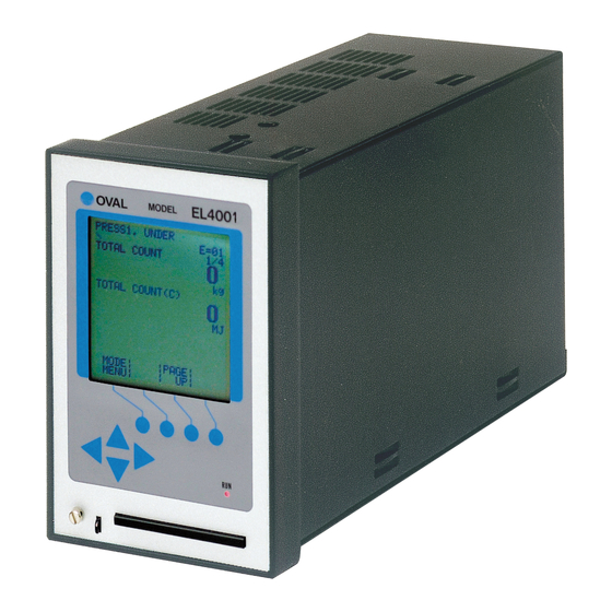
Temperature/pressure compensated
FLOW COMPUTER
(Gas service)
Model EL4121
This manual has been prepared to provide you with the information pertinent to the Temperature/
Pressure Compensated FLOW COMPUTER (Gas service).
With the proper application of the information and knowledge contained in this manual, you can
expect the best possible results over a long service life of this instrument. Keep this manual for
ready reference.
It is suggested that the instruction manuals for the companion pulse generator (flowmeter) and
receiving instrument be referred to at the same time.
1
Advertisement
Table of Contents

Related Manuals for Oval EL4121


Summary of Contents for Oval EL4121
- Page 1 Temperature/pressure compensated FLOW COMPUTER (Gas service) Model EL4121 This manual has been prepared to provide you with the information pertinent to the Temperature/ Pressure Compensated FLOW COMPUTER (Gas service). With the proper application of the information and knowledge contained in this manual, you can expect the best possible results over a long service life of this instrument.
-
Page 2: Table Of Contents
E - 882 - 4 - E TABLE OF CONTENTS ......................4 1. BEFORE YOU BEGIN 1.1 Confirming the Nameplate ..................... 4 1.2 Transportation Precautions ....................4 1.3 Storage Precautions ......................4 2. GENERAL ..........................5 2.1 Features ..........................5 2.2 Part Names .......................... - Page 3 E - 882 - 4 - E COMPANION VOLUME KEY OPERATION MANUAL Ins. No. E-880TM-E CONTENTS 1. KEY ARRANGEMENT ......................10 2. DISPLAY SCREEN ........................ 11 3. INITIAL CHECK ........................14 4. MODE SELECTION ......................18 5. RUN MODE SCREEN ......................23 6.
-
Page 4: Before You Begin
E - 882 - 4 - E 1. BEFORE YOU BEGIN Every OVAL product is thoroughly tested and inspected before shipment from our factory. When received, its appearance should be inspected for possible damage by rough handling during transit. First of all, thoroughly read the handling precautions described in this section. For topics other than those covered in this section, refer to the respective sections of this manual. -
Page 5: General
E - 882 - 4 - E 2. GENERAL Using the most advanced electronic tehcnologies, this digital instrument has been developed specifically to meet the most demanding gas flow measurement applications where accuracy is the prime requirement. In response to the gas flowrate, temperature, and pressure information arriving from the sensing terminal, such as a flowmeter, it calculates gas flow, reduced to the equivalent volume flow under standard conditions, and totalizes the flow. -
Page 6: Installation
E - 882 - 4 - E 3. INSTALLATION 3.1 Outline Dimensions All dimensions in millimeters Hold-down Fitting EL4001 MODEL TB 1 TB 2 TB 3 232.4 Fig. 3.1 Outline Dimensions 3.2 Installation 3.2.1 Installation Location Select an installation site where: (1) Mechanical vibration, shock and corrosive gases are Min.120 negligible. -
Page 7: Wiring
E - 882 - 4 - E 4. WIRING (See the "Wiring Guidelines" in the instruction manual of the companion pulse generator.) 4.1 Field Wiring Cables (1) Use electrostatically shielded, polyethylene insulated, vinyl sheathed control cables (CEVS, 1.25-2 mm, 2-conductor or 3-conductor), or equivalent, for input signal cables from the flowmeter. For output signal cables, use insulated vinyl sheathed cables (CVV, CVS ... -
Page 8: Product Code Explanation
E - 882 - 4 - E Table 4.2 Terminal Connections Label Description Label Description 3-wire generator SUP. SUP. +24VDC 2-wire generator (+) SIG. Press. in + 4 to 20mADC/ Flow in (−) Output sync with 1 to 5VDC − input signal (O.C.) (+)... -
Page 9: Internal Components And Functions
E - 882 - 4 - E 6. INTERNAL COMPONENTS AND FUNCTIONS 6.1 Front Panel 6.1.1 Display The display is a 128 × 128-dot multiple function display capable of showing the data, units of measure, error messages, and other information at the same time. (The display is backlighted.) 6.1.2 On-Screen Menu Items The units of measurement vary with configuration. -
Page 10: Error Messages
E - 882 - 4 - E 6.1.3 Error Messages When an erratic condition arises, an error message automatically appears on the display. (The informa- tion represented by error messages are listed on page 14.) If two or more concurrent errors are involved, individual messages will be scrolled at intervals of approxi- mately 3 seconds. -
Page 11: Calculation Formulas
E - 882 - 4 - E 7. CALCULATION FORMULAS 7.1 Implementation of Meter Error Correction (Total flow before correction) Q1 = a×Ip×(1 + E/100) ×ε : Meter s correction factor relative to temperature ε variation where Q : Total flow corrected for meter error [ l] ε... -
Page 12: Preparational Checks And Operation
E - 882 - 4 - E 8. PREPARATIONAL CHECKS AND OPERATION 8.1 Preparation Before Operation (1) Ensure that the instrument and related equipment are correctly installed and wired with no place left unfinished. WARNING: Make sure to see that the power terminals are connected to a power source of the rated voltage. -
Page 13: Troubleshooting
E - 882 - 4 - E 9. TROUBLESHOOTING Reminder: If internal trouble is suspected, seek our service at the nearest sales office or customer service representative in your area. Table 9.1 Problem Check Possible Causes Display is dead. 1. Inspect fuse. 1. -
Page 14: Error Messages
E - 882 - 4 - E 10. ERROR MESSAGES Table 10.1 List of Error Messages Error Message Description ADJUST DATA ERROR After adjusted, error on allowable range check A/D CONVERT ERROR A/D converter circuit error DENSITY CONVERT ERROR Density converter circuit error TEMP 1. -
Page 15: Overall Block Diagram
E - 882 - 4 - E 12. OVERALL BLOCK DIAGRAM... -
Page 16: General Specifications
E - 882 - 4 - E 13. GENERAL SPECIFICATIONS Table 13.1 Item Description Pulse Speed of Signal name Power to generator generator response 2-wire, 12VDC 3-wire 13.5VDC 50Hz − contact-closure pulse Allowable 2-wire, 12VDC 3-wire 13.5VDC − current voltage pulse Flow input 40mA app. - Page 17 E - 882 - 4 - E 2017.01 Revised 2008.08 Released All specifications are subject to change without notice for improvement. E-882-4-E (1)
Need help?
Do you have a question about the EL4121 and is the answer not in the manual?
Questions and answers