Table of Contents
Advertisement
E-216-5N-E
Ins. No.
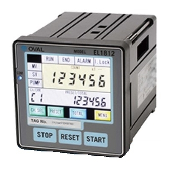
BATCH COUNTER
MODEL : EL1812
Every OVAL batch counter is fabricated, tested, inspected, and shipped from our factory under stringent quality
control. In order to maintain its design performance throughout its life, this manual offers the operator the
necessary installation, operation and maintenance information.
Be well familiar with these instructions before you place the counter in service and keep this manual at the field
location for ready reference.
Also refer to the instruction manual for the pulse generator (flowmeter) used.
1
Advertisement
Table of Contents

Related Manuals for Oval EL1812


Summary of Contents for Oval EL1812
- Page 1 BATCH COUNTER MODEL : EL1812 Every OVAL batch counter is fabricated, tested, inspected, and shipped from our factory under stringent quality control. In order to maintain its design performance throughout its life, this manual offers the operator the necessary installation, operation and maintenance information.
-
Page 2: Table Of Contents
E-216-5N-E CONTENTS 1. BEFORE YOU BEGIN ..................4 1.1 Confirmation of product name plate ............... 4 1.2 Transportation Considerations ............... 4 1.3 Storage Considerations ................. 4 2. GENERAL ......................5 2.1 Features and Functions ................. 5 3. PART NAMES ..................... 5 4. - Page 3 E-216-5N-E 9. CHANGE OF SETTING VALUE ................31 9.1 Parameter setting ..................... 31 9.2 Configuration of internal device ................ 35 9.3 Removal of inner assembly ................35 9.4 Installation of internal assembly ............... 36 9.4.1 How to assemble power supply / input board and output board ....36 9.4.2 How to assemble display unit ..............
-
Page 4: Before You Begin
Make yourself familiar with these instructions. As for other instructions, refer to respective sections. If you have something to inquire, contact the nearest OVAL authorized service station in your district. 1.1 Confirmation of product name plate... -
Page 5: General
E-216-5N-E 2. GENERAL Combined with a flowmeter and a shutoff valve, the batch counter passes a predetermined amount of the process fluid in batching operations. Built around a single chip microprocessor, this versatile, compact, and lightweight counter is designed for ease of operation. It saves time and effort in many processes, such as blending materials, dosing with additives, transferring materials from one tank to another, or shipping from an outlet, at chemical, food, paint plants or elsewhere where streamlined production lines are desired. -
Page 6: Installation
E-216-5N-E 4. INSTALLATION 4.1 Outline Dimensions Unit: mm 129.1 (17.1) Packing Fig. 4.1 Outline Dimensions 4.2 Installation 4.2.1 Installation Location (Indoor only) Unit: mm min.120 Choose to install in the place where: min.120 (1) Mechanical vibration, shock and corrosive gases least exist. -
Page 7: Wiring
E-216-5N-E 5. WIRING NOTE: See “WIRING” in the pulse generator instruction manual. 5.1 Cables for Field Wiring (1) For flowmeter input signal cable, electrostatically shielded, polyethylene insulated, vinyl-sheathed control cables (CEVS, 1.25 to 2mm , 2- or 3-conductor), or equivalent, must be used. For output signal cables, insulated, vinyl-sheathed cables (CVV, CVVS …... -
Page 8: External Connection Terminals
E-216-5N-E 5.4 External connection terminals Terminal block and D-SUB connector ● Input board side D-SUB connector Output board side ※1: D-SUB connector type 17P M3.5 Female 25P 17P M3.5 (※1) DBLC-J25SAF-23L6E Japan Aviation Electronics Industry, Limited − − 4-40-inch screw Terminal block Signal Description... -
Page 9: Flow Rate Input And Used Terminals
E-216-5N-E 5.5 Flow rate input and used terminals Contact-closure pulse / 2-wire voltage pulse 24VDC 2-wire type 3-line type open collector Signal type Open collector pulse 12VDC 2-wire type Current pulse 3-wire voltage pulse current pulse PG20, Coriolis flowmeter PA14, 15, 25 PG30, NPG60A Transmitter PG30S... -
Page 10: Example Of Hookup
ALTImass Type S Short-circuited when ALTImass Type U Function such as LED an interlock is not used light up when batching OVAL FLOWMETER CORIOLIS FLOWMETERS Terminal connection diagram completes is enabled (silk on left side of this device) OVAL owmeters, Coriolis owmeters, etc. - Page 11 E-216-5N-E Push button switch etc. (for fixing CH.) Selector1 Selector2 Selector4 Selector8 COM.1 GND2 Selector switch Rear surface of enclosure (for selecting CH.) D-SUB connector CH.1 CH.2 CH.3 CH.4 CH.5 CH.6 CH.7 CH.8 CH.9 CH.F Selector1 Selector2 Selector4 Selector8 Held by ON or OFF Each selection (contact a) (contact a) 200msec or more Fig.5.3 Example of Hookup (D-SUB connector)...
-
Page 12: Front Display Part And Batch Processing Part
E-216-5N-E 6. FRONT DISPLAY PART AND BATCH PROCESSING PART 6.1 Functions of front display part and batch processing part The display part has status indication lamps such as RUN and END. There are integration display, batch quantity setting value, and channel display part in the center of upper stage. There are operation indication lamps of valve and pump on the left side. -
Page 13: Block Diagram
E-216-5N-E 7. BLOCK DIAGRAM Fig. 7.1 Block ※1: To use the external operation input, it is necessary to prepare the connector of D-SUB25 pin by yourself NOTE: and connect the circuit for selecting a channel to D-SUB terminal on the rear surface of this machine. -
Page 14: Operation
E-216-5N-E 8. OPERATION 8.1 Preparation Before Operation (1) Make sure to see that the counter and associated equipment are correctly installed, connected and wired with no place left unfinished. CAUTION: Make sure to see that the power terminals are connected to a source of the rated voltage. Connecting an incorrect power voltage source may ruin the counter. -
Page 15: How To Set The Batch Setting Quantity
E-216-5N-E 8.4 How to set the batch setting quantity There are two methods for setting the batch setting quantity as shown below. (1) Select the memorized batch setting quantity from [CHANNEL SELECT] screen. CH.1 to 9 fixed batch setting quantity (2) Select an arbitrary batch setting quantity from [PRESET SETTING] screen. - Page 16 E-216-5N-E CH. F arbitrary batch setting quantity ● Carry out the setting following the flow shown below. Touch PRESET button on [BATCH PROCESSING] screen Shift to [PRESET SETTING] screen (*1) Clear the current value by touching CLR button and change the batch setting quantity from a numeric keypad (*1) If the channel selection is other than CF or cF, the screen does not shift...
-
Page 17: Batch Processing And Various Functions
E-216-5N-E 8.5 Batch processing and various functions (1) Usual operation At the same time when START button is pressed, the valve is opened to the predefined aperture. If a constant quantity of fluid flows (initial setting value = from point A to point B), the valve will be fully opened. If the measurement up to point C is completed, the valve will be automatically closed and kept to predefined aperture. - Page 18 E-216-5N-E (2) Temporary stop operation If you press STOP button, SV/MV output will be turned OFF and the operation will be temporarily stopped. PUMP output will be stopped after delay timer. If you press START button, the operation will be restarted. If the operation is temporarily stopped at upper limit flow rate, both of SV and MV will be turned ON at the restart and the flow rate will reach the upper limit flow rate (not becomes 2-stage open).
- Page 19 E-216-5N-E (3) Batch processing setting The batch processing enables five patterns of batch processing with four parameters shown below. ・Initial setting value ・Terminal setting value ・Batch setting quantity ・Forecasted overrun quantity Each pattern is shown below. Pattern 1 2-stage open 2-stage close Initial setting Final setting Forecasted overrun quantity...
- Page 20 E-216-5N-E Pattern 3 1-stage open 2-stage close If the conditions shown below are formed Initial setting Final setting Forecasted overrun quantity Initial setting Final setting Forecasted overrun quantity Initial setting Final setting Forecasted overrun quantity Operation (1) If you press START button, SV/MV output will be turned ON (2) If "cumulative total quantity"...
- Page 21 E-216-5N-E (4) Batch start unavailable conditions If the conditions shown below are formed, the batch processing cannot be started even if pressing the START button. Condition Response Total display part does not display 0 Press RESET button to reset the total flow value to 0 END lamp lights up Press RESET button to turn OFF the END lamp ALARM lamp lights up...
- Page 22 E-216-5N-E (7) External setting mode If the item 12 of parameter setting is set to 1, external channel selection and batch processing is enabled.( ※ In case of external setting, the channel display C at display part CH./ERR will become lower case (example: c1). Moreover, the channel selection on the front surface will be disabled.
- Page 23 E-216-5N-E (8) Batch cancellation If you want to cancel the batch operation in mid-flow, stop the operation temporarily, and then press "STOP" + "RESET". At this time, the total display part will be reset to 0. If you press STOP + RESET while the pump is operated, the operation will be stopped regardless of delay timer count value.
- Page 24 E-216-5N-E (13) Display of cumulative total flow unit The cumulative total flow unit can be displayed in the upper right of total display part (parameter item 16). The types of units to be displayed are shown below. 0: blank 1: mL 2: L 3: kL 4: m 5: g 6: kg 7: t 8: USG 9: barrel (The numbers are parameter setting numbers) Fig.
- Page 25 E-216-5N-E (15) Function for monitoring communications with LCD module This device can monitor the communication status of CPU and LCD module with LED on the front surface. ・Normal status: LED blinks 1Hz ・Abnormal status: LED blinks 4Hz (screen switching freezes, for example) * If an error is generated again after turning ON/OFF the power supply, the LCD may be broken.
- Page 26 E-216-5N-E (17) Batch history function You can check the history of recent five batches (expanded from MENU screen). The supplement of content on the screen is displayed on HELP screen. [BATCH RECODE] screen [BATCH RECODE HELP] screen "HELP" "BACK" Fig. 8.14 Batch history function (18) Alarm history function You can check the history of recent five alarms (expanded from MENU screen).
- Page 27 E-216-5N-E (20) Touch panel adjustment function Correct the sensitivity using the correction function of LCD module itself (expanded from SYSTEM screen). Carry out the operation following the instructions on the screen (touch the red circles in sequence). If "SAVED" screen is displayed finally, the correction is completed. The screen will automatically return to SYSTEM screen. If the correction is not completed within 15 seconds, "CANCELED"...
- Page 28 E-216-5N-E (23) Product information Model and system version are displayed (expanded from SYSTEM screen). [INFORMATION] screen [SYSTEM] screen "6.INFOR MATION" "BACK" Fig. 8.20 Product information...
-
Page 29: Alarm Processing
E-216-5N-E 8.6 Alarm processing There are eight types of alarms shown below. E1: pulse non-receipt alarm E2: overrun alarm E3: leak alarm E4: interlock alarm E5: emergency stop by RESET button E7: WDT reset alarm E8: electric power failure alarm E9: FeRAM alarm Buzzer sounds until STOP button is turned ON or during the setting time after the alarm is generated. The buzzer can be continuously sounded until the alarm is reset by setting parameter. - Page 30 E-216-5N-E E5: emergency stop by RESET button This alarm is generated when the temporary stop of batch processing is executed by pressing RESET button instead of STOP button. * Even if the STOP malfunctions the operation can be stopped, however, this is an alarm that indicates that restart is disabled while the STOP is not functioning.
-
Page 31: Change Of Setting Value
E-216-5N-E 9. CHANGE OF SETTING VALUE 9.1 Parameter setting The parameters can be set on [PARAMETER] screen. However, if a password is set, the screen will be expanded after the password is certified. Standard Item Range Remark value Channel 1 0 to 999999 count Sets the batch setting volume of channel 1 [C1]. - Page 32 E-216-5N-E How to set a parameter Touch "1.PARAMETER" on [MENU] screen to shift to [PARAMETER] screen. Display the parameters for five items each from C1 on the touch panel. Shift to the next parameter screen by pressing → button and shift to the previous parameter screen by pressing ←...
- Page 33 E-216-5N-E Password function ● Setting of password (at initial setting) Touch "4.SYSTEM" on [MENU] screen to shift to [SYSTEM] screen. Next, touch "1.PASSWORD". [INPUT PASSWORD] screen will be displayed. Input "111111 (default)". After the password is input, touch SET button to shift to [PASSWORD SETTING] screen. Change the password using a numeric keypad and CLR button.
- Page 34 E-216-5N-E Screen system Startup screen Top screen *After the top screen, the screen automatically shifts to BATCH PROCESSING screen 5. BATCH PROCESSING 5 -1 BATCH PROCESSING screen 5 -2 [CHANNEL SELECT] ■Sleep mode screen system 5 -3 [PRESET SETTING] Each screen [MENU] [Sleep mode] display screen 1.
-
Page 35: Configuration Of Internal Device
E-216-5N-E 9.2 Configuration of internal device This device has internal devices; "display unit", "power supply board", "input board", and "output board" as shown in Fig. 9.4. The display unit is configured with LCD module and CPU board. Power supply and input board are configured by connector connection. -
Page 36: Installation Of Internal Assembly
E-216-5N-E CPU board Pull out the output board module LCD module/ Installation CPU board screw (x8) Pull out power Spacer (x4) Harness supply/input board Fig.9.7 Fig.9.8 (3) Pull out power supply/input board and output (4) LCD module/CPU board can be separated into LCD board from CPU board. -
Page 37: Change Of Setting On Input Board And Cpu Board
E-216-5N-E 9.5 Change of setting on input board and CPU board Switches on the input board and CPU board are located at the positions shown below. Input board SW1 Input board SW2 CPU board SW1 CPU board SW2 Fig. 9.10 The input board SW1 sets the power supply voltage of flowmeter transmitter and the input board SW2 sets the type of input pulse from flowmeter (when you purchase the product, the setting is implemented depending on the preliminarily specified type code). -
Page 38: Troubleshooting
E-216-5N-E 10. TROUBLESHOOTING 10.1 Inspection Items NOTE: If trouble is found to be internal, check on the problem according to the table below and seek our service. Problem What to check Possible causes 1. Inspect fuse. 1. Breaking of fuse ( ⇒ refer to section 10.2) 2. -
Page 39: Q&A About Counter Behavior In Standby Mod
E-216-5N-E 10.2 Q&A about Counter Behavior in Standby Mod Questions Answers ・Counted. The accumulated total is also counted. 1. What if a pulse train arrives ・SV and MV valve signals remain inoperative (remain in the OFF). in standby mode? ・ If a leak error is set, a leak error is generated when a pulse of setting value or more is input. -
Page 40: General Specifications
12V DC 2-wire PG30S 13.5VDC "0": 4mADC current pulse Input load resistance: 510Ω PA14/15/25 "1": 20mADC 24V DC 2-wire ULTRA OVAL 24VDC "0": 4mADC current pulse NPG60A (E) Input load resistance: 250Ω Form "a" contact Start Form "a" contact Reset Contact signal/Open collector signal Form "b"... -
Page 41: Product Symbol
E-216-5N-E 12. PRODUCT SYMBOL Output item 2 Always N Always N Output item 1 Always NN Input signal Always N Power supply Version code Model Characteristic ① ② ③ ④ ⑤ ⑥ − ⑧ ⑨ − ⑪ ⑫ ⑬ ⑭ ⑮... - Page 42 E-216-5N-E 2018. 04 Revised△ 2017. 04 Released All specifications are subject to change without notice for improvement. E-216-5N-E (1)
Need help?
Do you have a question about the EL1812 and is the answer not in the manual?
Questions and answers