
Subscribe to Our Youtube Channel
Related Manuals for SeaLevel Ultra 530.LPCIe


Summary of Contents for SeaLevel Ultra 530.LPCIe
- Page 1 Ultra 530.LPCIe User Manual | 7106e © Sealevel Systems, Inc. 7106e Manual | SL9268 11/2022...
-
Page 2: Table Of Contents
APPENDIX D – ASYNCHRONOUS COMMUNICATIONS .................. 25 APPENDIX E – GROUND LOOP PHENOMENON ....................26 APPENDIX F – MECHANICAL DRAWING ......................27 APPENDIX G – COMPLIANCE NOTICES ......................28 WARRANTY ................................ 29 © Sealevel Systems, Inc. 7106e Manual | SL9268 11/2022... -
Page 3: Introduction
Windows 7/8.1/10 and Linux operating systems. The Ultra 530.LPCIe ships with a Low Profile PCIe bracket that will only work in a Low Profile PCIe slot. If you need a standard size PCIe bracket, please order Item# 7106eS. The product is RoHS compliant and meets the requirements of RoHS (2011/65/EU) directive. -
Page 4: Before You Get Started
Before You Get Started What’s Included The Ultra 530.LPCIe is shipped with the following items. If any of these items are missing or damaged, please contact Sealevel for replacement. Ultra 530.LPCIe Adapter • Advisory Conventions Warning The highest level of importance used to stress a condition where damage could result to the product, or the user could suffer serious injury. - Page 5 Length. Convert any DB25 Female RS-530 Async Adapter to the Sealevel RS-422 DB9 Male pinout. Useful in situations where cabling is already in place for the Sealevel DB9 implementation of RS-422. DB25 Female to DB37 Male Cable (Part Number CA107) DB25 Female (RS-530) to DB37 Male (RS-449 DTE) Cable, 10- inch Length.
- Page 6 DB9 serial connection, including RS-232. The TB05 includes holes for board or panel mounting. The TB05 is designed to connect directly to Sealevel DB9 serial cards or any cable with a DB9M connector. © Sealevel Systems, Inc.
-
Page 7: Card Setup
Only one driver may be active at a time and the other driver(s) must be tri- stated. The output modem control signal Data Terminal Ready (DTR) is used to control the state of the driver automatically. © Sealevel Systems, Inc. 7106e Manual | SL9268 11/2022... - Page 8 Enables RS-422/RS-485 RD+ 510 ohm pull-up to 5V (biasing) Enables RS-422/RS-485 RD– 510 ohm pull-down to GND (biasing) Enables RS-485 two-wire mode, connecting TX– to RX– Enables RS-485 two-wire mode, connecting TX+ to RX+ © Sealevel Systems, Inc. 7106e Manual | SL9268 11/2022...
- Page 9 0 to 15 bit-time delay after the end of the last stop-bit of the last transmitted character. This delay controls when to automatically disable the RS-485 transmitter. This delay may be useful in long-cable networks. © Sealevel Systems, Inc. 7106e Manual | SL9268 11/2022...
-
Page 10: Software Installation
Windows and Linux operating systems. Where to Get Sealevel Software The current versions of Sealevel software packages can be obtained from the Sealevel website (see following instructions). If you already have the Sealevel software, proceed to the Windows or Linux installation section. - Page 11 Windows Installation Do not connect the hardware until the software has been successfully installed. To install Sealevel software, you must log in as an administrator or have administrator privileges in Window Guided Software Installation. . 1. Type the part number for your adapter in the text box and press the ‘Enter’ key or click on the drop box to scroll from the listing to select your product.
- Page 12 6. If prompted, reboot your computer for changes to take effect. Upgrading to the current SeaCOM driver 1. Download the current driver using the Instructions from the Where to Get Sealevel Software section above. Please take note of the destination directory for download.
-
Page 13: Hardware Installation
&LPT)’ and the COM assignment will be included with the associated COM number in parentheses. Your system will assign the next available COM number, which will vary by computer (COM8 is shown in this example). © Sealevel Systems, Inc. 7106e Manual | SL9268 11/2022... - Page 14 Locate the ULTRA 530.LPCIe device in the listing. Right click on the entry for the ‘ULTRA 530.LPCIe’ device and click ‘Uninstall’ Confirm that you want to uninstall the device by clicking the ‘OK’ button. This will remove the hardware, COM ports and all registry entries from your computer. Keep the device installed.
-
Page 15: Technical Description
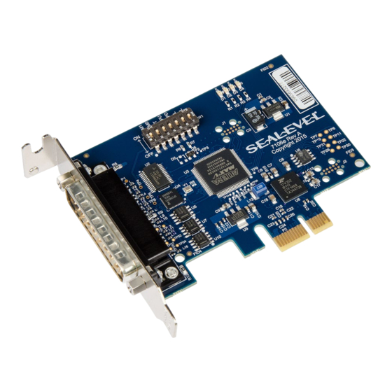
Technical Description The Sealevel Systems 7106e provides a PCIe interface adapter with 1 asynchronous serial port providing a versatile, field selectable RS-232 interface for modems, printers, and plotters, as well as RS-422/485/530 for industrial automation and control applications. The 7106e provides a UART with a 256 byte TX and RX FIFOs, providing programmable baud rates, data format, and interrupt control. -
Page 16: Technical Specifications
At 25º C ambient Manufacturing All Sealevel Systems Printed Circuit boards are built to UL 94V0 rating and are 100% electrically tested. These printed circuit boards are solder mask over bare copper or solder mask over tin nickel. Power Consumption Typical Power Draw 2.5W... -
Page 17: Appendix A - Troubleshooting
Appendix A – Troubleshooting Once you have confirmed that the serial adapter COM ports are listed in Device Manager, use the Sealevel WinSSD utility to verify communications. Detailed help is included in the WinSSD utility. Please set the adapters Electrical Interface for either RS-232 or RS-422. - Page 18 This will first open the COM port. From this tab the port can also be closed (See image below). Click the ‘Settings’ button to open the COM Port Properties dialog box. This will allow the Port Settings to be altered. © Sealevel Systems, Inc. 7106e Manual | SL9268 11/2022...
- Page 19 Change your parameters to 9600 bits per second, 8 data bits, no parity, 1 stop bit, and no flow control, as pictured below. Click ‘Apply’ and ‘OK’. © Sealevel Systems, Inc. 7106e Manual | SL9268 11/2022...
- Page 20 In the main WinSSD window, click on the ‘BERT’ tab (Bit Error Rate test). Click on the ‘Start’ button. © Sealevel Systems, Inc. 7106e Manual | SL9268 11/2022...
- Page 21 If these steps do not solve your problem, please call Sealevel Systems’ Technical Support, (864) 843-4343. Our technical support is free and available from 8:00 A.M.- 5:00 P.M. Eastern Time Monday through Friday.
-
Page 22: Appendix B - Handling Instructions
10. Keep work area free of non-conductive materials such as ordinary plastic assembly aids and Styrofoam. 11. Use field service tools such as cutters, screwdrivers, and vacuum cleaners that are conductive. © Sealevel Systems, Inc. 7106e Manual | SL9268 11/2022... -
Page 23: Appendix C - Electrical Interface
0 (space) and -12 volts (-3 to -10 volts) denote a binary 1 (mark). The RS-232 and the EIA/TIA-574 specification define two types of interface circuits Data Terminal Equipment (DTE) and Data Circuit-Terminating Equipment (DCE). The Sealevel Systems Adapter is a DTE interface. RS-422 The RS-422 specification defines the electrical characteristics of balanced voltage digital interface circuits. - Page 24 The RS-530 specification defines two types of interface circuits, Data Terminal Equipment (DTE) and Data Circuit-Terminating Equipment (DCE). The Sealevel Systems adapter is a DTE interface. © Sealevel Systems, Inc.
-
Page 25: Appendix D - Asynchronous Communications
The communication parameters are baud rate, parity, number of data bits per character, and stop bits (i.e.,9600,N,8,1). © Sealevel Systems, Inc. 7106e Manual | SL9268 11/2022... -
Page 26: Appendix E - Ground Loop Phenomenon
DC to DC converter circuit or in the opto- isolator circuit. This condition will cause data errors and possibly destruction of the receiver circuit DATA+ DATA- Isolated Isolated Adapter Ground Adapter Isolation Barrier © Sealevel Systems, Inc. 7106e Manual | SL9268 11/2022... -
Page 27: Appendix F - Mechanical Drawing
Appendix F – Mechanical Drawing © Sealevel Systems, Inc. 7106e Manual | SL9268 11/2022... -
Page 28: Appendix G - Compliance Notices
Always use cabling provided with this product if possible. If no cable is provided or if an alternate cable is required, use high quality shielded cabling to maintain compliance with FCC/EMC directives. © Sealevel Systems, Inc. 7106e Manual | SL9268 11/2022... -
Page 29: Warranty
Sealevel's commitment to providing the best I/O solutions is reflected in the Lifetime Warranty that is standard on all Sealevel manufactured I/O products. We are able to offer this warranty due to our control of manufacturing quality and the historically high reliability of our products in the field. Sealevel products are designed and manufactured at its Liberty, South Carolina facility, allowing direct control over product development, production, burn-in and testing.
Need help?
Do you have a question about the Ultra 530.LPCIe and is the answer not in the manual?
Questions and answers