Advertisement
Quick Links
Advertisement

Subscribe to Our Youtube Channel
Related Manuals for SeaLevel eI/O-110 Series


Summary of Contents for SeaLevel eI/O-110 Series
- Page 1 Sealevel Systems, Inc. Sealevel.com Phone 864.843.4343...
- Page 2 SeaMAX Overview ..........................17 Communicating Via Modbus ........................ 17 SeaMAX Software Installation ....................... 18 Driver Installation from the Sealevel Disk using „AutoRun‟............... 18 Instructions for Downloaded Software Installation ................20 Upgrading to the current SeaIO driver (SeaMAX) ................20 MaxSSD Configuration & Diagnostics Utility ..................21 Troubleshooting Ethernet eI/O Modules .....................
- Page 3 Warranty ..............................37 Warranty Policy ............................37 Non-Warranty Repair/Retest ........................ 37 How to obtain an RMA (Return Merchandise Authorization) ............. 37 Trademarks ............................37 ©Sealevel Systems, Inc. eI/O Manual SL9049 - 03/2011...
- Page 4 All eI/O modules are shipped with the following items. If any of these items is missing or damaged please contact Sealevel for a replacement. eI/O Data Acquisition Module Sealevel SeaMAX Software CD Do not connect the I/O module to the host until the software is installed.
- Page 5 Sealevel eI/O™ modules offer powerful data acquisition solutions that are perfect for a wide range of applications and environments with easy interfacing to computers, controllers, and PLCs. eI/O modules are available in various digital, analog, and serial I/O configurations. Each eI/O model is designed for maximum flexibility and easy field wiring.
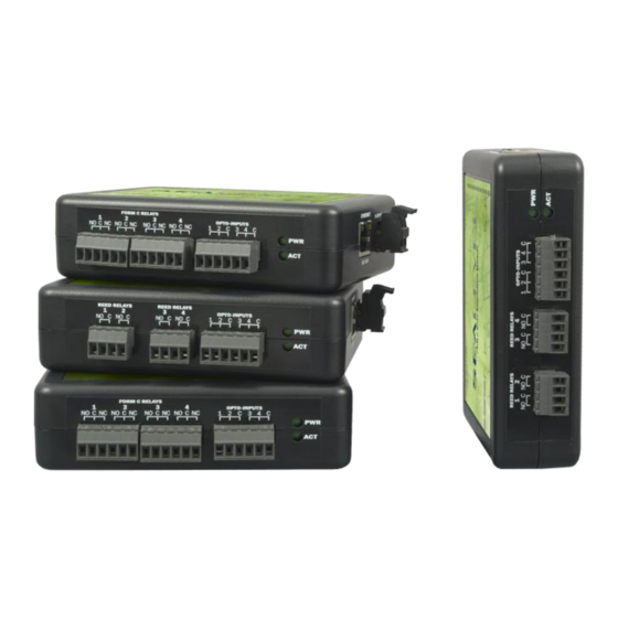
- Page 6 120PoE – 4 Optically Isolated Inputs/4 Form C Outputs eI/O 130PoE – 4 Optically Isolated Inputs eI/O 140PoE – 4 Form A Reed Relay Outputs eI/O 150PoE – 4 Form C Relay Outputs ©Sealevel Systems, Inc. eI/O Manual SL9049 - 03/2011...
- Page 7 Depending on the interface type, your eI/O module may include additional accessories. Included accessories are listed below. All items can be purchased from our website (www.sealevel.com) by calling our sales team at (864) 843-4343. CAT5 Patch Cable (Part# CA246) Standard 7' CAT5 UTP Patch Cable (RJ45).
- Page 8 240VAC to 12VDC @ 500mA Wall Mount Power Supply (Part# TR106) The TR106 is a wall wart style power supply for the United Kingdom, Hong Kong, Singapore, and Malaysia. The TR106 is rated for 240VAC input and 12VDC output at 500mA. ©Sealevel Systems, Inc. eI/O Manual SL9049 - 03/2011...
- Page 9 CAT5 Patch Cable, 10' in Length (Part# CA247) 10‟ Blue Ethernet Patch Cable. Can be used to connect eI/O Ethernet modules to a hub or switch. ©Sealevel Systems, Inc. eI/O Manual SL9049 - 03/2011...
- Page 10 Status LEDs are also included on the front of all eI/O modules to indicate the following information: Power (Green) – Lights when power is applied to the module. Act (Green) – Light blinks when Modbus/TCP activity is present or when new firmware is being downloaded. ©Sealevel Systems, Inc. eI/O Manual SL9049 - 03/2011...
- Page 11 2500VAC RMS / 3500VDC Input Resistance 6.2K Ohms in series Outputs Type 4 SPST Form A Form A Reed Relays Power DC 30W / AC 10VA Max. Contact Voltage 60VDC max. Contact Current 500mA max. ©Sealevel Systems, Inc. eI/O Manual SL9049 - 03/2011...
- Page 12 DC 240W / AC 1200 VA Contact Voltage 60VDC / 250VAC max. (5VDC min.) Contact Current (DC) <30 VDC @ 5A max. >30 VDC @ 700mA max. (100mA min.) Contact Current (AC) 6A max. ©Sealevel Systems, Inc. eI/O Manual SL9049 - 03/2011...
- Page 13 Each pair of inputs shares a common and field wiring is simplified via 3.5mm field removable terminal blocks. Inputs Type 4 non-polarized optically isolated inputs Voltage Range 5-30VDC Isolation 2500VAC RMS / 3500VDC Input Resistance 6.2K Ohms in series ©Sealevel Systems, Inc. eI/O Manual SL9049 - 03/2011...
- Page 14 14-22 AWG wiring allow reliable connection to real world I/O. Outputs Type 4 SPST Form A Form A Reed Relays Power DC 30W / AC 10VA Max. Contact Voltage 60VDC max. Contact Current 500mA max. ©Sealevel Systems, Inc. eI/O Manual SL9049 - 03/2011...
- Page 15 DC 240W / AC 1200 VA Contact Voltage 60VDC / 250VAC max. (5VDC min.) Contact Current (DC) <30 VDC @ 5A max. >30 VDC @ 700mA max. (100mA min.) Contact Current (AC) 6A max. ©Sealevel Systems, Inc. eI/O Manual SL9049 - 03/2011...
- Page 16 9-30VDC source using the screw terminals on the side of the unit. Sealevel offers several power supply choices to make connection easy (see the Accessories chapter at the end of this document). The eI/O PoE units are Class 0 (IEEE 802.3af-2003) Power over Ethernet devices. This allows power and data to be transferred over a single CAT5 cable and eliminates the need for an external power supply.
- Page 17 The SeaMAX Suite is a collection of configuration/diagnostic utilities and software libraries that enable rapid application development. The SeaMAX API, included in the SeaMAX Suite, provides a common API for Sealevel eI/O and SeaDAC data acquisition modules. SeaMAX is designed to simplify application development by requiring little knowledge of the underlying communication protocols of these devices and replacing low-level programming.
- Page 18 Proceed with installing the SeaMAX Software Suite using the software disk that was included with your Sealevel I/O module. Software drivers are also available on the product webpage on the Sealevel website at www.sealevel.com. To install Sealevel Systems software, you must log in as an administrator or have administrator privileges in Windows.
- Page 19 Next follow the information presented on the screens that follow. Once the installation is complete, close the disk installation window. 11. Refer to the Physical Installation section to connect and install your adapter. ©Sealevel Systems, Inc. eI/O Manual SL9049 - 03/2011...
- Page 20 Windows Vista and newer operating systems, it will be found in the „Programs and Features‟ list. 3. Navigate to the Device Manager and remove the Sealevel digital I/O adapter by right clicking on the line item under „SeaI/O Device‟ and choosing „Uninstall‟.
- Page 21 Windows 2000, XP, Vista and Windows 7. When you run the MaxSSD utility (Start All Programs Sealevel Systems SeaMAX MaxSSD Configuration Utility) it will default to the “Host PC Configuration” tab. This tab allows the user to choose the initial communication settings for the connected I/O device.
- Page 22 Click the “Get SeaIO Module Settings” button. After a short delay, the information for that I/O module should be displayed. If no information appears, verify that the host settings are correct and make changes if necessary. ©Sealevel Systems, Inc. eI/O Manual SL9049 - 03/2011...
- Page 23 After a successful Get operation, additional tabs may be displayed in MaxSSD, depending on the device model found. These tabs display device I/O and allow easy configuration for all SeaMAX supported devices. ©Sealevel Systems, Inc. eI/O Manual SL9049 - 03/2011...
- Page 24 The „Digital IO‟ tab of MaxSSD is displayed when using Sealevel I/O devices featuring discrete inputs and outputs. It displays the device‟s current input and/or output status in an intuitive and usable manner. When banks of inputs are displayed, the status LEDs update on each of the banks automatically.
- Page 25 6. Refer to the Troubleshooting Ethernet eI/O Modules section on the following page for additional steps regarding eI/O modules. 7. If these steps do not solve your problem, please contact Sealevel Technical Support. Our technical support is free and available from 8:00am – 5:00 pm EST, Monday through Friday.
- Page 26 PC on the same subnet. Adjust the eI/O module‟s IP address and Netmask using the Ethernet Config utility (Start All Programs Sealevel Systems SeaMAX Ethernet Configuration Tool) installed with SeaMAX. Then restore the PC‟s network settings.
- Page 27 The module list should refresh, indicating that your changes were successful. Start MaxSSD (Start All Programs Sealevel Systems SeaMAX MaxSSD Configuration Utility) and choose the correct IP address to communicate with the eI/O module. Ensure a successful Get operation (refer to the MaxSSD section of this manual for more information).
- Page 28 Contact your network administrator if you are unsure of the proper network settings to choose. If a DHCP server is available, select the “Enable DHCP Configuration” checkbox. Otherwise, complete the network settings and click the “Recover Module” button to complete the configuration changes. ©Sealevel Systems, Inc. eI/O Manual SL9049 - 03/2011...
- Page 29 (without the quotation marks and hit enter. You will then see a command prompt (ie. c:\documents and settings\name>). Once you are at the command prompt, browse to your SeaMAX folder. The default location is “C:\Program Files\Sealevel Systems\SeaMAX\”. Your *.hex file will need to be saved to this folder as well.
- Page 30 The above should only be performed if you (1) really feel the update is required and (2) you feel confident in your ability to perform the update. Once the firmware has been erased, you must either be able to re-program it locally or send it back to SeaLevel Systems, Inc. for reprogramming.
- Page 31 Exercise caution when performing a firemware upgrade to ensure that the process does not get interrupted until the process completes. Once the firmware has been erased, you must either be able to re-program it locally or send it back to Sealevel Systems, Inc. for reprogramming.
- Page 32 Form C Relay outputs are arranged such that each relay has a common. The NC and NO contacts of two relays along with the commons are brought out via a six-position removable screw terminal. ©Sealevel Systems, Inc. eI/O Manual SL9049 - 03/2011...
- Page 33 (Mode B) and mixed DC and data (Mode A) Power over Ethernet 802.3af-2003 configurations are acceptable for the eI/O. The eI/O PoE series modules are class 0 power over Ethernet devices. Signal PoE Mode A PoE Mode B TX+/DC+ TX-/DC+ RX+/DC- RX-/DC- ©Sealevel Systems, Inc. eI/O Manual SL9049 - 03/2011...
- Page 34 The units ship with four rubber feet that help prevent the devices from sliding due to vibration and help protect surfaces from scratches. The small enclosures take up very little space. ©Sealevel Systems, Inc. eI/O Manual SL9049 - 03/2011...
- Page 35 Keep work area free of non-conductive materials such as ordinary plastic assembly aids and Styrofoam. Use field service tools such as cutters, screwdrivers, and vacuum cleaners which are conductive. Always place drives and boards PCB-assembly-side down on the foam. ©Sealevel Systems, Inc. eI/O Manual SL9049 - 03/2011...
- Page 36 When calling for technical assistance, please have the device installed and ready to run diagnostics. If possible, have your user manual and current settings ready. The Sealevel website is an excellent resource located at www.sealevel.com. The most current software updates and user manuals are available via our homepage by clicking on the 'Drivers' or 'Manuals' links located under „Technical Support.‟...
- Page 37 In the event of failure, Sealevel will repair or replace the product at Sealevel's sole discretion. Failures resulting from misapplication or misuse of the Product, failure to adhere to any specifications or instructions, or failure resulting from neglect, abuse, accidents, or acts of nature are not covered under this warranty.
Need help?
Do you have a question about the eI/O-110 Series and is the answer not in the manual?
Questions and answers