Table of Contents
Advertisement
Advertisement
Table of Contents

Related Manuals for Nice UDL 2


Summary of Contents for Nice UDL 2
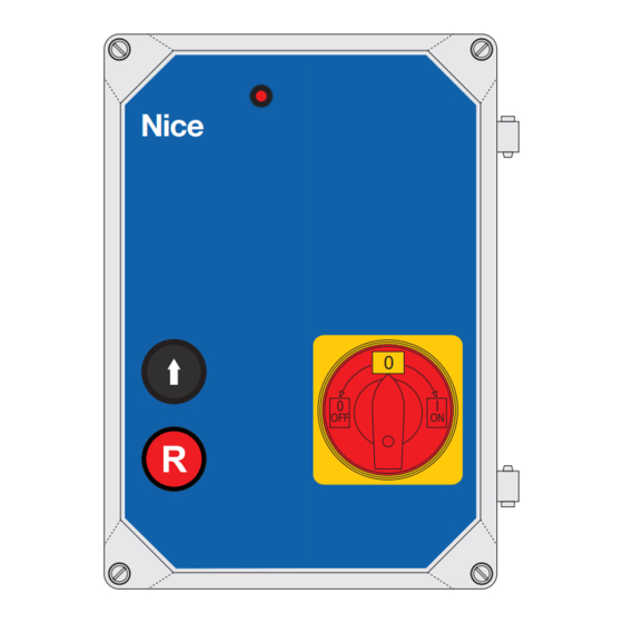
- Page 1 UDL 2 UDL 2 Control unit for loading ramps with telescopic or rotary side panel Nice Instructions and information for installation and use The entire instruction manual is made up of instructions for use regarding the gearmotor and its control unit.
-
Page 2: Table Of Contents
TABLE OF CONTENTS GENERAL RULES OF SAFETY ..................3 PREPARATION OF THE INSTALLATION .................3 FERRITE CONNECTION ....................4 CONTROL ELEMENT CONNECTION ................4 DESCRIPTION OF OPERATION ..................6 OPERATION WITHOUT CUSTOMISATION MODULE ..........6-7 OPERATION WITH CUSTOMISATION MODULE ............8-9 TERMINAL WIRING DIAGRAM ..................11 BOARD OVERVIEW ......................12 KEY ..........................12 TRANSPORT / STORAGE / DISPOSAL .................13... -
Page 3: General Rules Of Safety
PREPARATION FOR INSTALLATION Description and use UDL 2 is a unit for controlling loading ramps with telescopic or rotary side panel and for controlling a shelter for vehicles with additional module. The control unit is set with the program appropriate for the selected type of ramp. - Page 4 A 16A EEC plug is connected to terminals Y1a/L1,L2,L3, Y1c/N Y4/1,2 (J14) terminal. and PE. The network is to be connected to UDL 2 with a three-phase main Test program [tSt] switch, as required by the EN 1398 standard. In programming mode it is possible to control the corresponding valve (1-3) or enable the ON/OFF motor function by pressing the button on the cover.
-
Page 5: Ferrite Connection
Ferrite connection to the motor connection cable (fig. 6-11) It is necessary to connect a FERRITE to the motor connection cable. To do this, insert three black wires in the ferrite as shown in figure, wrap them around the ferrite once and make the connection. (Now there are 6 wires in the ferrite!) Pass the PE cable next to the ferrite, WITHOUT crossing it! Connect the wires to the U V W and PE motor terminals. -
Page 6: Description Of Operation
DESCRIPTION OF OPERATION OPERATION WITHOUT CUSTOMISATION MODULE Control of the ramp with telescopic side panel and automatic lowering [P21/P23/P31] BASIC PROGRAMMING The loading ramp is raised in deadman mode with the button built It is necessary to set and store the most important parameters into the cover (Ramp UP). -
Page 7: Operation With Customisation Module
Now Lr0 appears on the display. OPERATION WITH CUSTOMISATION MODULE Lr is the ramp lowering time when the AUTORETURN button is enabled in 00E status. The basic time set is 5 seconds. By pressing the Ramp UP button repeatedly, now it is possible to CUSTOMISATION MODULE [PEEP] CONNECTION select a number between 1 and 9. - Page 8 EXTERNAL TRAFFIC LIGHTS connection - [option 4 (o1)] - fig. 16 Connection - vehicle detector The red traffic lights are connected to terminal Y3/12 (J24), the green traffic lights to terminal Y3/13 (J24) and the common N Vehicle conductor to terminal Y3/11 (J24). detector (closing Connection - external RED /...
- Page 9 K4 module terminal 4.6 (J3) - is connected to Connection - 6.3 HV fuse for terminals Y6/7.8 (J25 of the UDL 2 (ramp enabling) if you use the docklight/internal-external traffic UST1 or UST1K-1.1kW terminal x3/4.6. With these two connections...
- Page 10 UDL 2 WIRING DIAGRAM Hydraulic motor Fuse Door enabling UST1-MB Relay 4 Loading terminal ramp lighting X3 (1, 2) Relay 3 External traffic lights Vehicle detector Relay 2 Internal traffic lights Wheel wedge Relay 1 Forced lowering Valvole 3 (safety enclosure)
-
Page 11: Key
fuse 6.3 HV fuse 6.3 HV fuse 6.3 HV fuse 6.3 HV transformer network terminal block terminal block for main switch terminal block for main switch motor screw terminal screw terminal of control devices J30 (Y3/6.7) loading ramp lighting connection J9 (Y3/8-10) external traffic lights connection J24 (Y3/11-12) internal traffic lights connection hydraulic valve screw terminal... - Page 12 UDL 2 BOARD OVERVIEW Main switch ECC network input Hydraulic motor Main switch Fuse 6,3 HV Loading ramp Door enabling lighting External traffic lights Internal traffic lights Input protection device Slot for Shelter module Hydraulic valve 3 Hydraulic valve 2...
-
Page 13: Transport / Storage / Disposal
• All of the technical characteristics indicated refer to a temperature of 20°C (± 5°C). • Nice reserves the right to introduce all modifications to the product it deems necessary at any time, however keeping the functions and intended use unaltered. -
Page 14: Declaration Of Conformity
Note - The content of this declaration corresponds to the declaration at the last available version of the document filed in the offices of Nice S.p.A. prior to the printing of this manual. This text has been adapted to meet editorial requirements. A copy of the original declaration may be requested from Nice S.p.a.
Need help?
Do you have a question about the UDL 2 and is the answer not in the manual?
Questions and answers
Добрый день! На панели блока управления мигает диод сервисного обслуживания! В инструкции нет способа сброса ! Помогите!
To reset the service indicator light on the Nice UDL 2 control panel, contact customer service. The service LED begins to blink slowly after 1000 cycles or in case of other faults, and it stays on continuously when the dock leveler is in floating (operating) mode.
This answer is automatically generated