Table of Contents
Advertisement
Available languages
Available languages
Quick Links
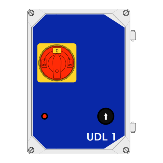
UDL 1
Control unit for loading ramps
0
0
I
OFF
ON
UDL 1
IT -
Istruzioni e indicazioni d'installazione e uso
L'intero manuale d'istruzioni è composto delle istruzioni per l'uso rispettivamente del motoriduttore e della relativa centrale di comando.
EN -
Instructions and information for installation and use
The entire instruction manual is made up of instructions for use regarding the gearmotor and its control unit.
FR -
Instructions et indications d'installation et d'utilisation
L'ensemble du manuel d'instructions comprend les instructions pour utiliser respectivement le motoréducteur et sa centrale de commande.
ES -
Instrucciones e indicaciones para la instalación y el uso
El manual de instrucciones está compuesto por las instrucciones de uso del motorreductor y de la central de mando relativa.
DE -
Anweisungen und Hinweise für Installation und Bedienung
Die Gesamt-Bedienungsanleitung besteht aus der BA des Antriebes und der dazugehörigen BA der Steuerung.
PL -
Instrukcja i wskazówki na temat instalacji i eksploatacji
Cała instrukcja obsługi zawiera instrukcje dotyczące obsługi odpowiednio motoreduktora oraz właściwej centrali sterowniczej.
NL -
Instructies en aanwijzingen voor de installatie en het gebruik
De volledige instructiehandleiding bestaat uit de gebruiksaanwijzingen voor het gebruik van respectievelijk de reductiemotor en
van de bijbehorende bedieningscentrale
Advertisement
Table of Contents

Related Manuals for Nice UDL 1


Summary of Contents for Nice UDL 1
- Page 1 UDL 1 Control unit for loading ramps UDL 1 IT - Istruzioni e indicazioni d’installazione e uso L‘intero manuale d‘istruzioni è composto delle istruzioni per l‘uso rispettivamente del motoriduttore e della relativa centrale di comando. EN - Instructions and information for installation and use The entire instruction manual is made up of instructions for use regarding the gearmotor and its control unit.
- Page 3 ACCESSORI Descrizione e utilizzo DICHIARAZIONE DI CONFORMITÀ L' UDL 1 è una centrale di comando per rampe di carico con un gruppo idraulico a 1 valvola (24V/DC). Per azionare la rampa si preme il tasto SU della centrale di comando.
- Page 4 Collegamento rete UDL 1 - (fig. 1) Collegamento sensore Ai morsetti L1, L2, L3 e al morsetto PE collegare una spina CEE da bloccaggio porta 16A. Il collegamento di rete all'UDL 1 va effettuato tramite un interruttore principale trifase. (EN 1398) Collegamento interruttore principale 24V+ Sens Controllo di fase Le 3 fasi della linea di rete sono controllate dall'UDL 1.
- Page 5 PANORAMICA SCHEDA UDL 1 Fusibile 2 A T Commutazione sensore PNP/NPN Interruttore coperchio Commutatore 230V/400V Sensore bloccaggio Trasformatore porta Valvola idraulica Coperchio led o cavallotto cortocircuito Relè 2 Relè-Valvola Fusibile 3x6,3A-T Interruttore principale-OUT Relè 1 Contatto protetto Gruppo idraulico Interruttore principale-IN...
- Page 6 SCHEMA DI COLLEGAMENTO UDL1 4 – Italiano...
- Page 7 LEGENDA fusibile 6,3A T fusibile 6,3A T fusibile 6,3A T trasformatore fusibile 2A T REL1 contatto protetto gruppo idraulico relè valvola REL2 relè valvola commutazione sensore (PNP/NPN) interruttore coperchio morsettiera rete morsetto PE morsettiera motore sensore bloccaggio ponte porta commutatore 230V/400V morsetto a vite interruttore principale OUT morsetto a vite interruttore principale IN morsetto a vite valvola idraulica...
- Page 8 • Tutte le caratteristiche tecniche indicate si riferiscono a una temperatura di 20°C (± 5°C). • Nice si riserva il diritto di apportare, in qualunque momento, tutte le modifiche al prodotto che ritiene necessarie, mantenendo comunque inalterate la funzionalità e la destinazione d'uso...
- Page 9 Dichiarazione in accordo alle Direttive: 2004/108/CE (EMC); 2006/42/CE (MD) allegato II, parte B Nota - Il contenuto di questa dichiarazione corrisponde a quanto dichiarato nel documento ufficiale depositato presso la sede di Nice S.p.a., e in particolare, alla sua ultima revisione disponibile prima della stampa di questo manuale. Il testo qui presente è stato riadattato per motivi editoriali.
-
Page 11: Table Of Contents
PREPARATION FOR INSTALLATION TECHNICAL ASSISTANCE/SPARE PARTS/ ACCESSORIES Description and use DECLARATION OF CONFORMITY The UDL 1 is a control unit for loading ramps with a 1-valve hydraulic unit (24V/DC). To activate the ramp, press the UP button on the control unit. Any other use is considered improper! The manufacturer declines all responsibility whatsoever for damages caused by improper use of the various system devices not compliant with what is indicated in this manual. -
Page 12: Control And Connection Elements
Connection of the door locking sensor (fig.4) CONTROL and CONNECTION ELEMENTS The terminal block J6 (24V+, sens and GND) can be connected with a door locking sensor. Network - UDL 1 connection - (fig. 1) Connection of the door locking Connect a 16A CEE plug to terminals L1, L2, L3 and PE. The network connection to UDL 1 is to be made with a three-phase sensor main switch. (EN 1398). -
Page 13: Udl 1 Board Overview
UDL 1 BOARD OVERVIEW Fuse 2 AT Switching sensor PNP/NPN Cover switch Switch 230V/400V Transformer Door locking sensor Hydraulic valve LED cover or short circuit U-bolt Relay 2 Relay - Valve Fuse 3x6.3A-T Main switch - OUT Relay 1 Protected contact... -
Page 14: Udl1 Wiring Diagram
UDL1 WIRING DIAGRAM 4 – English... -
Page 15: Key
fuse 6.3A T fuse 6.3A T U10 fuse 6.3A T transformer fuse 2A T REL1 hydraulic unit protected contact valve relay REL2 valve relay sensor switching (PNP/NPN) cover switch network terminal block PE terminal motor terminal block door lift locking sensor switch 230V/400V main switch OUT screw terminal main switch IN screw terminal J10 hydraulic valve screw terminal J11 lift safety circuit J12 LED cover (or short circuit U-bolt) connection English – 5... -
Page 16: Technical Data, Features
TECHNICAL DATA - FEATURES WARNINGS • All the technical characteristics indicated refer to a temperature of 20°C (± 5°C). • Nice reserves the right to introduce all modifications to the product it deems necessary at any time, however keeping the functions and intended use unaltered. UDL 1 DESCRIPTION TECHNICAL DATA Voltage power supply: 3x230V or 3x400V AC 50Hz, with internal switching with fuses 3x6.3A T ATTENTION: Use only fuses filled with sand! Motor power: max. 2kW Power supply cable: 5x 1.5mm² Connections: 1 hydraulic valve up to max. 24W 1 door lift locking sensor Fuse in place:... -
Page 17: Accessories
Note - The content of this declaration corresponds to the declaration at the last available version of the document filed in the offices of Nice S.p.A. prior to the printing of this manual. This text has been adapted to meet editorial requirements. A copy of the original declaration may be requested from Nice S.p.a. - Page 19 DÉCLARATION DE CONFORMITÉ Description et utilisation L' UDL 1 est une centrale de commande pour rampes de charge- ment avec un groupe hydraulique à 1 vanne (24 V/DC). Pour actionner la rampe, il faut appuyer sur la touche MONTÉE de la centrale de commande.
- Page 20 Relier une fiche CEE de 16 A aux bornes L1, L2, L3 et à la borne PE. verrouillage de porte La connexion de réseau à l'UDL 1 doit se faire au moyen d'un interrupteur principal triphasé. (EN 1398). Connexion de l'interrupteur principal...
- Page 21 VUE D'ENSEMBLE CARTE UDL 1 Fusible 2 A retardé (T) Commutation capteur PNP/NPN Interrupteur couvercle Commutateur 230 V/400 V Capteur de verrouillage Transformateur de porte Vanne hydraulique Couvercle DEL ou cavalier court-circuit Relais 2 Relais - Vanne Fusible 3x6,3 A retardé (T) Interrupteur principal - OUT Relais 1 Contact protégé...
- Page 22 SCHÉMA DE CONNEXION UDL 1 4 – Français...
- Page 23 LÉGENDE fusible 6,3 A retardé (T) fusible 6,3 A retardé (T) fusible 6,3 A retardé (T) transformateur fusible 2 A retardé (T) REL1 contact protégé groupe hydraulique relais vanne REL2 relais vanne commutation capteur (PNP/NPN) interrupteur couvercle bornier réseau borne PE bornier moteur capteur de verrouillage pont porte commutateur 230 V/400 V...
- Page 24 • Toutes les caractéristiques techniques indiquées se réfèrent à une température de 20 °C (± 5 °C). • Nice se réserve le droit d'apporter, à tout moment, au produit toutes les modifications qu'elle jugerait nécessaires tout en laissant inchangées les fonctions et l'utilisation prévue...
- Page 25 Remarque - le contenu de cette déclaration correspond aux déclarations figurant dans la dernière version du document officiel disponible avant l’impression de ce manuel, déposé au siège social de Nice S.p.A. Le présent texte a été remanié pour raisons d’édition. Une copie de la déclaration originale peut être demandée à...
- Page 27 ACCESORIOS DECLARACIÓN DE CONFORMIDAD Descripción y utilización La UDL 1 es una central de mando para rampas de carga con un grupo hidráulico de 1 válvula (24V/CC). Para accionar la rampa se pulsa la tecla ARRIBA de la central de mando.
- Page 28 24V+ Sens Control de fase Las 3 fases de la línea de alimentación están controladas por la UDL 1. Línea de alimentación clavija CEE 16A En caso de ausencia de la fase 1 (rotura del fusible o cortocircuito), el motor hidráulico se detiene automáticamente.
- Page 29 PANORÁMICA DE LA TARJETA UDL 1 Fusibile 2 A T Conmutación sensor PNP/NPN Interruptor tapa Conmutador 230V/400V Sensor bloqueo puerta Transformador Grupo hidráulico Tapa LED o perno en U cortocircuito Relé 2 Relé- Válvula Fusible 3x6,3A-T Interruptor principal - OUT Relé...
- Page 30 ESQUEMA DE CONEXIÓN UDL1 4 – Español...
- Page 31 LEYENDA fusible 6,3A T fusible 6,3A T fusible 6,3A T transformador fusible 2A T REL1 contacto protegido del grupo hidráulico relé válvula REL2 relé válvula conmutación del sensor (PNP/NPN) interruptor de la tapa panel de bornes de alimentación borne PE borne del motor sensor de bloqueo puente puerta conmutador 230V/400V...
- Page 32 • Todas las características técnicas indicadas se refieren a una temperatura de 20°C (± 5°C). • Nice se reserva el derecho de realizar, en cualquier momento, todas las modificaciones al producto que considere necesarias, manteniendo siempre inalteradas las funciones y el destino de uso.
- Page 33 Nota - el contenido de la presente declaración se corresponde con cuanto se declara en el documento oficial presentado en la sede de Nice S.p.a. y, en particular, con la última revisión disponible antes de la impresión de este manual. El texto aquí contenido se ha adaptado por cuestiones editoriales.
- Page 35 VORBEREITUNG ZUR INSTALLATION TRANSPORT/LAGERUNG/ENTSORGUNG SERVICE/ERSATZTEILE/ZUBEHÖR Beschreibung und Einsatz KONFORMITÄTSERKLÄRUNG Die UDL 1 ist eine Rampensteuerung für Laderampen mit Klapplip- pe, und einem 1-Ventil (24V/DC) Hydraulikaggregat. Zum Betätigen der Rampe wird die AUF Taste auf der Steuerungl betätigt. Jeder andere Einsatz ist unsachgemäß! Der Hersteller über- nimmt keinerlei Haftung für Schäden infolge von unsach-...
- Page 36 Netzanschluss UDL 1 - (Abb. 1) An die Klemmen L1, L2, L3 und an die Klemme PE einen CEE- Anschluss Stecker mit 16A anschließen. Torbrückenverriegelungssensor Der Netzanschluss zur UDL 1 muss über einen 3-Phasen Haupt- schalter erfolgen. (gem. En1398). Anschluss Hauptschalter 24V+ Sens Phasenüberwachung...
- Page 37 PLATINE-ÜBERSICHT UDL 1 Sicherung 2 AT Umschaltung Sensor PNP/NPN Deckel Taster Umschalter 230V/400V Torverriegelungs Trafo Sensor Hydraulikventil Deckel LED bzw. Kurzschluss Jumper Relais 2 Ventil-Relais Sicherungen 3x6,3A-T Hauptschalter-OUT Relais 1 Schütz Hydraulik Agregat Hauptschalter-IN Netzeingang CEE Brücke Sicherungskreis Anschluss-PE Anschluss-Motor...
- Page 38 ANSCHLUSSPLAN UDL1 6 – Deutsch...
- Page 39 LEGENDE Sicherung 6,3A T Sicherung 6,3A T Sicherung 6,3A T Trafo Sicherung 2A T REL1 Schütz Hydraulik Agregat Ventil-Relais REL2 Ventil-Relais Umschaltung Sensor (PNP/NPN) Deckeltaster Klemmleiste Netz Klemme PE Klemmleiste Motor Torbrückenverriegelungssensor Umschalter 230V/400V Schraubklemme Hauptschalter OUT Schraubklemme Hauptschalter IN Schraubklemme Hydraulikventil Brücke Sicherheitskreis Anschluss Deckel LED (bzw.
- Page 40 HINWEISE • Alle angegebenen technischen Merkmale beziehen sich auf eine Temperatur von 20°C (± 5°C). • Nice behält sich das Recht vor, jederzeit als nötig betrachtete Änderungen am Produkt vorzunehmen, wobei die Funktionalitäten und der Einsatzzweck beibehalten werden. UDL 1...
- Page 41 Erklärung in Übereinstimmung mit den Richtlinien: 1995/5/EG (R&TTE), 2004/108/EG (EMV); 2006/42/EG (MD) Anlage II, Teil B Anmerkung - Der Inhalt dieser Erklärung entspricht den Angaben im offiziellen Dokument, das im Sitz der Nice S.p.A. hinterlegt ist und der letzten verfügbaren Revision vor dem Druck dieser Anleitung. Dieser Text wurde aus redaktionellen Gründen angepasst. Die Kopie der Original- Erklärung kann bei der Firma Nice S.p.A.
- Page 43 PRZYGOTOWANIE DO INSTALACJI AKCESORIA DEKLARACJA ZGODNOŚCI Opis i eksploatacja Urządzenie UDL 1 to centrala sterownicza do ramp załadunkowych z jednozaworowym zespołem hydraulicznym (24 V/DC). Aby włączyć rampę, należy nacisnąć przycisk DO GÓRY znajdujący się na centrali. Każdy inny sposób użycia jest uważany za nieprawidłowy! Producent uchyla się...
- Page 44 Połączenie sieciowe UDL 1 - (rys. 1) Połączenie czujnika blokady Do zacisków L1, L2, L3 oraz do zacisku PE należy podłączyć wtycz- drzwi kę CEE 16A. Połączenie sieciowe z UDL 1 należy wykonać za pomocą głównego wyłącznika trójfazowego (EN 1398). Połączenie wyłącznika głównego 24V+ Czujnik Kontrola fazy Jednostka UDL 1 kontroluje 3 fazy linii sieciowej.
- Page 45 WIDOK OGÓLNY KARTY UDL 1 Bezpiecznik topikowy 2 AT Przełączanie czujnika PNP/NPN Wyłącznik pokrywy Przełącznik 230V/400V Transformator Czujnik blokady drzwi Zawór hydrauliczny Pokrywa LED lub zworka Przekaźnik 2 Przekaźnik - Zawór Bezpiecznik topikowy 3x6,3A-T Wyłącznik główny - OUT Przekaźnik 1 Styk chroniony Wyłącznik główny - IN...
- Page 46 SCHEMAT POŁĄCZENIOWY UDL 1 6 – Polski...
- Page 47 LEGENDA bezpiecznik topikowy 6,3A T bezpiecznik topikowy 6,3A T bezpiecznik topikowy 6,3A T transformator bezpiecznik topikowy 2A T REL1 styk chroniony zespołu hydraulicznego przekaźnika zaworu REL2 przekaźnik zaworu przełączanie czujnika (PNP/NPN) wyłącznik pokrywy listwa zaciskowa sieciowa zacisk PE listwa zaciskowa silnika czujnik blokady mostka drzwi przełącznik 230V/400V zacisk śrubowy wyłącznika głównego OUT...
- Page 48 DANE TECHNICZNE - CHARAKTERYSTYKA OSTRZEŻENIA • Cała podana charakterystyka dotyczy temperatury 20°C (± 5°C). • Firma Nice zastrzega sobie prawo do wprowadzenia w każdym momencie wszelkich modyfikacji produktu, jakie uzna za stosowne, przy jednoczesnym zachowaniu jego niezmienionej funkcjonalności oraz przeznaczenia. UDL 1...
- Page 49 Deklaracja zgodna z dyrektywami: 1995/5/WE (R&TTE), 2004/108/WE (EMC); 2006/42/WE (MD) załącznik II, część B Uwaga - Treść niniejszej deklaracji jest zgodna z oficjalną deklaracją zdeponowaną w siedzibie Nice S.p.a., a w szczególności z najnowszą wersją dostępną przed wydrukowaniem niniejszego podręcznika. Niniejszy tekst został dostosowany pod kątem wydawniczym. Kopię...
- Page 51 TECHNISCHE DIENST /RESERVEONDERDELEN / ACCESSOIRES Omschrijving en gebruik CONFORMITEITSVERKLARING De UDL 1 is een bedieningscentrale voor laadbruggen met een hy- draulische pomp met 1 ventiel (24V/DC). Druk op de knop OP van de besturing om de brug in werking te stellen.
- Page 52 Sens Controle van de fase Voedingsleiding CEE-stekker 16A De 3 fases van de voeding worden gecontroleerd door de UDL 1. Indien er een van de drie fases ontbreekt (defect aan de zekering of kortsluiting), stopt de hydraulische motor automatisch. Aansluiting van de hydraulische motor (fig. 2)
- Page 53 OVERZICHT KAART UDL 1 Zekering 2 AT Omschakelingsensor (PNP/NPN) Schakelaar deksel Omschakelaar 230V/400V Sensor laadbrugvergrendeling Transformator Hydraulisch ventiel Deksel LED of kortsluitbrug Relais 2 Relais - ventiel Zekering 3x6,3A-T Hoofdschakelaar - OUT Relais 1 Hoofdschakelaar - IN Ingang CEE- netaansluiting...
- Page 54 AANSLUITINGSSCHEMA UDL1 4 – Nederlands...
- Page 55 LEGENDE zekering 6,3A T zekering 6,3A T zekering 6,3A T transformator zekering 2A T REL1 beveiligd contact hydraulische groep kleprelais REL2 ventielrelais omschakelingssensor (PNP/NPN) schakelaar deksel schroefklem CEE plug PE-klem schroefklem hydrauliek motor sensor laadbrug vergrendeling omschakelaar 230V/400V schroefklem hoofdschakelaar OUT schroefklem hoofdschakelaar IN schroefklem hydraulische klep brug veiligheidscircuit...
- Page 56 • Alle aangegeven technische kenmerken refereren aan een temperatuur van 20°C (± 5°C). • Nice behoudt zich het recht voor ten allen tijden alle wijzigingen die noodzakelijk geacht worden aan te brengen, waarbij de functionaliteit en het gebruiks- doel hoe dan ook onveranderd blijven.
- Page 57 Opmerking - De inhoud van deze verklaring komt overeen met hetgeen is vastgelegd in het officiële document dat is gedeponeerd ten kantore van Nice S.p.a., en in het bijzonder met de laatste herziene en beschikbare versie ervan, vóór het drukken van deze handleiding. De hier gepresenteerde tekst is herzien om redactionele redenen.
- Page 60 Nice SpA Oderzo TV Italia www.niceforyou.com info@niceforyou.com...
Need help?
Do you have a question about the UDL 1 and is the answer not in the manual?
Questions and answers