Table of Contents
Advertisement
Quick Links
Download this manual
See also:
Product Data
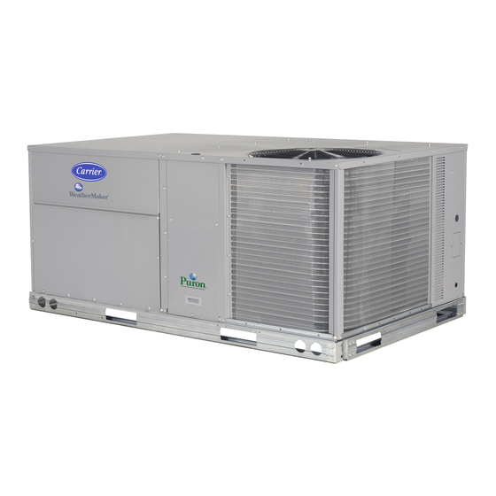
48TC**16
Single Package Rooftop
Gas Heating/Electric Cooling Unit
with Puronr (R --- 410A) Refrigerant
Size 16
NOTE: Read the entire instruction manual before starting
the installation
TABLE OF CONTENTS
. . . . . . . . . . . . . . . . . . . . . . . . . . . . . . .
. . . . . . . . . . . . . . . . . . . . . . . . . . . . . . . .
. . . . . . . . . . . . . . . . . . . . . . . . . . . . . . .
. . . . . . . . . . . . . . . . . . . . . . . . . . .
. . . . . . . . . . . . . . . . . . . . . . . . . .
. . . . . . . . . . . . . . . . . . . . . . . . . . . .
. . . . . . . . . . . . . . . . . . . . . . . . . . . .
. . . . . . . . . . . . . . . . . . . . . . . . .
. . . . . . . . . . . . . . . . . . . . . . . .
. . . . . . . . . . . . . . . . . . . . . . . . . . . . . . . .
Installation Instructions
. . . . . . . . . . . . . . . . . . . .
. . . . . . . . . . . . . . . . . .
. . . . . .
. . . . . . . . . . . . . . . . . . . . .
. . . . . . . . . . . . . . . . . . . . . .
. . . . . . . . . . . . . . . . . . . .
. . . . . . . . . . . . . . . . . . .
. . . . . . . . . . .
. . . . . . . . . . . . . .
. . . . . . . . . . . . . . . .
. . . . . . . . . . . . . . . . . . . . .
. . . . . . . . . . . . . . . . . . . . . . . .
. . .
. . . . . . . . . . . . . . . .
. . . . .
. . . . . . . . . . . . . . . . . . . . .
. . . . . . . . . . . . . . . . . . . .
. .
. . . . . . . . . . .
. . . .
2
4
4
. . . . . . . . . . . . . . . . . . . . . . . . . . . . . . .
4
5
5
5
5
5
5
5
5
5
5
7
7
8
8
9
9
9
10
10
11
11
13
14
14
15
15
. . . . . . . . . . . . . . . . . . . . . . .
. . . . . . . . . . . . . . . . . . . .
. . . . . . . . .
. . . . . . . . . . . . . . . . . . . . . . .
. . . . . . . . . . . . . . . . . . .
. . . . . . . . . .
. . . . . . . . . . . . . . . . .
. . . . . . . . .
. . . . . . . . . . . . . . . . . . . . . . . . . . . . .
. . . . . . . . . . . . . . . . . . . . . . . . . .
. . . . . . . . . . . . . . . . . . . . . . . . . . . .
. . . . . . . . . . . . . . . . . . . . . . .
. . . . . . . . . . . . . . . . . . . . . . . .
. . . . . . . . . . . . .
2
. . . . . . . . . . . . . . . . .
. . . . . . . . . . . . . . . . . . . .
. . . . . . . . .
. . . . . . . . . . . . . . . . . . . . . . . .
. . . . . . . . . . . . . . . . . . .
. . . . . . . . . . . . . . . . . . .
. . . . . . . . . . . . . . . . . . . . .
. . . . . . . . . . . . . . . . . .
. . . . . . . . . . . . . . . . . . . . .
. . . . . . . . .
. . . . . . . . . . . . . . . . . . . . . . . . . . . . .
. . . . . . . . . . . . . . . . . . . . . . . . . .
. . . . . . . . . . . .
. . . . . . . . . . . . .
2
. . . . . . .
15
16
18
18
18
18
. . . . . . .
19
19
20
. . . . . . . .
20
21
25
. . . . . . .
25
25
25
27
27
. . . . . .
27
28
28
28
29
30
30
30
30
30
31
32
35
. . . . . . .
35
35
35
36
36
Advertisement
Table of Contents

Related Manuals for Carrier 48TC**16


Summary of Contents for Carrier 48TC**16
-
Page 1: Table Of Contents
48TC**16 Single Package Rooftop Gas Heating/Electric Cooling Unit with Puronr (R --- 410A) Refrigerant Size 16 Installation Instructions NOTE: Read the entire instruction manual before starting the installation TABLE OF CONTENTS SAFETY CONSIDERATIONS .... -
Page 2: Safety Considerations
Outdoor Air Quality Sensor ....Space Relative Humidity Senor or Humidistat Smoke Detector/Fire Shutdown (FSD) Connecting Discrete Inputs ....Communication Wiring - - Protocols General . - Page 3 Vertical Connections / Economizer Horizontal Connections / Economizer C10864A Fig. 1 - - Unit Dimensional Drawing – 16 Size Unit...
-
Page 4: Installation
Fig. 1 - - Unit Dimensional Drawing – 16 Size Unit (cont.) INSTALLATION Jobsite Survey Complete the following checks before installation. 1. Consult local building codes and the NEC (National Electrical Code) ANSI/NFPA 70 for special installa- tion requirements. 2. Determine unit location (from project plans) or select unit location. -
Page 5: Roof Mount
Roof Mount — Check building codes weight requirements. Unit operating weight is shown in Table 1. Table 1 – Operating Weights 48TC**16 COMPONENT UNITS LB (KG) Base Unit 1380 (627) Economizer Vertical Horizontal Humidi--- MiZer System Powered Outlet Curb 14--- in/356 mm 24--- in/610 mm Step 2 —... - Page 6 C10772 Fig. 3 - - Roof Curb Details...
-
Page 7: Step 5 - Field Fabricate Ductwork
“C” “A” SEE DETAIL “A” MAX WEIGHT UNIT 48TC**16 2130 NOTES: 1. SPREADER BARS REQUIRED — Top damage will occur if spreader bars are not used. 2. Dimensions in ( ) are in millimeters. 3. Hook rigging shackles through holes in base rail, as shown in detail “A.” Holes in base rails are centered around the unit center of gravity. -
Page 8: Positioning On Curb
Positioning on Curb — For full perimeter curbs CRRFCURB074A00 and 075A00, the clearance between the roof curb and the front and rear base rails should be in (6.4 mm). The clearance between the curb and the end base rails should be retrofit applications with curbs CRRFCURB003A01 and 4A01, the unit should be position as shown in Fig. -
Page 9: Step 8 - Install Outside Air Hood
Step 8 — Install Outside Air Hood Economizer Hood Removal and Setup - - Factory Option — 1. The hood is shipped in knock- - down form and located in the return air compartment. It is attached to the economizer using two plastic tie- - wraps. 2. -
Page 10: Economizer Hood And Two- - Position Hood
Economizer Hood and Two- - Position Hood — NOTE: If the power exhaust accessory is to be installed on the unit, the hood shipped with the unit will not be used and must be discarded. Save the aluminum filter for use in the power exhaust hood assembly. -
Page 11: Step 10 - Install Gas Piping
Step 10 — Install Gas Piping Installation of the gas piping must be accordance with local building codes and with applicable national codes. In U.S.A., refer to NFPA 54/ANSI Z223.1 National Fuel Gas Code (NFGC). In Canada, installation must be accordance with the CAN/CSA B149.1 and CAN/CSA B149.2 installation codes for gas burning appliances. - Page 12 NOTE: If gas and/or electrical connections are not going to occur at this time, tape or otherwise cover the fittings so that moisture does not get into the building or conduit in the interim. CONNECTOR PLATE ASSEMBLY GASKET Fig. 18 - - Completing Installation of Thru- - the- - Base Option The thru- - base gas connector has male and female threads.
-
Page 13: Fire Or Explosion Hazard
When installing the gas supply line, observe local codes pertaining to gas pipe installations. Refer to the NFPA 54/ANSI Z223.1 NFGC latest edition (in Canada, CAN/CSA B149.1). In the absence of local building codes, adhere to the following pertinent recommendations: 1. -
Page 14: Step 12 - Make Electrical Connections
The piping for the condensate drain and external trap can be completed after the unit is in place. See Fig. 25. MINIMUM PITCH 1” (25mm) PER BASE RAIL 10’ (3m) OF LINE 2˝ (51) MIN OPEN VENT TO ROOF DRAIN DRAIN PLUG NOTE: Trap should be deep enough to offset maximum unit static difference. -
Page 15: Fire Hazard
Operation on improper line voltage or excessive phase imbalance constitutes abuse and may cause damage to electrical components. Such operation would invalidate any applicable Carrier warranty. NOTE: Check all factory and field electrical connections for tightness. Units Without Factory- - Installed Disconnect —... -
Page 16: Convenience Outlets
Lock- - out and tag- - out this switch, if necessary. Two types of convenience outlets are offered on the 48TC**16 : non- - powered and unit- - powered. Both types provide a 125- - volt GFCI (ground- - fault circuit- - interrupter) duplex receptacle rated at 15- - A behind a hinged waterproof access cover, located on the panel beneath the control box. - Page 17 Test the GFCI receptacle by pressing the TEST button on the face of the receptacle to trip and open the receptacle. Check for proper grounding wires and power line phasing if the GFCI receptacle does not trip as required. Press the RESET button to clear the tripped condition.
-
Page 18: Factory- - Option Thru- - Base Connections (Electrical Connections)
This device can be a thermostat (field- - supplied) or a PremierLink controller (available as factory- - installed option or as field- - installed accessory, for use on a Carrier Comfort Network or as a stand alone control) or the RTU... -
Page 19: Unit Without Thru- - Base Connection Kit
Typical Thermostat Terminal Connections O/B/Y2 (see Note) Note: Typical multi-function marking. Follow manufacturer’s configuration instructions to select Y2. Do not configure for O output. Field Wiring Fig. 38 - - Typical Low- - Voltage Control Connections Unit without Thru- - Base Connection Kit — Central Pass the thermostat control wires through the bushing on the Board... -
Page 20: Humidi- - Mizer R Control Connections
(units with PremierLinkt control). To connect the Carrier humidistat (HL38MG029): 1. Route the humidistat 2- - conductor cable (field- - supplied) through the bushing the unit’s louvered end panel (see Fig. - Page 21 HUMIDISTAT Fig. 42 - - Typical Humidi- - MiZer Adaptive Dehumidification System Humidistat Wiring EDGE Pro THERMIDISTAT O/W2/B SRTN Fig. 43 - - Typical Rooftop Unit with Humidi- - MiZer Adaptive Dehumidification System with EDGE Pro Thermidistat Device Unit CTB THERMOSTAT Humidi-MiZer™...
-
Page 22: Premierlinkt (Factory Option)
Scrolling Marquee are not suitable for use with latest PremierLink controller (Version 2.x).) The PremierLink control is factory- - mounted in the 48TC**16 unit’s main control box to the left of the Central Terminal Board (CTB) (see Fig. 45). Factory wiring is completed through harnesses connected to the Fig. - Page 23 C11202 Fig. 46 - - PremierLink Wiring Schematic...
- Page 24 C11203 Fig. 47 - - PremierLink Wiring Schematic with Humidi- - MiZer...
-
Page 25: Supply Air Temperature (Sat) Sensor
Supply Air Temperature (SAT) Sensor — On FIOP- - equipped 48TC**16 units, the unit is supplied with a supply- - air temperature (SAT) sensor (33ZCSENSAT). This sensor is a tubular probe type, approx 6- - inches (12.7 mm) in length. It is a nominal 10- - k ohm thermistor. -
Page 26: Field Connection
IAQ ---COM/OAQ ---COM/RH ---COM OAQ ---SEN/RH ---SEN CCN Gnd (WHT) AUX OUT(Power Exhaust) LEGEND: --- Space Temperature Sensor --- Space Temperature Sensor --- Carrier Comfort Network (communication bus) CMPSAFE --- Compressor Safety FILTER --- Dirty Filter Switch TB3 TERMINAL IAQ ---COM/OAQ ---COM/RH ---COM... -
Page 27: Space Sensors
Space Sensors — The PremierLink controller is factory- - shipped configured for Space Sensor Mode. A Carrier T- - 55 or T- - 56 space sensor must be used. T- - 55 space temperature sensor provides a signal of space temperature to the PremierLink control. -
Page 28: Economizer Controls
(4 to 20 mA) and ground (SIG COM) terminals on the OAQ sensor. See Fig. 54. Connect the 4 to 20 mA terminal to the TB3- - 13 terminal of the 48TC**16. Connect the SIG COM terminal to the TB3- - 11 terminal of the 48TC**16. -
Page 29: Space Relative Humidity Sensor Or Humidistat Connections
(field supplied). Do not over tighten screws. See Fig. 58. The sensor must be mounted vertically on the wall. The Carrier logo should be orientated correctly when the sensor is properly mounted. Avoid corner locations. Allow at least 4 ft between the sensor and any corner. -
Page 30: Smoke Detector/Fire Shutdown (Fsd)
(Space) Sensor Mode. The unit is factory- - wired for PremierLink FSD operation when PremierLink is factory- - installed. On 48TC**16 units equipped with factory- - installed Smoke Detector(s), the smoke implements the unit shutdown through its NC contact set connected to the unit’s CTB input. -
Page 31: Ccn Communication Bus
4000 ft, with no more than 60 total devices on any 1000- - ft section. Optically isolated RS- - 485 repeaters are required every 1000 ft. NOTE: Carrier device default is 9600 band. Communications Bus Wire Specifications: The CCN Communication Bus wiring is field- - supplied and field- - installed. -
Page 32: Rtu Open Control System
RTU Open Control System The RTU Open control is factory- - mounted in the 48TC**16 unit’s main control box, to the left of the CTB. See Fig. 66. Factory wiring is completed through harnesses connected to the CTB. Field connections for RTU Open sensors will be made at the Phoenix connectors on the RTU Open board. - Page 33 C11204 Fig. 67 - - RTU Open System Control Wiring Diagram...
- Page 34 C11205 Fig. 68 - - RTU Open System Control Wiring Diagram with Humidi- - MiZer...
-
Page 35: Supply Air Temperature (Sat) Sensor
RTU Open system. Supply Air Temperature (SAT) Sensor — On FIOP- - equipped 48TC**16 unit, the unit is supplied with a supply- - air temperature (SAT) sensor (33ZCSENSAT). This sensor is a tubular probe type, approx 6- - inches (12.7 mm) in length. -
Page 36: Space Temperature (Spt) Sensors
Space Temperature (SPT) Sensors — There are two types of SPT sensors available from Carrier, resistive input non-communicating (T55, T56, and T59) and Rnet communicating (SPS, SPPL, SPP, and SPPF) sensors. Each type has a variety of options consisting of: timed override button, set point adjustment, a LCD screen, and communication tie in. -
Page 37: Outdoor Air Quality Sensor
Wiring the Indoor Air Quality Sensor: For each sensor, use two 2- - conductor 18 AWG (American Wire Gage) twisted- - pair cables (unshielded) to connect the separate isolated 24 vac power source to the sensor and to connect the sensor to the control board terminals. To connect the sensor to the control, identify the positive (4 to 20 mA) and ground (SIG COM) terminals on the sensor. -
Page 38: Smoke Detector/Fire Shutdown (Fsd)
S J5- - 8 = 24 VAC source for dry contact S J5- - 7 = Signal input Smoke Detector/Fire Shutdown (FSD) — On 48TC**16 units equipped with factory- - installed Smoke Detector(s), the smoke implements the unit shutdown through its NC contact set connected to the unit’s CTB input. -
Page 39: Communication Wiring - - Protocols
Communication Wiring - - Protocols General — Protocols are the communication languages spoken by control devices. The main purpose of a protocol is to communicate information in the most efficient method possible. Different protocols exist to provide different kinds of information for different applications. In the BAS application, many different protocols are used, depending on manufacturer. -
Page 40: Local Access
Local Access — The BACview BACview Handheld: interface used to connect to the RTU Open to access the control information, read sensor values, and test the RTU, see Fig. 79. This is an accessory interface that does not come with the RTU Open controller and can only be used at the unit. -
Page 41: Outdoor Air Enthalpy Control
The LEDs on the RTU Open Control Board (see Fig. 65) show the status of certain functions: If this LED is on... Status is... Power RTU Open has power RTU Open is receiving data from the network segment RTU Open is transmitting data over the network segment The digital output is active The Run and Error LEDs indicate control module and network status If Run LED shows... -
Page 42: Smoke Detectors
Smoke Detectors Smoke detectors are available as factory- - installed options on 48TC**16 units. Smoke detectors may be specified for Supply Air only or for Return Air without or with economizer or in combination of Supply Air and Return Air. -
Page 43: Smoke Detector Locations
Air is introduced to the duct smoke detector sensor’s sensing chamber through a sampling tube that extends into the HVAC duct and is directed back into the ventilation system through a (shorter) exhaust tube. The difference in air pressure between the two tubes pulls the sampled air through the sensing chamber. - Page 44 Completing Installation of Return Air Smoke Sensor: 1. Unscrew the two screws holding the Return Air Sensor detector plate. See Fig. 85. Save the screws. 2. Remove the Return Air Sensor and its detector plate. 3. Rotate the detector plate so the sensor is facing out- wards and the sampling tube connection is on the bot- tom.
- Page 45 Table 10 – Unit Wire/Fuse or HACR Breaker Sizing Data COMBUSTION FAN MOTOR NOM. V ---Ph---Hz TYPE 208/230---3---60 0.48 HIGH 460--- 3--- 60 0.25 HIGH 575--- 3--- 60 0.24 HIGH Table 10 — Unit Wire/Fuse or HACR Breaker Sizing Data (cont) COMBUSTION FAN MOTOR NOM.
-
Page 46: Step 13 - Adjust Factory- -Installed Options
Economizer Step 13 — Adjust Factory- -Installed Options Smoke Detectors — Smoke detector(s) will be connected at the Central Terminal Board (CTB), at terminals marked “Smoke Shutdown”. Remove jumper JMP 3 when ready to energize unit. EconoMi$er IV Occupancy Switch — Refer to Fig. - Page 48 Catalog No: 48TC ---14SI Copyright 2011 Carrier Corp. D 7310 W. Morris St. D Indianapolis, IN 46231 Printed in U.S.A. Edition Date: 05/11 Manufacturer reserves the right to change, at any time, specifications and designs without notice and without obligations.
Need help?
Do you have a question about the 48TC**16 and is the answer not in the manual?
Questions and answers