Table of Contents
Advertisement
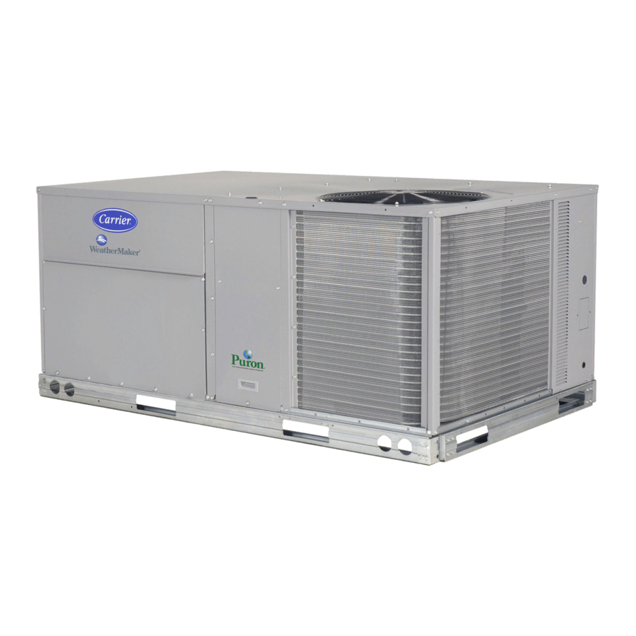
48TC*D08---D14
Nominal 7.5 to 12.5 Tons
With Puron® (R---410A) Refrigerant
Service and Maintenance Instructions
TABLE OF CONTENTS
. . . . . . . . . . . . . . . . . . . . . . . . . . . . . . . . . . . .
. . . . . . . . . . . . . . . . . . . . . . . . .
. . . . . . . . . . . . . . . . . . . . . . . . .
. . . . . . . . . . . . . . . . . . . . . . . . . . . . . .
. . . . . . . . . . . . . . . . . . . . . . . .
. . . . . . . . . . . . . . . . . . . . . . . . . . . . . . . . .
. . . . . . . . . . . . . . . . . . . .
. . . . . . . . . . .
. . . . . . . . . . . . . .
. . . . . . . . . . . . . .
. . . . . . . . . . . . . . . .
. . . . . . . . . . . . . . . . . . . .
. . . . . . . . . . . . . . . . . . . . . . .
. . . . . . . . . . . . . . . . . . . . . .
. . . . . . . . . . . . . . . . . .
. . . . . . . . . . . . . . . . . . .
. . . . . . . . . . . . . . . . . .
. . . . . . . . . . . . . . . . . . . . . .
. . . . . . . . . .
. . . . . . . . . . . . . . . .
. . . . . . . . . . . . . . . . . . . . .
. . . . . . . . . . . . . . . . .
. . . . . . . . . . . . . . . .
. . . . . . . . . . .
. . . . . . . .
. . . . . . . . . . . . . . . . . .
SAFETY CONSIDERATIONS
1
Installation and servicing of air-conditioning equipment
can be hazardous due to system pressure and electrical
2
components. Only trained and qualified service personnel
4
should
install,
6
equipment. Untrained personnel can perform the basic
maintenance functions of replacing filters. Trained service
8
personnel should perform all other operations.
10
When working on air-conditioning equipment, observe
16
precautions in the literature, tags and labels attached to
17
the unit, and other safety precautions that may apply.
24
Follow all safety codes. Wear safety glasses and work
gloves. Use quenching cloth for unbrazing operations.
25
Have fire extinguishers available for all brazing
35
operations.
36
Follow all safety codes. Wear safety glasses and work
44
gloves. Use quenching cloth for brazing operations. Have
57
fire extinguisher available. Read these instructions
thoroughly and follow all warnings or cautions attached to
66
the unit. Consult local building codes and National
69
Electrical Code (NEC) for special requirements.
69
Recognize safety information. This is the safety- - alert
71
symbol
. When you see this symbol on the unit and in
71
instructions or manuals, be alert to the potential for
personal injury.
75
85
Understand the signal words DANGER, WARNING, and
CAUTION. These words are used with the safety- - alert
.
87
symbol. DANGER identifies the most serious hazards
88
which will result in severe personal injury or death.
90
WARNING signifies a hazard which could result in
personal injury or death. CAUTION is used to identify
96
unsafe practices which may result in minor personal
injury or product and property damage. NOTE is used to
97
highlight suggestions which will result in enhanced
98
installation, reliability, or operation.
repair,
or
service
air-conditioning
Advertisement
Table of Contents


Need help?
Do you have a question about the 48TC*D08 and is the answer not in the manual?
Questions and answers