Table of Contents
Advertisement
Quick Links
Installation and operating instructions
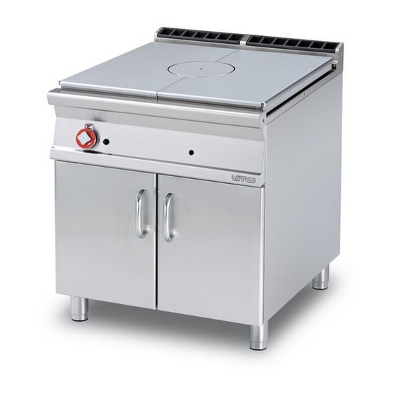
PROFESSIONAL GAS FULL-PLATE
COOKER
TP-98G TPF-98G TPF-98GE TP2-912G TPF2-912G V TPF2-912G
TPF2-912GEV TPF2-912GE TPT-98G TP2T-912G TPFV-98GE
TPFV2-912GEV
Model LIBR.ISTR.TP90G
Code 563009202
Review 1
Edition date 23/11/2018
Language English
LOTUS S.p.A.
Via Calmaor, 46
31020 San Vendemiano
+39 0438 778020
+39 0438 778277
Translation of the original instructions
Advertisement
Table of Contents

Related Manuals for Lotus TP-98G


Summary of Contents for Lotus TP-98G
- Page 1 Installation and operating instructions PROFESSIONAL GAS FULL-PLATE COOKER TP-98G TPF-98G TPF-98GE TP2-912G TPF2-912G V TPF2-912G TPF2-912GEV TPF2-912GE TPT-98G TP2T-912G TPFV-98GE TPFV2-912GEV Model LIBR.ISTR.TP90G Code 563009202 Review 1 Edition date 23/11/2018 Language English LOTUS S.p.A. Via Calmaor, 46 31020 San Vendemiano...
-
Page 2: Table Of Contents
Contents Contents INTRODUCTION ......................... Installation drawing ........................Components..........................Example installation of the appliance................... GENERAL INFORMATION......................Declaration of compliance......................User information, RAEE Directive on waste electrical and electronic equipment ......Technical data table ........................INSTALLATION........................... Delivery checks ..........................Removing the packaging ......................Mechanical installation ......................... -
Page 3: Introduction
INTRODUCTION 1 INTRODUCTION Installation drawing FIG. 1 TP…-9G.. A Data Plate B Electrical connection C Gas connection FIG. 2 TP...T A Data Plate C Gas connection Translation of the original instructions... -
Page 4: Components
INTRODUCTION Components FIG. H Translation of the original instructions... - Page 5 INTRODUCTION FIG. B 1 Flame open by-pass 2 Oven by-pass FIG.C (FLAMES) 1 Flame injector 2 Air adjustment 3 Pilot Translation of the original instructions...
- Page 6 INTRODUCTION FIG. D (Fire pilot) 1 Pilot bracket screw 2 Pilot bracket 3 Pilot air bushing 4 Pilot injector 5 Injector screw 6 Spring 7 Extends drainage Translation of the original instructions...
- Page 7 INTRODUCTION FIG. F (Oven pilot) 1 Pilot light nozzle 2 Ignition spark plug 3 Extends drainage 4 Pilot bracket FIG. E 1 Oven injector 2 Oven air regulation Translation of the original instructions...
- Page 8 INTRODUCTION FIG. G Burner air adjustment FIG. I 1 Injector 2 Pilot Translation of the original instructions...
- Page 9 INTRODUCTION WIRING DIAGRAM OVEN GN 2/1 (H) 1 Switch 2 Power supply terminal board 3 Heating element 4 White indicator light 5 Green indicator light 6 Thermostat 7 Safety thermostat Translation of the original instructions...
- Page 10 INTRODUCTION WIRING DIAGRAM OVEN GN 3/1 (I) 1 Switch 2 Power supply terminal board 3 Heating element 4 White indicator light 5 Green indicator light 6 Thermostat 7 Safety thermostat Translation of the original instructions...
- Page 11 INTRODUCTION VENTILATED ELECTRICAL OVEN 1 Switch 2 Condenser 3 Power supply terminal board 4 Switching terminal board 5 Motor 6 Heating element 7 White indicator light 8 Green indicator light 9 Safety thermostat 10 Thermostat Translation of the original instructions...
-
Page 12: Example Installation Of The Appliance
INTRODUCTION Example installation of the appliance Translation of the original instructions... -
Page 13: General Information
GENERAL INFORMATION 2 GENERAL INFORMATION Declaration of compliance The manufacturer declares that the appliances comply with the requirements of the regulation GAR 2016/426 for the gas part and directive 2014/30/EU,2014/35/EU for the electrical part. Installation must be performed in compliance with current regulations, especially with regard to ventilation of the premises and the exhaust gas evacuation system. -
Page 14: User Information, Raee Directive On Waste Electrical And Electronic Equipment
FITTING MODEL DIMENSIONS FLAME FLAME OVEN OVEN ISO 7-1 TYPE 12 kW 8.5 kW 13 kW (kW) 10 kW 7 kW TP-98G 80x90x90h R 3/4GM TPF-98G 80x90x90h 20,5 R 3/4GM TPF-98GE 80x90x90h R 3/4GM TP2-912G 120x90x90h R 3/4GM TPF2-912GV 120x90x90h... - Page 15 GENERAL INFORMATION Electrical technical data table TP S90G MAXIMUM MAXIMUM ELECTRIC POWER SUPPLY DIMENSION Emissivity MODEL POWER SUPPLY ABSORPTION CABLE dB (A) POWER silicon type (kW) TPF-98GE 80x90x90h 400V~3N 50/60Hz 10,9 5 x 1,5 mm² TPF2-912GEV 120x90x90h 400V~3N 50/60Hz 10,9 5 x 1,5 mm²...
- Page 16 GENERAL INFORMATION DESIGN ASSEMBLY/TRANSFORMATION ELECTRICAL LINKING TERMINAL BLOCK PERNIONS (see technical data table) · POWER SUPPLY CONNECTION · HEATING ELEMENT CONNECTION Translation of the original instructions...
-
Page 17: Installation
INSTALLATION 3 INSTALLATION Delivery checks On delivery, it is important to check the following: · External conditions of the packaging · The general status of the equipment · The conformity of the model with the information in the technical data plate and the instruction manual ·... - Page 18 INSTALLATION Warning Installation operations, any conversion to other types of gas and start-up must only be performed by qualified personnel, in accordance with current regulations. Gas systems, electrical connections and premises where the appliances are installed must comply with current regulations in the country of installation;...
- Page 19 INSTALLATION valve and fast-closing valve. Once installation is complete, make sure that there are no gas leaks from the fittings; to do this, do not use a naked flame but substances that do not cause corrosion, such as solutions of soapy water or leak detectors.
- Page 20 INSTALLATION - "A" type devices (see data plate) "A" type appliances must discharge combustion products into appropriate hoods, or similar devices, connected to an efficient fume stack or directly to the outside. (Natural evacuation) Fig. 1 If this is not possible, using an air suction device connected directly to the outside is permitted (Forced Evacuation) Fig.2, having a flow capacity not lower than the value defined in point 4.3 of the UNI-CIG 8723 standard.
- Page 21 INSTALLATION 1 Windproof fume stack (fig.3) - Extractor hood (fig.4) 2 Servo system "B11" type appliances are supplied on request with a hood or a hood and windproof fume stack to be assembled and delivered separately. Translation of the original instructions...
-
Page 22: Burners Technical Data Table (Itgb)
BURNERS TECHNICAL DATA TABLE (ITGB) 4 BURNERS TECHNICAL DATA TABLE (ITGB) Burners technical data table Technical data table - Burners TP S90G 12.68 kWh/KG 12.87 kWh/KG 9.45 kWh/m3st. BUTANE PROPANE METHANE H 30 mbar 37 mbar 20 mbar Burner max 7 kW - min 1.8 kW ... -
Page 23: Instructions For Use
INSTRUCTIONS FOR USE 5 INSTRUCTIONS FOR USE General information This appliance must only be used for its expressly intended purpose for cooking or heating food. Any other use is considered improper. The appliance is also intended for industrial use and must only be used by personnel trained for use and aware of the risks that the hot element entails. -
Page 24: Switching The Main Burner Off
INSTRUCTIONS FOR USE Switching the main burner off · Turn the knob into position . The burner turns OFF and only the pilot flame remains ON Turning the appliance off · Press and turn the gas cock knob to position "0". This control blocks the gas supply to both the main burner and the pilot burner ... -
Page 25: Turning On And Adjusting The Fan Oven
INSTRUCTIONS FOR USE · Also turn the knob of the selector, setting one of the three positions Top + bottom heating element Bottom heating element Top heating element Turning on and adjusting the fan oven The hot air put in circulation by the fan is distributed in the entire oven chamber, ensuring even cooking. The uniform heating of the chamber makes it possible to cook different foods at the same time on different levels. -
Page 26: Cooking Table For The Fan Oven
INSTRUCTIONS FOR USE Cooking table for the fan oven Ventilated electrical oven cooking table Guide no. Temperature Min. cooking Type of food from the Quantity Kg °C time bottom Sweets With a beaten dough, in a mould With a beaten dough, without a mould 1-3-4 Shortcrust pastry, cake base 1-3-4... - Page 27 INSTRUCTIONS FOR USE Note · The indication of use of the levels shown in the table is recommended when cooking on multiple levels · The indicated times refer to cooking on only one level. Add 5-10’ when cooking on multiple levels ·...
-
Page 28: Maintenance
MAINTENANCE 6 MAINTENANCE Routine When using the appliance over time, it is essential to perform regular maintenance to ensure safe operation. We therefore recommend stipulating a service contract. Caution Maintenance must only be performed by specialist personnel in compliance with current ... -
Page 29: Substituting The Nozzle In The Oven Burner
MAINTENANCE After conversion to another type of gas, update the technical data plate to indicate the type of gas for which the appliance has been converted. Substituting the nozzle in the oven burner · Remove the base of the oven ·... -
Page 30: Cleaning
CLEANING 7 CLEANING Routine cleaning Caution The use of flammable fluids to clean the appliance is forbidden To ensure hygiene and the durability of the appliance, perform external cleaning on a regular basis, taking care not to damage the cables and the electrical connections. Before starting cleaning, disconnect the appliance from the power supply.
Need help?
Do you have a question about the TP-98G and is the answer not in the manual?
Questions and answers