U-Line H-3616 Quick Start Manual
Hide thumbs
Also See for H-3616:
- Assembly instructions manual (9 pages) ,
- Instruction manual (16 pages)
Advertisement
Quick Links
π
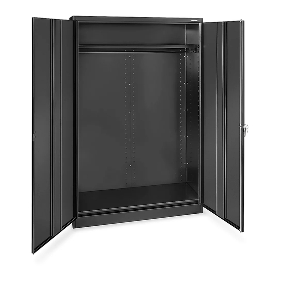
H-3616
WARDROBE
CABINET
PAGE 1 OF 5
1-800-295-5510
uline.com
TOOLS NEEDED
CAUTION! Some parts may have sharp
edges. Take care when handling various
pieces to avoid injury. For your safety, wear
work gloves when assembling.
11/32" Nut Driver
(included)
Flathead Screwdriver
Rubber Mallet
0315 IH-3616
Advertisement

Related Manuals for U-Line H-3616


Summary of Contents for U-Line H-3616
- Page 1 π H-3616 1-800-295-5510 uline.com WARDROBE CABINET TOOLS NEEDED 11/32” Nut Driver (included) Flathead Screwdriver Rubber Mallet CAUTION! Some parts may have sharp edges. Take care when handling various pieces to avoid injury. For your safety, wear work gloves when assembling.
-
Page 2: Handle Assembly
PARTS PRIMARY ASSEMBLY HANDLE ASSEMBLY DESCRIPTION QTY. DESCRIPTION QTY. Back Panel Locking Handle with Keys and Dummy Handle (Set) Right Side Panel Cotter Pin Left Side Panel Lock Bar Guide Lock Bar (Set) Shelf Locking Cam Left Door Right Door Sill Bolts (#8-32 x 3/8") Nuts (#8-32) - Page 3 ASSEMBLY INSTRUCTIONS ASSEMBLING CABINET 3. Attach the top (4) to the unit by sliding the outer flange over the back of the unit and the side flange Place the back (1) on a protected surface. The on the top over the side panel. The threaded studs bottom flange should be facing upward.
- Page 4 ASSEMBLY CONTINUED 5. Attach the sill (8) to the sides. Place nuts loosely on Attach the right bracket in the same way. Slide the each of the studs and slide the ends of the sill into coat rod (12) through the holes in the brackets. the slots on both sides of the unit.
-
Page 5: Attaching Handle
ASSEMBLY CONTINUED Figure 8 Figure 10 ATTACHING HANDLE Figure 11 Figure 12 1. Place the locking handle (14) on the right hand door and fasten with two slotted bolts and lock washers. (See Figure 8) 2. Turn the handle to the open position (See Figure 9) and place the locking cam (19) over the square shank of the door handle.
Need help?
Do you have a question about the H-3616 and is the answer not in the manual?
Questions and answers