
Related Manuals for Riello PRESS 450 T/N


Summary of Contents for Riello PRESS 450 T/N
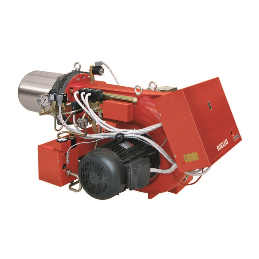
- Page 1 Installation, use and maintenance instructions Heavy oil burner Three stage operation CODE MODEL TYPE 3439347 PRESS 450 T/N 469 M1 20184179 (2) - 01/2021...
- Page 2 Translation of the original instructions...
-
Page 3: Table Of Contents
Contents Declarations....................................3 Information and general warnings............................4 Information about the instruction manual ........................4 Guarantee and responsibility............................5 Safety and prevention................................6 Introduction.................................. 6 Personnel training ............................... 6 Technical description of the burner ............................7 Burner designation ..............................7 Models available................................ - Page 4 Contents Maintenance ....................................27 Notes on safety for the maintenance .........................27 Maintenance programme ............................27 Opening and closing the burner ..........................28 Faults - Possible causes - Solutions............................29 Appendix - Accessories ................................31 Appendix - Electrical panel layout............................32 20184179...
-
Page 5: Declarations
Declarations Declarations Declaration of Conformity in accordance with ISO / IEC 17050-1 These products are in compliance with the following Technical Standards: • EN 12100 • EN 267 According to the European Directives: 2006/42/CE Machine Directive 2014/35/UE Low Voltage Directive EMC 2014/30/UE Electromagnetic Compatibility The quality is guaranteed by a quality and management system certified in accordance with ISO 9001:2015. -
Page 6: Information And General Warnings
Information and general warnings Information and general warnings Information about the instruction manual 2.1.1 Introduction WARNING: MOVING PARTS The instruction manual supplied with the burner: This symbol indicates that you must keep limbs is an integral and essential part of the product and must not away from moving mechanical parts;... -
Page 7: Guarantee And Responsibility
Information and general warnings 2.1.4 Delivery of the system and the instruction The system supplier must carefully inform the user about: – the use of the system; manual – any further tests that may be required before activating the When the system is delivered, it is important that: system;... -
Page 8: Safety And Prevention
Safety and prevention Safety and prevention Introduction The burners have been designed and built in compliance with the type and pressure of the fuel, the voltage and frequency of the current regulations and directives, applying the known technical electrical power supply, the minimum and maximum deliveries for safety rules and envisaging all the potential danger situations. -
Page 9: Technical Description Of The Burner
3N / 400V / 50Hz 3/230/50 3 / 230V / 50Hz Voltage of auxiliaries: 230/50/60 230V / 50-60Hz 110/50/60 110V / 50-60Hz PRESS 3N/400/50 230/50 BASIC DESIGNATION EXTENDED DESIGNATION Models available Designation Voltage Start-up Code PRESS 450 T/N 3N/400/50 Star/triangle 3439347 20184179... -
Page 10: Technical Description Of The Burner
Technical description of the burner Technical description of the burner Technical data MODEL PRESS 140 P/N Output 855 ÷ 5130 kW Delivery kg/h 75 ÷ 450 kg/h (see the following tables) Fuel Heavy oil - max viscosity at 50 °C 50 (7°E) up to 500 (65°E) with kit Operation •... -
Page 11: Operation And Efficiency Of The Burner
Technical description of the burner Operation and efficiency of the burner Thermal power - Output Minimum Maximum STAGE kg/h kg/h 1710 nozzle: ignition phase 1710 3420 nozzle: intermediate phase 2560 5130 nozzle: operation phase Thermal power - Output Minimum Maximum STAGE kg/h kg/h... -
Page 12: Overall Dimensions
T-T(1) U - U ( 1 ) 20186876 Fig. 1 T-T (1) U-U (1) PRESS 450 T/N 1090 435 - 565 1665 - 1820 Tab. D Standard equipment Flexible hoses ............. No. 2 Grommet ..............No. 7 Screws................. -
Page 13: Firing Rates
Technical description of the burner Firing rates During operation, burner output varies within a minimum and a The FIRING RATE was obtained with an ambient maximum limit. temperature of 20°C and a barometric pressure of 1000 mbar (approx. 100m above sea level), with MINIMUM OUTPUT: can drop down to: 75 kg the combustion head adjusted as shown on page ATTENTION... -
Page 14: Burner Description
Technical description of the burner Burner description D2802 Fig. 4 Suction line Return line Air shutter opening motor Pump pressure adjustment screw Manometer plug Vacuometer plug Low limit thermostat Electric board Cable clamps 10 Control box reset push-button and lock-out lamp 11 Adjustment thermostat 12 Regulating bush for combustion head 13 Wiring terminal board... -
Page 15: Control Box Rmo88
The control box RMO88... is a safety device! ATTENTION Avoid opening or modifying it, or forcing its opera- tion. Riello S.p.A. cannot assume any responsibil- ity for damage resulting from unauthorised interventions! All interventions (assembly and installation operations, assistance, etc.) must be carried out by qualified personnel. -
Page 16: Installation
Installation Installation Notes on safety for the installation After carefully cleaning all around the area where the burner is to The installation of the burner must be carried out be installed, and arranging for the environment to be illuminated by qualified personnel, as indicated in this manual correctly, proceed with the installation operations. -
Page 17: Operating Position
The position of the threaded holes can be marked using the thermal insulation screen supplied with the burner. For the combustion head protrusion follow the indications provided by the boiler manufacturer. MODEL Ø PRESS 450 T/N M 20 Tab. E 20188668 Fig. 8 Blast tube length... -
Page 18: Securing The Burner To The Boiler
Installation Securing the burner to the boiler Provide an adequate lifting system. Be careful as some drops of fuel may leak out D2590 during this phase. To separate the burner from the cast iron blast tube, proceed as follows: remove the cover 1)(Fig. 10), the split pin and pin 2), the nuts 3) and the screws 4). -
Page 19: Nozzle Installation
267 standard. In order to guarantee that emissions do not vary, First of all state the maximum output required with all three recommended and/or alternative nozzles specified by Riello in nozzles in operation. the Instruction and warning booklet should be used. -
Page 20: Fuel Oil Supply
Installation 6.11 Fuel oil supply 6.11.1 Ring supply line Explosion danger due to fuel leaks in the For heavy oil with viscosity up to 50°E/50°C. presence of a flammable source. The oil could easily flow through the pipes if those are Precautions: avoid knocking, attrition, sparks and properly seized, protected and heated (by electricity, steam heat. -
Page 21: Pump Pressure
Installation 6.11.2 Gravity supply line L meters meters ø 1 ” ø 1 ” Make sure that the hoses to the pump supply and return line are installed correctly. CAUTION Install the hoses where they cannot be stepped on or come into contact with hot surfaces of the boiler. -
Page 22: Electrical Connections
Installation 6.13 Electrical connections Notes on safety for the electrical wiring The electrical wiring must be carried out with the electrical supply disconnected. Electrical wiring must be made in accordance with the regulations currently in force in the country of destination and by qualified personnel. -
Page 23: Start-Up, Calibration And Operation Of The Burner
Start-up, calibration and operation of the burner Start-up, calibration and operation of the burner Notes on safety for the first start-up The first start-up of the burner must be carried out Check the correct working of the adjustment, by qualified personnel, as indicated in this manual command and safety devices. -
Page 24: Air Shutters Adjustments
Start-up, calibration and operation of the burner Air shutters adjustments The adjustment of the air shutters shall be set each time, with ref- erence to the nozzles deliveries and the combustion chamber pressurization. Fig. 17 shows the positioning of the air shutters. Fig. -
Page 25: Atomising Temperature Setting
Start-up, calibration and operation of the burner Atomising temperature setting 7.5.1 Thermostat for adjustment - maximum value - D2811 minimum value Electronic adjustment thermostat by means of information re- layed from a PT100 probe immersed in the oil in the delivery manifold, the thermostat adjusts spray temperature. -
Page 26: Operation Sequence Of The Burner
Start-up, calibration and operation of the burner Operation sequence of the burner 7.6.1 Burner start-up program Normal Lock-out due to no ignition Thermostat Motor Ignition transformer Pre-purge flame valve flame valve flame valve Lock-out lamp D2848 Fig. 23 ) Factory setting: 20 s. D3211 This time determines the heavy oil temperature at ignition. -
Page 27: Burners Start-Up Cycle Diagnostics
Burners start-up cycle diagnostics Burners start-up cycle diagnostics Burner start-up cycle diagnostics During start-up, indication is according to the colour code table 8.1.1 Resetting of control box and diagnostics use (Tab. J). The control box features a diagnostics function through which any causes of malfunctioning are easily identified (indicator: RED Sequences Colour code... -
Page 28: Final Checks (With Burner Operating)
Burners start-up cycle diagnostics Final checks (with burner operating) the burner should start and then go into lockout after about Block out the UV sensor and switch on the control 10 seconds from the opening of the 1st stage working devices: valve. -
Page 29: Maintenance
Maintenance Maintenance Notes on safety for the maintenance The periodic maintenance is essential for the good operation, Before carrying out any maintenance, cleaning or checking safety, yield and duration of the burner. operations: It allows you to reduce consumption and polluting emissions and to keep the product in a reliable state over time. -
Page 30: Opening And Closing The Burner
Maintenance 9.2.3 Safety components The safety components should be replaced at the end of their life cycle indicated in the following table. The specified life cycles do not refer to the warranty terms indicated in the delivery or payment conditions. Safety Life cycle component... -
Page 31: Faults - Possible Causes - Solutions
Faults - Possible causes - Solutions Faults - Possible causes - Solutions In the event the burner stops, in order to prevent In the event there are further lockouts or faults any damage to the installation, do not unblock the with the burner, the maintenance interventions burner more than twice in a row. - Page 32 Faults - Possible causes - Solutions 7 x blinks Flame loss Poorly adjusted head Adjust The ignition electrodes are Adjust them Fan air damper badly adjusted: Adjust 1st nozzle is too big (pulsa- Reduce the flow rate of the 1st nozzle 1st nozzle too small (flame Increase the flow rate of the 1st nozzle 1st nozzle is dirty or deformed...
-
Page 33: A Appendix - Accessories
Appendix - Accessories Appendix - Accessories Soundproofing box kit Burner Type dB(A) Code PRESS 450 T/N 3010376 Burner support kit Burner Code PRESS 450 T/N 3000731 Self-cleaning filter kit Burner Code Diameter 1” 1/2 (60° E at 50°C) 3010022 Thermostatic heater with LED... -
Page 34: Appendix - Electrical Panel Layout
Appendix - Electrical panel layout Appendix - Electrical panel layout Index of layouts Reference indication RMO 88 ... functional layout RMO 88 ... functional layout Functional layout Functional layout Electrical wiring that is the responsibility of the installer Reference indication / 1 . - Page 35 Appendix - Electrical panel layout 20170392...
- Page 36 Appendix - Electrical panel layout 20170392...
- Page 37 Appendix - Electrical panel layout 20170392...
- Page 38 Appendix - Electrical panel layout 20170392...
- Page 39 Appendix - Electrical panel layout 20170392...
- Page 40 Appendix - Electrical panel layout WIRING DIAGRAM KEY Electrical control box Suppressor Pre-heater contactor Three-phase fuses Pre-heater three-phase fuses Flame sensor Remote lockout signalling Motor lockout signalling Burner manual ON/OFF switch (optional) stage signalling stage signalling stage signalling Burner terminal board Fan motor Three-phase disconnecting switch Three-phase disconnecting switch...
- Page 44 RIELLO S.p.A. I-37045 Legnago (VR) Tel.: +39.0442.630111 http:// www.riello.it http:// www.riello.com Subject to modifications...
Need help?
Do you have a question about the PRESS 450 T/N and is the answer not in the manual?
Questions and answers