Table of Contents
Advertisement
Quick Links
Installation, use and maintenance instructions
Heavy oil burners
GB
Progressive two-stage or modulating operation
CODE
20169237
20169238
20169239
20169227
20169240
20169241
20169242
20169246
MODEL
PRESS 140 P/N
PRESS 140 P/N
PRESS 200 P/N
PRESS 200 P/N
PRESS 300 P/N
PRESS 300 P/N
PRESS 450 P/N
PRESS 450 P/N
TYPE
471 M1
471 M1
472 M1
472 M1
473 M1
473 M1
474 M1
474 M1
20170392 (2) - 12/2020
Advertisement
Table of Contents

Related Manuals for Riello PRESS 140 P/N


Summary of Contents for Riello PRESS 140 P/N
- Page 1 Installation, use and maintenance instructions Heavy oil burners Progressive two-stage or modulating operation CODE MODEL TYPE 20169237 PRESS 140 P/N 471 M1 20169238 PRESS 140 P/N 471 M1 20169239 PRESS 200 P/N 472 M1 20169227 PRESS 200 P/N 472 M1...
- Page 2 Translation of the original instructions...
-
Page 3: Table Of Contents
Contents Declarations....................................2 Information and general warnings............................3 Information about the instruction manual ..............................3 Guarantee and responsibility ..................................4 Safety and prevention................................5 Introduction ........................................5 Personnel training ......................................5 Technical description of the burner ............................6 Burner designation ......................................6 Models available ......................................6 Technical description of the burner ............................ -
Page 4: Declarations
The quality is guaranteed by a quality and management system certified in accordance with ISO 9001:2015. Legnago, 21.04.2018 General Manager Research and Development Director RIELLO S.p.A. - Burners Department RIELLO S.p.A. - Burners Department Eng. U. Ferretti Eng. F. Comencini... -
Page 5: Information And General Warnings
Information and general warnings Information and general warnings Information about the instruction manual 2.1.1 Introduction WARNING: MOVING PARTS The instruction manual supplied with the burner: This symbol indicates that you must keep limbs is an integral and essential part of the product and must not away from moving mechanical parts;... -
Page 6: Guarantee And Responsibility
Information and general warnings 2.1.4 Delivery of the system and the instruction The system supplier must carefully inform the user about: – the use of the system; manual – any further tests that may be required before activating the When the system is delivered, it is important that: system;... -
Page 7: Safety And Prevention
Safety and prevention Safety and prevention Introduction The burners have been designed and built in compliance with the type and pressure of the fuel, the voltage and frequency of the current regulations and directives, applying the known technical electrical power supply, the minimum and maximum deliveries for safety rules and envisaging all the potential danger situations. -
Page 8: Technical Description Of The Burner
230V / 50-60Hz 110/50/60 110V / 50-60Hz PRESS 3N/230-400/50 230/50 BASIC DESIGNATION EXTENDED DESIGNATION Models available Designation Voltage Start-up Code PRESS 140 P/N 3/230-400/50 Direct 20169237 PRESS 140 P/N 3/230-400/50 Direct 20169238 PRESS 200 P/N 3/230-400/50 Direct 20169239 PRESS 200 P/N... -
Page 9: Technical Description Of The Burner
Technical description of the burner Technical description of the burner Technical data MODEL PRESS 140 P/N PRESS 200 P/N PRESS 300 P/N PRESS 450 P/N Output 400-1600 570-2280 683-3420 1140-5130 Delivery kg/h 35-140 50-200 60-300 100-450 Fuel Heavy oil 50 (7°E) - max viscosity at 50 °C... -
Page 10: Electrical Data
Technical description of the burner Electrical data MODEL PRESS 140 P/N PRESS 200 P/N CODE 20169237 - 20169238 20169227 - 20169239 3N ~ 230-400 Electrical power supply Electrical motor 2900 2930 230/400 230/400 9.7-5.6 13.9-8 Heater Ignition transformer Primary: 2.3A - Secondary: 2x6 kV - 35 mA... -
Page 11: Overall Dimensions
S9889 F - F O - O Fig. 1 F - F O - O PRESS 140 P/N 323 - 433 1233 - 1343 PRESS 200 P/N 352 - 462 1262 - 1372 PRESS 300 P/N 1020... -
Page 12: Firing Rates
20°C and a barometric pressure of MINIMUM OUTPUT: can drop down to: 1000 mbar (approx. 100m above sea level), with PRESS 140 P/N 35 kg Maximum modulating ratio is 1 - 3 the combustion head adjusted as shown on page... -
Page 13: Test Boiler
Technical description of the burner Test boiler The burner/boiler combination does not pose any problems if the In Fig. 3 you can see the diameter and length of the test boiler is EC approved and its combustion chamber dimensions combustion chamber. are similar to those indicated in the diagram (Fig. -
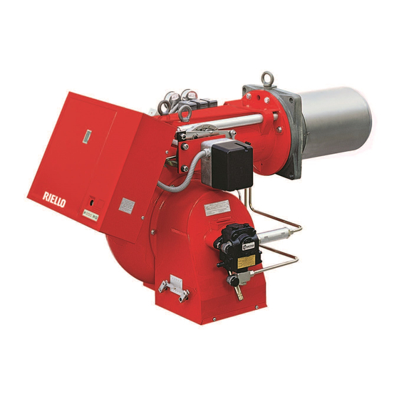
Page 14: Burner Description
Technical description of the burner Burner description 20172325 Fig. 4 Suction connection Pump pressure regulator Return connection Pressure gauge connection (PRESS 140 - G 1/8) Pressure gauge connection (PRESS 200-300-450 - G 1/4) Vacuometer connection (PRESS 140 - G 1/2) Vacuometer connection (PRESS 200-300-450 - G 1/4) Maximum temperature thermostat Minimum temperature thermostat... -
Page 15: Electrical Panel Description
Technical description of the burner Electrical panel description 20172327 Fig. 5 Fan motor thermal relay and contactor (for direct starter version only) Ignition transformer Filter to protect against radio disturbance Servomotor connector Pre-heater contactor Terminal board for electric connection Relay Timed relay Relay 10 Electronic thermostat... -
Page 16: Control Box Rfgo-A23
Technical description of the burner Control box RFGO-A23 Important notes To avoid accidents, material or environmental damage, observe the following instructions! The control box is a safety device! Avoid opening ATTENTION or modifying it, or forcing its operation. The Manufacturer cannot assume any responsibility for damage resulting from unauthorised work! ... -
Page 17: 5.10 Servomotor Sqm40
Technical description of the burner 5.10 Servomotor SQM40 ... Important notes To avoid accidents, material or environmental damage, observe the following instructions! Avoid opening, modifying forcing ATTENTION servomotor. All interventions (assembly and installation operations, assistance, etc.) must be carried out by qualified personnel. ... -
Page 18: Installation
Installation Installation Notes on safety for the installation After carefully cleaning all around the area where the burner is to The installation of the burner must be carried out be installed, and arranging for the environment to be illuminated by qualified personnel, as indicated in this manual correctly, proceed with the installation operations. -
Page 19: Operating Position
MODEL PRESS 140 P/N TC PRESS 200 P/N TC PRESS 300 P/N TC PRESS 450 P/N TC... -
Page 20: Securing The Burner To The Boiler
Installation Securing the burner to the boiler Provide an adequate lifting system. Be careful as some drops of fuel may leak out during this phase. D2590 To separate the burner from the cast iron blast tube, proceed as follows: Remove the cover 1), the split pin and pin 2), the nuts 3) and the screws 4). -
Page 21: Nozzle Installation
267 standard. In order to guarantee that emissions do not vary, If you want a delivery somewhere between the two values shown recommended and/or alternative nozzles specified by Riello in in the diagram (Fig. 15), select a nozzle with a higher flow rate. - Page 22 Installation 6.10.2 Indicative relation between: nozzle type and flow rate - return line pressure D3430 PRESS 140 P/N Fig. 15 Flow rate (kg/h) PRESS 200 P/N D3431 Fig. 16 Flow rate (kg/h) Diagrams relating to nozzles: BERGONZO type B5 - 50° with 25 bar delivery pressure.
- Page 23 Installation PRESS 300 P/N D3432 Fig. 17 Flow rate (kg/h) PRESS 450 P/N D3433 Fig. 18 Flow rate (kg/h) Diagrams relating to nozzles: BERGONZO type B5 - 50° with 25 bar delivery pressure. – 50° recommended atomisation angles – For narrow combustion chambers use nozzles at 35°. 20170392...
-
Page 24: Fuel Oil Supply
Installation 6.11 Fuel oil supply To facilitate the fuel flow, all pipes must be suitably Explosion danger due to fuel leaks in the dimensioned, insulated and heated (electrically or through presence of a flammable source. vapour or hot water). Precautions: avoid knocking, attrition, sparks and ... - Page 25 Installation 6.11.1 Hydraulic connections 6.11.2 Hydraulic circuit diagram D2009 Make sure that the hoses to the pump supply and return line are installed correctly. CAUTION Install the hoses where they cannot be stepped on or come into contact with hot surfaces of the boiler. During the installation, hoses must not be stressed with twisting.
-
Page 26: Pump
Pump 6.12.1 Technical data Pump E7NC1069-5P TA2C4010-5 TA3C4010-5 TA4C4010-7 Burner PRESS 140 P/N PRESS 200 P/N PRESS 300 P/N PRESS 4500 P/N Min. delivery rate at 30 bar pressure (140) kg/h Min. delivery rate at 40 bar pressure (200- 300-450) -
Page 27: Electrical Connections
Installation 6.13 Electrical connections Notes on safety for the electrical wiring The electrical wiring must be carried out with the electrical supply disconnected. Electrical wiring must be made in accordance with the regulations currently in force in the country of destination and by qualified personnel. -
Page 28: Calibration Of The Thermal Relay
Installation 6.14 Calibration of the thermal relay The thermal relay (Fig. 23) serves to avoid damage to the motor due to an excessive absorption increase or if a phase is missing. D8685 For calibration 2), refer to the table indicated in the electrical layout (electrical wiring by the installer). -
Page 29: Start-Up, Calibration And Operation Of The Burner
Start-up, calibration and operation of the burner Start-up, calibration and operation of the burner Notes on safety for the first start-up The first start-up of the burner must be carried out Check the correct working of the adjustment, by qualified personnel, as indicated in this manual command and safety devices. -
Page 30: Pressure Variator Adjustment
Start-up, calibration and operation of the burner Pressure variator adjustment The pressure variation on the return line (pressure gauge, 3) D2001 Fig. 25 on page 28) changes the flow rate of the fuel coming out of the nozzle. 7.4.1 Pressure variator To calibrate the eccentric 8), proceed as follow: remove the cover 9), loosen the screws 7), turn the screw 4) until the desired eccentricity is obtained. -
Page 31: Combustion Head Adjustment
No. notches D2020 Example with PRESS 140 P/N burner: The burner must be combined with a 1,100,000 kcal/h boiler. Considering a 90% efficiency, it is required to develop 1,450 kW, namely to burn approximately 125 kg/h. -
Page 32: Air Damper Setting
Start-up, calibration and operation of the burner Air damper setting The setting of the air damper is carried out by acting on the D1998 variable profile cam 1). This operation must be performed after regulating the pressure variator and the combustion head. With burner on, disconnect the servomotor from the power supply and release it manually by pressing the release button placed on the lower side. -
Page 33: Atomising Temperature Setting
Start-up, calibration and operation of the burner Atomising temperature setting 7.7.1 Minimum - maximum temperature - setting D2005 thermostat The electronic setting thermostat, by means of a PT100 probe immersed in the fuel oil delivery manifold, adjusts the atomising temperature. (For a correct atomisation, see the temperature/ viscosity diagram Fig. -
Page 34: Servomotor Adjustment
Start-up, calibration and operation of the burner Servomotor adjustment The servomotor adjusts simultaneously, through driving gears, the output and pressure of the air and the delivery of the fuel in use. It performs a 135° rotation in 45s. After the adjustment made in the factory to its 6 cams to allow an initial ignition. -
Page 35: Operation Sequence Of The Burner
Start-up, calibration and operation of the burner 7.10 Operation sequence of the burner 7.10.1 Burner start-up program Standard Lock-out because of no ignition 20172329 Remote control Motor Transformer Pre-purging valves Ignition flame Flame Lockout 2 , 5 2 , 5 * Adjustable from the timer Fig. -
Page 36: Maintenance
Maintenance Maintenance Notes on safety for the maintenance The periodic maintenance is essential for the good operation, Before carrying out any maintenance, cleaning or checking safety, yield and duration of the burner. operations: It allows you to reduce consumption and polluting emissions and to keep the product in a reliable state over time. -
Page 37: Opening The Burner
Maintenance Actions on the nozzle holder 8.2.3 Safety components After any disassembly of the nozzle holder, it is necessary to The safety components should be replaced at the end of their life correctly calibrate the shaft that controls the nozzle rod. With a cycle indicated in the following table. -
Page 38: Led Indicator And Special Function
LED indicator and special function LED indicator and special function Description of LED lamps It turns on when the fan motor is powered (T6) and blinks when RUN/CHECK switch is set to “CHECK” during damper movement phases, PTFI AND MTFI. S9740 It blinks when the air damper is moving towards the maximum opening position until the Damper... -
Page 39: Led Lamps: Burner Operating Status
LED indicator and special function LED lamps: burner operating status OPERATING STATUSES INDICATED BY LEDS DURING NORMAL OPERATION AND CHECK MODE Operation Damper Damper Modulation Ignition Flame Status LED ● = ON open closed Icon S9740 S9741 S9742 S9743 S9744 S9745 S9746 Power OFF/ON... -
Page 40: Problems - Causes - Remedies Signalled By Led Indicators
Problems - Causes - Remedies signalled by LED indicators Problems - Causes - Remedies signalled by LED indicators When an emergency stop occurs, the control device LEDs Thermal unit’s operation, maintenance and indicate the cause of the stop. troubleshooting interventions must be carried out The terminal T3 is not powered. - Page 41 Problems - Causes - Remedies signalled by LED indicators Error / RFGO LED lock-out codes Faults LED 1 LED 2 LED 3 LED 4 LED 5 LED 6 LED 7 Operation Open Closed Auto Ignition Flame Status LED ● = ON damper damper Icon...
- Page 42 Problems - Causes - Remedies signalled by LED indicators Faults LED 1 LED 2 LED 3 LED 4 LED 5 LED 6 LED 7 Off-specification mains voltage ● ● ● ● ● UV: Internal fault ● ● Supervisor processor fault ●...
- Page 43 Problems - Causes - Remedies signalled by LED indicators Faults Cause Solution UV: no flame at the end of the Inspect the system, check the gas pressure, No flame at the end of the 2 safety time check the UV scanner, check the wiring, safety time (MTFI) etc.
- Page 44 Problems - Causes - Remedies signalled by LED indicators Faults Cause Solution Internal processor fault Internal fault Replace the control device UV: false flame during operation False flame detected before ignition Check the scanner FR: false flame during operation False flame detected before ignition Check the wiring Check the scanner Make sure that earthing is appropriate...
- Page 45 Appendix - Accessories Appendix - Accessories Soundproofing box kit Burner Type dB(A) Code PRESS 140 P/N C4/5 3010404 PRESS 200 P/N PRESS 300 P/N 3010376 PRESS 450 P/N Burner support kit Burner Code PRESS 300-450 P/N 3000731 Kit for modulating operation The parts to be ordered are two: ...
- Page 46 Appendix - Accessories Potentiometer kit Burner Code All models 20096322 Spacer kit Burner Code PRESS 140 P/N 3000722 PRESS 200 P/N 3000722 PRESS 300 P/N 3000723 PRESS 450 P/N 3000751 Heavy oil pre-circulation kit Burner Code PRESS 140-200 P/N 3000749...
- Page 47 Appendix - Electrical panel layout Appendix - Electrical panel layout Index of layouts Reference indication Functional layout Star/delta start-up Functional layout Functional layout RFGO-A23 Functional layout RFGO-A23 Functional layout RFGO-A23 Electrical wiring that is the responsibility of the installer Electrical wiring that is the responsibility of the installer Functional layout RWF50 Reference indication / 1 .
- Page 48 Appendix - Electrical panel layout 20170392...
- Page 49 Appendix - Electrical panel layout 20170392...
- Page 50 Appendix - Electrical panel layout 20170392...
- Page 51 Appendix - Electrical panel layout 20170392...
- Page 52 Appendix - Electrical panel layout 20170392...
- Page 53 Appendix - Electrical panel layout 20170392...
- Page 54 Appendix - Electrical panel layout 20170392...
- Page 55 Appendix - Electrical panel layout " & 20170392...
- Page 56 Appendix - Electrical panel layout " & 20170392...
- Page 57 Appendix - Electrical panel layout 20170392...
- Page 58 Appendix - Electrical panel layout 20170392...
- Page 59 Appendix - Electrical panel layout 20170392...
- Page 60 Appendix - Electrical panel layout 20170392...
- Page 61 Appendix - Electrical panel layout 20170392...
- Page 62 Appendix - Electrical panel layout 20170392...
- Page 63 Appendix - Electrical panel layout 20170392...
- Page 64 Appendix - Electrical panel layout 20170392...
- Page 65 Appendix - Electrical panel layout 20170392...
- Page 66 Appendix - Electrical panel layout 20170392...
- Page 67 Appendix - Electrical panel layout WIRING DIAGRAM KEY Electrical control box Filter to protect against radio disturbance RWF50 output power regulator Current input DC 4...20mA Current input DC 4...20mA for remote setpoint change Pressure probe Pressure probe Remote setpoint potentiometer Thermocouple probe Probe Pt100, 2 wires Probe Pt100, 3 wires...
- Page 68 RIELLO S.p.A. I-37045 Legnago (VR) Tel.: +39.0442.630111 http:// www.riello.it http:// www.riello.com Subject to modifications...
Need help?
Do you have a question about the PRESS 140 P/N and is the answer not in the manual?
Questions and answers