
Related Manuals for sauter CE WT1-Y1


Summary of Contents for sauter CE WT1-Y1
- Page 1 Sauter GmbH Ziegelei 1 Tel.: +49-[0]7433- 9933-0 D-72336 Balingen Fax: +49-[0]7433-9933-149 E-Mail: info@kern-sohn.com Internet: www.sauter.eu User Manual / Data Sheet SAUTER CE WTY1, CE CT Y2, CE WT Y4 V. 1.0 11/2020 CE WT-BA-e-2010.docx...
- Page 2 SAUTER CE WTY1, CE CT Y2, CE WT Y4 V. 1.0 11/2020 User Manual / Data Sheet Summarize: Brief description .................... 3 Available models.................... 3 Dimensions ....................3 Check before use ................... 3 Connection ..................... 4 Sensor ............................4 5.1.1 CE WTY1 and CE WTY2......................
-
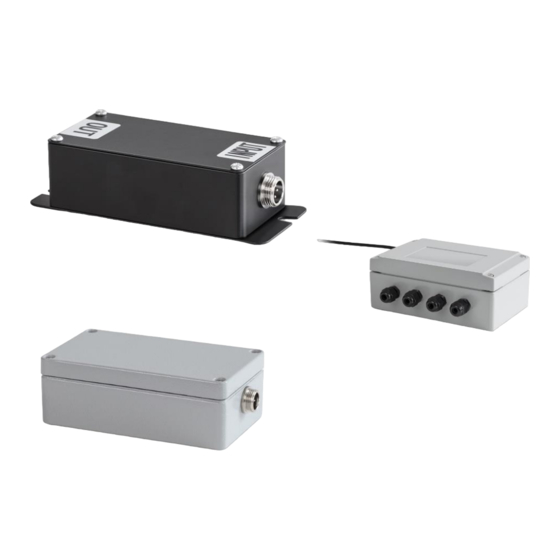
Page 3: Brief Description
After receipt of the device, it should be checked in advance that no transport damage has occurred, that the outer packaging, the plastic housing, other parts or even the device itself have not been damaged. If any damage is evident, please notify SAUTER GmbH immediately. - Page 4 5 Connection 5.1 Sensor 5.1.1 CE WTY1 and CE WTY2 Connection to connector with 5 pins The pins are numbered on the front Connect the 5 wires of the sensor Input + Input - Excitation - Excitation + Shield 5.1.2 CE WTY4 Input + Input - Excitation -...
- Page 5 5.2 Power supply and signal Connect the wires to the appropriate power supply and your evaluation device Power supply 12V or 24V DC depending on model Blue Ground White Signal Depending on model 5.3 Adjust zero point 5.3.1 CE WTY1 and CE WTY2 After connecting the transmitter and load cell, the user could reset the transmitter if it displays incorrectly.
-
Page 6: Declaration Of Conformity
5.4 Settings CE WTY4 Displacement can lead to the failure of the product warranty. W1, W2, W3, W4 can adjust the sensitivity of the sensor output signal. W5 can set the analog output zero point of the voltage. W7 can set the current zero point of the analog output W6 can set the gain of the circuit in the voltage output (0-5V/0~10V) W8 can set the amplification of the circuit in the current output (4-20mA) Note:...