Table of Contents
Advertisement
Quick Links
Advertisement
Table of Contents

Related Manuals for Victron energy EasyPlus


Summary of Contents for Victron energy EasyPlus
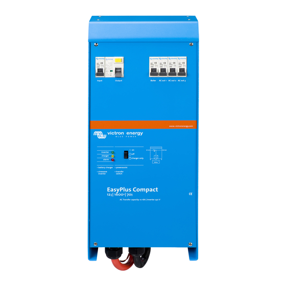
- Page 1 Manual Handleiding Manuel Anleitung Manual EasyPlus 12 | 1600 | 70-16 230V...
- Page 3 EXCEED THE PURCHASE PRICE OF THE VICTRON ENERGY PRODUCTS DESCRIBED HERE IN. Victron Energy B.V. reserves the right to revise and improve its products as it sees fit. This publication describes the state of this product at the time of its publication and may not...
-
Page 5: Safety Instructions
1. SAFETY INSTRUCTIONS General Please familiarize yourself with the safety features and instructions by first reading the documentation supplied with this product before using the equipment. This product has been designed and tested in accordance with international standards. The equipment must be used exclusively for the purpose for which it was designed. -
Page 6: Transport And Storage
Ensure that the equipment is used under the correct ambient conditions. Never operate the product in a wet or dusty environment. Ensure there is adequate free space for ventilation around the product and check that the ventilation vents are not blocked. Ensure that the required system voltage does not exceed the product's capacity. - Page 7 Programmable relay The EasyPlus is equipped with a programmable relay that by default is set as an alarm relay. The relay can be programmed for all kinds of other applications, for example as a starter relay for a...
-
Page 8: Battery Charger
Two outputs to charge 2 battery banks The EasyPlus features 2 outputs, of which 1 can carry the full output current. The second output, limited to approximately 4A and with a slightly lower output voltage, is intended to top up a starter battery. -
Page 9: Operation
If the voltage at the ‘AC-in’ terminal is not within specifications, the inverter will switch on. When the switch is switched to ‘charger only’, only the battery charger of the EasyPlus will operate (if mains voltage is present). In this mode input voltage also is switched through to the ‘AC out’... - Page 10 If a MultiControl panel is connected, on the panel the LEDs ‘bulk’, ‘absorption’ and ‘float’ will also each light during 2 seconds. a. If the switch on the EasyPlus is set to ‘on’ while the ‘Bulk’ LED lights, the charger will switch to equalisation.
-
Page 11: Led Indications
3.4 LED Indications LED off LED flashes LED illuminated Inverter inverter charger The inverter is switched on and supplies power to the load. Battery operation. alarm charger only The inverter is switched on and supplies inverter power to the load. charger Pre alarm: overload, or battery voltage low, or... - Page 12 Charger inverter The AC input voltage is switched through and charger the charger operates in bulk or absorption mode. alarm charger only inverter The AC input voltage is switched through and charger the charger is switched off. The battery charger can not reach battery alarm end voltage (bulk protection mode).
-
Page 13: Installation
4. INSTALLATION This product should be installed by a qualified electrician. 4.1 Location The product must be installed in a dry and well-ventilated area, as close as possible to the batteries. There should be a clear space of at least 10cm around the appliance for cooling. Excessively high ambient temperature will result in the following: Reduced service life. -
Page 14: Connection Of Battery Cables
Connect the battery cables: the + (red) and the - (black), to the battery see appendix A. Reverse polarity connection (+ to – and – to +) will cause damage to the product. (Safety fuse inside the EasyPlus can be damaged) Secure the nuts tightly in order to reduce the contact resistance as much as possible. - Page 15 The solution to this is using an isolation transformer. The mains input & output terminal connector can be found on the bottom of the EasyPlus, see appendix A. The shore or mains cable must be connected to the connector with a three-wire cable.
-
Page 16: Optional Connections
Undo the four screws at the front of the enclosure and remove the front panel. 4.4.1 Second Battery The EasyPlus has a connection (+) for charging a starter battery. For connection see appendix 1 4.4.2 Temperature Sensor The temperature sensor supplied with the product may be used for temperature-compensated charging. - Page 17 DC distribution point must at least equal the sum of the required cross-sections of the connections between the distribution point and the EasyPlus units. - Place the EasyPlus units close to each other, but allow at least 10cm for ventilation purposes under, above and beside the units.
- Page 18 Batteries should be placed in a dry and well-ventilated area during charging. 5.1 Standard settings: ready for use On delivery, the EasyPlus is set to standard factory values. In general, these settings are suitable for single-unit operation. Warning: Possibly, the standard battery charging voltage is not suitable for your batteries!
- Page 19 If search mode is ‘on’, the power consumption in no-load operation is decreased by approx. 70%. In this mode the EasyPlus, when operating in inverter mode, is switched off in case of no load or very low load, and switches on every two seconds for a short period. If the output current exceeds a set level, the inverter will continue to operate.
- Page 20 AES (Automatic Economy Switch) Instead of the search mode, the AES mode can also be chosen (with help of VEConfigure only). If this setting is turned ‘on’, the power consumption in no-load operation and with low loads is decreased by approx. 20%, by slightly 'narrowing' the sinusoidal voltage. Not adjustable with DIP switches.
- Page 21 *In general, the UPS setting can be left ‘on’ if the EasyPlus is connected to a generator with a ‘synchronous AVR regulated alternator’. The UPS mode may have to be set to ‘off’ if the EasyPlus is connected to a generator with a ‘synchronous capacitor regulated alternator’ or an asynchronous alternator.
- Page 22 This energy is used in the evenings and at night. An energy shortfall is compensated by the mains. The EasyPlus converts the battery DC voltage to AC. The power is always less than or equal to the power consumption, so that return delivery to the mains does not occur.
-
Page 23: Configuration By Computer
VE.Bus Quick Configure Setup is a software program with which one EasyPlus unit or systems with a maximum of three EasyPlus units (parallel or three phase operation) can be configured in a simple manner. VEConfigureII forms part of this program. - Page 24 5.5 Configuration with DIP switches Some settings can be changed with DIP switches. Procedure: a) Turn the EasyPlus on, preferably without load and without AC voltage on the inputs. The EasyPlus will then operate in inverter mode. b) Set the DIP switches as required.
- Page 25 ds3-ds4: Setting charge voltages Absorption Absorption Float Storage ds3-ds4 Time Suitable for Voltage Voltage Voltage (hours) Gel Victron Deep dS3=off Discharge dS4=off 14.4 13.8 13.2 Gel Exide A200 (default) AGM Victron Deep Discharge Gel Victron Long Life dS3=on (OPzV) 14.1 13.8 13.2 dS4=off...
-
Page 26: Maintenance
The LEDs ‘charger’ and ‘alarm’ will flash to indicate acceptance of the settings. 6. MAINTENANCE The EasyPlus does not require specific maintenance. It will suffice to check all connections once a year. Avoid moisture and oil/soot/vapours, and keep the device clean. -
Page 27: Troubleshooting Table
Proceed as follows for quick detection of common faults. DC loads must be disconnected from the batteries and the AC loads must be disconnected from the inverter before the inverter and/or battery charger is tested. Consult your Victron Energy dealer if the fault cannot be resolved. Problem Cause... - Page 28 Alt 2: Battery temperature sensor Unplug battery temperature sensor is reached faulty from the EasyPlus. Reset the EasyPlus by switching it off, then wait for 4 seconds and switch it on again If the EasyPlus now charges normally, the battery temperature sensor is...
-
Page 29: Technical Data
8. TECHNICAL DATA EasyPlus 12 Volt PowerControl / PowerAssist Transfer switch (A) ‘Heavy duty’ output AC 0 INVERTER Input voltage range (V DC) 9,5 – 17V Output voltage: 230VAC ± 2% Output AC1,output AC 2,output AC 3 Frequency: 50Hz ± 0,1% (1) Cont. - Page 30 1) Can be adjusted to 60Hz and to 240V 2) Protection a. Output short circuit b. Overload c. Battery voltage too high d. Battery voltage too low e. Temperature too high f. 230VAC on inverter output g. Input voltage ripple too high 3) Non linear load, crest factor 3:1 4) At 25°C ambient 5) Programmable relay which can be set for general alarm, DC undervoltage or genset start signal function...
- Page 31 www.victronenergy.com Appendix A: overview connections Indicator Programmable relay LED illuminates when relay is activated...
- Page 32 Appendix A: overview connections...
- Page 33 www.victronenergy.com Appendix A: overview connections Dipswitch schakelaar Commutateur Dipswitch Dipswitch Schalter Conmutador Dipswitch Ingangs-zekering Disjoncteur entrée Eingangssicherung Disyuntor de entrada Communicatiepoort Port de communication Kommunikationsanschluss Puerto de comunicaciones Temperatuursensor Sonde de temperature Temperaturfühler Sensor de temperatura Alarm contact Contact d’alarme Alarmkontakt Contacto de alarma Accu Minus...
-
Page 34: Appendix B: Installation Information
Appendix B: installation information... - Page 35 www.victronenergy.com Appendix B: installation information Ingangszekering MCB Fusible d;entrée Thermischer Überstrom- Fusible de entrada) Ingang Entrée Netzeingang Entrada Uitgang Sortie Verbracherausgang Salida Aardverbinding naar Liaison à la terre du Verbindung Conexión a tierra de la behuizing boitier Landstromerde / gehäuse carcasa Veiligheidsrelais (AC Relais de sécurité...
-
Page 36: Appendix E: Charge Curve
Battery Safe Mode: If, in order to quickly charge a battery, a high charge current in combination with a high absorption voltage has been chosen, the EasyPlus / EasyPlus will prevent damage due to excessive gassing by automatically limiting the rate of voltage increase once the gassing voltage has been reached.The Battery Safe Mode is part of the calculated absorption time. -
Page 37: Appendix F: Temperature Compensation
www.victronenergy.com 15.0 14.5 14.0 13.5 13.0 Volts Volts 12.5 12.0 11.5 11.0 10.5 10.0 10 15 20 25 30 35 40 45 50 55 60 Battery temperature Default output voltages for Float and Absorption are at 25°C. Reduced Float voltage follows Float voltage and Raised Absorption voltage follows Absorption voltage. - Page 39 www.victronenergy.com...
- Page 40 Serial number: Version : 07 Date : 11 August 2016 Victron Energy B.V. De Paal 35 | 1351 JG Almere PO Box 50016 | 1305 AA Almere | The Netherlands General phone : +31 (0)36 535 97 00 : +31 (0)36 535 97 40 E-mail : sales@victronenergy.com...
Need help?
Do you have a question about the EasyPlus and is the answer not in the manual?
Questions and answers