
Subscribe to Our Youtube Channel
Related Manuals for Victron energy MultiPlus 3000


Summary of Contents for Victron energy MultiPlus 3000
- Page 1 Manual MultiPlus (with firmware xxxx400 or higher) 12 | 3000 | 120 - 50 | 120V 24 | 3000 | 70 - 50 | 120V...
-
Page 3: Safety Instructions
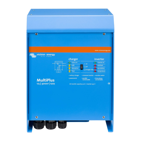
1. SAFETY INSTRUCTIONS In general Please read the documentation supplied with this product first, so that you are familiar with the safety signs en directions before using the product. This product is designed and tested in accordance with international standards. The equipment should be used for the designated application only. - Page 4 2. DESCRIPTION 2.1 In general The basis of the MultiPlus is an extremely powerful sine inverter, battery charger and automatic switch in a compact casing. The MultiPlus features the following additional, often unique characteristics: Automatic and uninterruptible switching In the event of a supply failure or when the generating set is switched off, the MultiPlus will switch over to inverter operation and take over the supply of the connected devices.
-
Page 5: Battery Charger
General Technical Information our website. 2.3 Self consumption – solar energy storage systems For more information see our white paper Self Consumption or Grid independence with the Victron Energy Storage Hub. The appropriate software can be downloaded from our website. -
Page 6: Remote Control
3. OPERATION 3.1 On/Off/Charger Only Switch When switched to "on", the product is fully functional. The inverter will come into operation and the LED "inverter on" will light up. An AC voltage connected to the "AC in" terminal will be switched through to the "AC out" terminal, if within specifications. The inverter will switch off, the "mains on"... - Page 7 3.4 LED Indications LED off LED flashes LED illuminated Inverter Charger Inverter mains on inverter on Bulk overload The inverter is on and supplies power to the load. Absorption low battery charger only Float temperature Charger Inverter mains on inverter on The nominal output of the inverter is Bulk overload...
- Page 8 Charger Inverter mains on inverter on The inverter has switched off due to Bulk overload the electronics temperature being too high. absorption low battery charger only Float temperature Charger Inverter mains on inverter on -If the LEDs are flashing alternately, the battery is nearly exhausted and Bulk overload...
- Page 9 Charger Inverter mains on inverter on The mains voltage is switched Bulk overload through and the charger operates in float mode. absorption low battery charger only Float temperature Charger Inverter mains on inverter on The mains voltage is switched Bulk overload through and the charger operates in equalize mode.
- Page 10 4. Installation This product may only be installed by a qualified electrical engineer. 4.1 Location The product must be installed in a dry and well-ventilated area, as close as possible to the batteries. There should be a clear space of at least 10cm around the appliance for cooling.
- Page 11 4.3 Connection of the AC cabling The MultiPlus is a safety class I product (supplied with a ground terminal for safety purposes). Its AC input and/or output terminals and/or grounding point on the outside of the product must be provided with an uninterruptible grounding point for safety purposes.
- Page 12 4.4 Optional Connections A number of optional connections are possible: 4.4.1 Second Battery The MultiPlus has a connection for charging a starter battery. For connection see Appendix A. 4.4.2 Voltage Sense For compensating possible cable losses during charging, two sense wires can be connected with which the voltage directly on the battery or on the positive and negative distribution points can be measured.
- Page 13 5. Configuration • Settings may only be changed by a qualified electrical engineer. • Read the instructions thoroughly before implementing changes. • During setting of the charger, the AC input must be removed. 5.1 Standard settings: ready for use On delivery, the MultiPlus is set to standard factory values. In general, these settings are suitable for single-unit operation. Warning: Possibly, the standard battery charging voltage is not suitable for your batteries! Refer to the manufacturer's documentation, or to your battery supplier!
- Page 14 Inverter voltage Output voltage of the MultiPlus in battery operation. Adjustability: 95 – 128V Stand-alone / parallel operation / 2-3 phase setting Using several devices, it is possible to: • increase total inverter power (several devices in parallel) • create a split-phase system by stacking (only for MultiPlus units with 120V output voltage) •...
- Page 15 Note: when WeakAC is on, the maximum charge current is reduced by approximately 20%. Not adjustable with DIP switches. BoostFactor Change this setting only after consulting with Victron Energy or with an engineer trained by Victron Energy! Not adjustable with DIP switches. Three programmable relays The MultiPlus is equipped with 3 programmable relays.
- Page 16 5.3 Configuration by computer All settings can be changed by means of a computer or with a VE.Net panel (except for the multi-functional relay and the VirtualSwitch when using VE.Net). The most common settings can be changed by means of DIP switches (see Section 5.5). NOTE: This manual is intended for products with firmware xxxx400 or higher (with x any number) The firmware number can be found on the microprocessor, after removing the front panel.
- Page 17 5.5 Configuration with DIP switches A number of settings can be changed using DIP switches (see appendix A, position M). A number of settings can be changed using DIP switches (see appendix A, position M). Note: When changing settings with DIP switches in a parallel or split-phase/3-phase system one should be aware that not all settings are relevant on all Multis.
- Page 18 Procedure The AC input current limit can be set using DIP switches ds8, ds7 and ds6 (default setting: 50A). Procedure: set the DIP switches to the required value: ds8 ds7 ds6 off = 6,3A on = 10A off = 12A on = 16A off = 20A on = 25A...
- Page 19 5.5.1.5 Examples examples of settings: DS-8 AC input DS-8 DS-8 DS-8 DS-7 AC input DS-7 DS-7 DS-7 DS-6 AC input DS-6 DS-6 DS-6 DS-5 AES DS-5 DS-5 DS-5 DS-4 Ch. current DS-4 DS-4 DS-4 DS-3 Ch. current DS-3 DS-3 DS-3 DS-2 St.-alone mode DS-2 DS-2...
- Page 20 Step 2: Exemplary settings Example 1 is the factory setting (since factory settings are entered by computer, all DIP switches of a new product are set to ‘off’ and do not reflect the actual settings in the microprocessor.). DS-8 Ch. voltage DS-8 DS-8 DS-8...
- Page 21 The MultiPlus does not require specific maintenance. It will suffice to check all connections once a year. Avoid moisture and oil/soot/vapours, and keep the device clean. 7. Error indications With the procedures below, most errors can be quickly identified. If an error cannot be resolved, please refer to your Victron Energy supplier. 7.1 General error indications...
- Page 22 One alarm LED The inverter is switched off due to Check this table for appropriate lights and the alarm activation by the lighted LED. measures in regard to this alarm second flashes. The flashing LED indicates that the state. inverter was about to switch off due to the related alarm.
- Page 23 7.2 Special LED indications (for the normal LED indications, see section 3.4) Bulk and absorption LEDs flash synchronously Voltage sense error. The voltage measured at the voltage sense connection (simultaneously). deviates too much (more than 7V) from the voltage on the positive and negative connection of the device.
- Page 24 3) Switch on all other devices one by one until the error message reoccurs. conjunction with this device. 4) Update the firmware in the last device that was switched on. Should not occur. Switch all equipment off, and then on again. Contact Internal error. Victron Energy if the problem persists.
-
Page 25: Technical Specifications
8. Technical specifications MultiPlus 12/3000/120-50 120V 24/3000/70-50 120V PowerControl / PowerAssist AC input Input voltage range: 95-140VAC; Input frequency: 45 – 65Hz; Power factor: 1 Maximum feed through current (A) Minimum AC supply current capacity for PowerAssist (A) INVERTER Input voltage range (V DC) 9,5 –... - Page 27 APPENDIX A: Overview connections...
- Page 28 AC input (generator input) AC-in-1. Left to right: GROUND (earth), L (phase), N (neutral). 2x RJ45 connector for remote panel and/or parallel and 3-phase operation. AC output AC-out-1. Left to right: L (phase), N (neutral), GROUND (earth). AC output AC-out-2. Left to right: L (phase), N (neutral).
- Page 29 APPENDIX B: Block diagram See table in Chapter 4.2 “Recommended DC fuse”.
- Page 30 APPENDIX C: Parallelconnection SLAVE Unit 3 SLAVE Unit 2 MASTER Unit 1 Panel BAT- BAT- BAT- BAT+ BAT+ BAT+ PE OUT To load AC OUT 1 N AC OUT 1 L To load AC OUT 2 N AC OUT 2 L To load PE IN AC IN...
- Page 31 APPENDIX D: Three-phase connection SLAVE Unit 3 SLAVE Unit 2 MASTER Unit 1 Panel BAT- BAT- BAT- BAT+ BAT+ PE OUT To load AC OUT 1 AC OUT 1 L3 AC OUT 1 L2 AC OUT 1 L1 To load AC OUT 2 AC OUT 2 L3 AC OUT 2 L2...
- Page 32 APPENDIX E: Charge characteristic Charge current 120% 100% Amps Time Volts Charge voltage Time 4-stage charging: Bulk Entered when charger is started. Constant current is applied until nominal battery voltage is reached, depending on temperature and input voltage, after which constant power is applied up to the point where excessive gassing is starting (14.4V resp. 28.8V, temperature compensated). Battery Safe The applied voltage to the battery is raised gradually until the set Absorption voltage is reached.
- Page 33 APPENDIX F: Temperature compensation 15.0 14.5 14.0 13.5 13.0 Volts Volts 12.5 12.0 11.5 11.0 10.5 10.0 10 15 20 25 30 35 40 45 50 55 60 Battery temperature Default output voltages for Float and Absorption are at 25°C. Reduced Float voltage follows Float voltage and Raised Absorption voltage follows Absorption voltage.
- Page 34 APPENDIX G: Dimensions...
- Page 38 Version : 14a Date : August 28 , 2017 Victron Energy B.V. De Paal 35 | 1351 JG Almere PO Box 50016 | 1305 AA Almere | The Netherlands General phone +31 (0)36 535 97 00 +31 (0)36 535 97 40 E-mail sales@victronenergy.com...
Need help?
Do you have a question about the MultiPlus 3000 and is the answer not in the manual?
Questions and answers