Viessmann VITOTRONIC 300-K Operating Instructions Manual
Hide thumbs
Also See for VITOTRONIC 300-K:
- Installation and service instructions manual (164 pages) ,
- Operating instructions manual (48 pages) ,
- Operating instructions for the system user (52 pages)

Related Manuals for Viessmann VITOTRONIC 300-K


Summary of Contents for Viessmann VITOTRONIC 300-K
- Page 1 VIESMANN Operating instructions for the system user Multi boiler system with weather-compensated cascade control Vitotronic 300-K, type MW2C VITOTRONIC 300 Please keep safe. 5546 498 CA 6/2015...
- Page 2 Safety instructions For your safety Please follow these safety instructions closely to ■ Never remove casings. prevent accidents and material losses. ■ Never change or remove attachments or fitted accessories. Safety instructions explained Never open or retighten pipe connections. ■ Danger Danger This symbol warns against the risk of injury.
-
Page 3: For Your Safety
Safety instructions For your safety (cont.) What to do if water escapes from the appliance Extractors Danger The operation of appliances that extract air to the out- When water escapes from the appliance there is side (cooker hoods, extractors, air conditioning units, a risk of electrocution. - Page 4 Energy saving tips ................. Tips for greater comfort ................. 3. Operation Where to find the controls ..............Vitotronic 200 ..................■ Opening the Vitotronic 300-K ..............Cascade control unit programming unit ..........Default display ..................10 ■ Main menu ..................10 ■...
- Page 5 Index Index (cont.) Setting the display backlighting ............. 24 Naming heating circuits ................. 24 Setting the time and date ............... 25 Setting the language ................25 Setting measuring units ................. 25 Restoring factory settings ..............26 8. Scanning Scanning information ................27 Scanning the solar energy yield in conjunction with solar thermal ■...
-
Page 6: Intended Use
Information Symbols Symbol Meaning Reference to other document containing further information Step in a diagram: The numbers correspond to the order in which the steps are carried out. Warning of material losses and environ- mental pollution Live electrical area Pay particular attention. Component must audibly click into place. -
Page 7: Introductory Information
Introductory information Commissioning The commissioning and matching of the control unit to As the user of new combustion equipment, you may be local conditions and building characteristics, as well as obliged to notify your local flue gas inspector of the instructing the user in the operation of the system, installation [check local regulations]. -
Page 8: Tips For Greater Comfort
Introductory information Energy saving tips (cont.) ■ Holiday: DHW heating If you are going away, select the "Holiday pro- gram": DHW circulation pump: ■ The room temperature will be reduced, and DHW Activate the DHW circulation pump only for periods heating will be turned off. -
Page 9: Where To Find The Controls
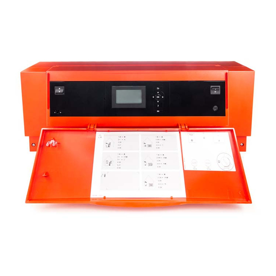
Opening the Vitotronic 300-K The programming unit is located behind cover flap To open, pull the top edge of the hinged cover forward. -
Page 10: Default Display
Operation Cascade control unit programming unit (cont.) Default display In the default display, the number of boilers installed in Boiler operating mode the heating system is shown in a specific order (boiler sequence). You can change the boiler sequence (see The flame symbol indicates the current boiler heating page 24). - Page 11 Operation Cascade control unit programming unit (cont.) Calls up fault or service messages. Scrolls through the menu.
-
Page 12: Without Frost Protection Monitoring (Shutdown)
Start-up/shutdown Switching on the heating system Cascade Fig. 6 ON/OFF switch Fault indicator (red) MCB/fuse Emissions test switch ON indicator (green) (only for servicing purposes) Ask your heating contractor about the following: 2. Open the gas shut-off valve on every boiler. ■... - Page 13 Start-up/shutdown Shutting down the heating system (cont.) Information on a prolonged shutdown ■ Circulation pumps may seize up as they are not being supplied with power. It may be necessary to reset the date and time (see ■ page 25).
-
Page 14: Special Operating Programs
Central heating Operating program Operating programs for central heating, DHW, frost protection Symbol Operating program Function "Heating and DHW" The rooms of the selected heating circuit are ■ heated in accordance with the room temperature and time program specified (see chapter "Central heating"). -
Page 15: Central Heating
Central heating Time program (cont.) Setting time phases Example: 08. + for time phase 2 Time program for "Monday" ■ ■ Time phase 1: / for the start and end point of time phase 2. The 05:30 to 09:00 h bar in the time diagram is adjusted. - Page 16 Central heating Time program (cont.) 6. "Copy" 8. Press OK to confirm Heating circuit 1 heating time program Heating circuit 1 heating time settings for Monday Accept for the following days: Copy Change Fig. 10 Fig. 11 7. "Tu" , "We", "Th", "Fr" Changing time phases For Tuesday you want to change the start point of / for the start point of time phase 2 on.
-
Page 17: Room Temperature
Central heating Time program (cont.) Heating circuit 1 heating time settings for Wednesday from Fig. 13 Room temperature Further information can be found in chapter "Terminology" in the Appendix. Setting standard room temperature for the selected heating circuit Factory setting: 20 °C 3. -
Page 18: Setting The Heating Curve
Central heating Operating program (cont.) 2. "Heating" 5. Press OK to confirm 3. "Heating circuit 1", "Heating circuit 2" or "Heat- For information on the operating programs, see ing circuit 3" as the required heating circuit page 14 4. "Operating program" Time program Further information can be found in chapter "Terminology"... -
Page 19: Stopping Central Heating
Central heating Heating curve (cont.) Depending on various outside temperatures (shown on the horizontal axis), the assigned set flow tempera- tures for the heating circuit are highlighted in white. Stopping central heating Tap the following buttons: 4. "Operating program" 1. "Menu" 5. - Page 20 Central heating Comfort function "Comfort mode" (cont.) ■ Automatically when the system switches to standard heating mode in accordance with the time program Automatically after 8 hours ■ Note If you want to make changes to this, contact your local heating contractor. Energy saving function "Economy mode"...
- Page 21 Central heating Energy saving function "Holiday program" Setting "Holiday program" Note / for "Departure date" and "Return date" The holiday program affects all heating circuits. If you want to make changes to this, contact your local 6. Press OK to confirm heating contractor.
- Page 22 DHW heating DHW temperature Factory setting: 50 °C 3. "DHW temperature" Setting range: 10 to 60 °C for the required value Tap the following buttons: 5. Press OK to confirm 1. "Menu" 2. "DHW" Operating program Further information can be found in chapter "Terminology"...
-
Page 23: Stopping Dhw Heating
DHW heating Time program (cont.) Set time phase 4 for this. During this time, DHW will be Note heated to the second set DHW temperature value. ■ A start and stop time must be set for the 2nd and 3rd time phase. -
Page 24: Setting The Display Backlighting
Further adjustments Setting the boiler sequence Depending on the parameters set and internal control 4. Press OK to confirm calculations, the control unit offers various boiler sequences. This ensures that the boilers are equally The diagram shows the following boiler sequence: loaded. -
Page 25: Further Adjustments
Further adjustments Naming heating circuits (cont.) 5. Press OK to confirm Control keyboard The name assigned for each heating circuit appears in the main menu. Renaming heating circuit 1 Htg circ. selection ü ö ä Heating circuit 3 Ground floor Heating circuit 2 Fig. - Page 26 Further adjustments Restoring factory settings You can individually restore all modified values for 3. "Factory settings" each heating circuit to their factory setting. 4. "Heating circuit 1", "Heating circuit 2" or "Heat- Tap the following buttons: ing circuit 3" as the required heating circuit 1.
-
Page 27: Scanning Information
Scanning Scanning information Subject to the components connected and the settings Note made, you can scan current temperatures and operat- If heating circuits have been named (see chapter ing conditions. "Naming heating circuits") the assigned name is dis- played. Information in the main menu is split into groups: For detailed scanning options on individual groups see ■... -
Page 28: Resetting Data
Scanning Scanning information (cont.) Resetting data You can reset the following data: 2. "Information" ■ In conjunction with a solar thermal system: Solar energy yield, solar circuit pump hours run and 3. "Reset data" hours run output 22. All the above data simultaneously. 4. - Page 29 Scanning Scanning fault messages (cont.) Calling up a fault message Message list 1. Tap in the footer. The fault message appears in a list. Service messages Faults Faults Time Text Help 11:30 AM f0: Burner control unit 24/06/2014 Fig. 25 Tap "Faults"...
- Page 30 Emissions test mode Emissions test mode Emissions test mode for testing flue gas with briefly raised boiler water temperature. Emissions test mode should be activated only by your flue gas inspector, during the annual inspection. 1. Set the emissions test switch on the Vitotronic 300- K (see chapter "Starting the heating system") to position The following functions are activated:...
-
Page 31: Rooms Are Too Cold
What to do if... Rooms are too cold Cause Remedy The heating system is off. Switch ON the ON/OFF switch on the control units ■ (see page 12). Switch ON the mains isolator, if installed (outside the ■ boiler room). Set the MCB on the power distribution board (main ■... -
Page 32: There Is No Hot Water
What to do if... There is no hot water Cause Remedy The heating system is off. Switch ON the ON/OFF switch on the control units ■ (see page 12). Switch ON the mains isolator, if installed (outside the ■ boiler room). Set the MCB on the power distribution board (main ■... -
Page 33: Inspection And Maintenance
Maintenance Cleaning The appliances can be cleaned with any commercially available domestic cleaning agent (non-scouring). Clean the surface of the programming unit with the microfibre cloth provided. Inspection and maintenance The inspection and maintenance of a heating system Regular maintenance ensures trouble-free, energy effi- is prescribed by the Energy Saving Ordinance [EnEV - cient, environmentally responsible and safe heating. - Page 34 Damaged cables / lines If there is damage to the connecting cables or lines of the appliance or externally installed accessories, these must be replaced with special cables or lines. Use only Viessmann cables/lines as replacement. For this, con- tact your qualified contractor.
-
Page 35: Overview Of Extended Menu
Appendix Overview of extended menu Menu Boiler sequence Heating Solar energy Solar energy yields DHW temperature Information DHW time program Time program DHW circulation Service Settings General For detailed Comfort mode call up Heating circuit 1 Economy mode options: Heating circuit 2 Set room temperature See following Heating circuit 3... - Page 36 Appendix Scanning options under "Information" (cont.) Heating circuit 1, 2, 3 "Operating program" "DHW time prog" "Screed drying" "DHW circ time prog" ■ "Remote device connected" ■ "DHW temp." "Holiday program" ■ "External program" ■ In conjunction with 2 cylinder temperature sensors: "Comfort mode"...
- Page 37 Appendix Terminology (cont.) The screed drying function affects heating circuits with The room temperature is captured and transmitted to mixer: the control unit by a sensor. The sensor is fitted in the All rooms are heated according to the temperature/ room.
- Page 38 Appendix Terminology (cont.) Slope -5 -10 -15 -20 Outside temperature in °C Fig. 27 Example: Heating circuit For outside temperature 14 °C: − Underfloor heating system, slope 0.2 to 0.8 A heating circuit is a sealed unvented circuit between Low temperature heating system, slope 0.8 to 1.6 the boiler and radiators, through which the heating Heating system with a boiler water temperature in water circulates.
-
Page 39: Final Decommissioning And Disposal Of The Heating System
(Altstoff Recycling Austria AG, licence num- ber 5766). Final decommissioning and disposal of the heating system Viessmann products can be recycled. Components Please contact your heating contractor regarding the and fluids from your heating systems do not belong in correct disposal of your old system. - Page 40 Appendix Information on disposal (cont.) DE: Operating fluids (e.g. heat transfer medium) can be disposed of at municipal collection points. AT: Operating fluids (e.g. heat transfer medium) can be disposed of at municipal collection points (ASZ).
- Page 41 Keyword index Keyword index Energy saving function Actual temperature scanning........27 – Holiday program............21 Appliance, starting............12 Extension kit...............36 External hook-up............14 External program............14 Boiler sequence, setting..........24 Brightness, setting............24 Factory setting..............7 Fault display............... 32 Central heating Fault message – Factory setting............7 –...
- Page 42 Keyword index Keyword index (cont.) Maintenance contract..........33 Scanning options............35 Menu structure............35 Screed drying............. 14 Service............... 32 Service address............27 Names for heating circuits..........24 Service message Night setback............. 38 – Calling up (acknowledged)........28 No hot water...............32 – Scanning..............28 Notice of completion.............7 Setback mode............
-
Page 43: Keyword Index
Keyword index Keyword index (cont.) Where to find the controls..........9 Underfloor heating............37 Window ventilation............8 Winter mode...............36 Wintertime/summertime changeover......7 Water too cold............32 Wintertime changeover..........7 Water too hot..............32 Weather-compensated mode........39... -
Page 44: Your Contact
Your contact Contact your local contractor if you have any questions regarding the maintenance and repair of your system. You may, for example, find local contractors on the internet under www.viessmann.com. Viessmann Werke GmbH&Co KG Viessmann Limited D-35107 Allendorf Hortonwood 30, Telford...
Need help?
Do you have a question about the VITOTRONIC 300-K and is the answer not in the manual?
Questions and answers