Table of Contents
Advertisement
Quick Links
Electric Pressure Pump and Controller
Dear user,
We have made every effort to ensure the accuracy of the contents of this
manual. Should any errors be detected, we would greatly appreciate to
receive suggestions to improve the quality of the contents of this manual.
For more detailed technical data about Beamex ePG Electric Pressure
Pump and Controller, please contact the manufacturer.
ePG
© Beamex 2022
Beamex Oy Ab
Ristisuonraitti 10
FIN-68600 Pietarsaari
Finland
Tel:
E-mail:
Internet:
8805000 / ePGuEng / Version 1.0
+358-10-5505000
sales@beamex.com
service@beamex.com
https://www.beamex.com
Advertisement
Table of Contents

Related Manuals for BEAMEX ePG


Summary of Contents for BEAMEX ePG
- Page 1 Should any errors be detected, we would greatly appreciate to receive suggestions to improve the quality of the contents of this manual. For more detailed technical data about Beamex ePG Electric Pressure Pump and Controller, please contact the manufacturer.
-
Page 2: Table Of Contents
Safety..................6 Approvals................... 6 Symbols Used on the device.............6 Operating Environment and Specifications........6 Safety Precautions and Warnings............. 9 General Warnings Concerning Pressure Measurement....10 About ePG................11 General.....................11 Top view...................12 Battery Pack..................13 Operating instructions............15 Setting Up..................15 User Interface and Functionality............16 Troubleshooting.............. -
Page 3: Prologue
Beamex ePG is a portable, hand-held, battery-powered device that is used to generate reference pressure in pressure calibration applications. With ePG you can generate pressure between -0.85 to 20 bar / -12.4 to 300 psi. Since the device does not have a display to indicate the generated pressure reading, it must be connected to an external pressure device with an appropriate display, e.g. - Page 4 (see chapter Service and transportation instructions). Include a detailed description of the reason for the return. ePG is available in two different configurations with different delivery contents: ePG Pump Only (9021000) • ePG with a hand strap • Battery pack (8006030) •...
-
Page 5: Feedback
• Set of Mesh filters for the output connector (8006160, 5 pcs) • Set of Adhesive Vents (8006165, 3 pcs) • ePG Piston Seal Service kit: piston seals and cylinder's o-ring (8006130) • ePG Cylinder Service kit: cylinder and o-ring (8006140) •... -
Page 6: Safety
6 - Safety Safety Approvals All available approvals and declaration of conformity can be downloaded from Beamex's website. Symbols Used on the device Caution! Please read the manual for further information Operating Environment and Specifications Warning: Only use the device for purposes and in environments specified in the user manual. - Page 7 Technical drawing. Weight ~ 2.3 kg / ~ 5 lb Pressure Ports G1/8" (ISO228/1) female port with adapter for Beamex low pressure hose Filter Elements A filter element (36 micron) included in the pressure port Pressure Media Clean dry non-corrosive gases...
- Page 8 0 to 40 °C / 32 to 104 °F from 40 °C to 50 °C / 104 to 122 °F ≤ 50 %RH ePG will work at higher humidity, but its performance may drop Note: If the device has been stored in different environment it should be stabilized to the new environment before use.
-
Page 9: Safety Precautions And Warnings
Warning: Only personnel with good experience and knowledge of pressure media, pressure instruments and connections are allowed to work with ePG. Incorrect use may result in damage to the device, the instrument connected to it and/or personal injury. Warning: Use only the pressure measurement T-hose delivered by Beamex, marked with "Max. -
Page 10: General Warnings Concerning Pressure Measurement
Warning: Do not use Teflon (PTFE) tape to seal anything in the device. Warning: Do not use ePG in any other way than as described in this manual. General Warnings Concerning Pressure Measurement Warning: Always depressurize the system before opening or connecting any pressure fittings or connectors. -
Page 11: About Epg
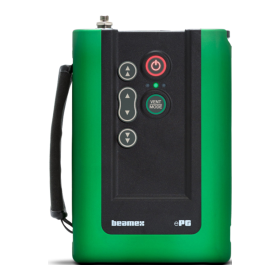
About ePG - 11 About ePG General Figure 2: Overview presents a general view of ePG, its parts and its buttons' functionality. Figure 2: Overview Legend: Pressure Output Connector Lithium-ion Battery Pack Power Button... -
Page 12: Top View
Vent / Mode Button Shoulder Strap Hook Operation buttons for pressure/vacuum generation Top view Figure 3: ePG, top view Legend: USB-C port, for charging the Battery Pack and software updates Locking mechanism, when locked, prevents the battery pack from falling out... -
Page 13: Battery Pack
About ePG - 13 Battery Pack Figure 4: Battery Pack locked When the slot is in a vertical position the Battery Pack is locked. Figure 5: Battery Pack unlocked To unlock the Battery Pack, turn the slot to the right (in horizontal position). - Page 14 45 °C / 32 °F to 113 °F) the battery pack cannot be charged. Also if the internal temperature is over 60 °C / 140 °F, ePG stops working automatically as a precaution until the temperature is again within limits.
-
Page 15: Operating Instructions
Operating instructions - 15 Operating instructions Setting Up Connect one of the three ends of the T-pressure hose to the ePG's output connector. Connect one of the remaining open ends to the calibrator's / pressure measuring device's input connector. Connect the last open end to DUT's* input connector. -
Page 16: User Interface And Functionality
You can operate the ePG by pressing the buttons on the device. Figure 7: Buttons on the device Figure 8: Power button ePG is powered on by pressing the Power button. This is indicated by Power button lighting up. When powered on, the device goes automatically into vent mode. This is indicated by green LED blinking. - Page 17 Operating instructions - 17 Figure 9: Vent / Mode button Vent / Mode button is used to vent the ePG or change the mode from pressure to vacuum and vice versa. When pressed, the ePG goes into vent mode which is indicated by the green LED blinking.
- Page 18 The button can be either clicked or pressed and held. When it is clicked, the ePG decreases pressure in bigger steps (~ 100 to 200 mbar / 1.45 to 2.90 psi per step). When it is pressed and held, the...
- Page 19 After locking you can lift your fingers from the buttons. Locking can be released by pressing any of the the arrow buttons. Then the ePG holds the generated pressure and waits for further instructions. Please notice, that if the Power or Vent / Mode button is pressed to...
-
Page 20: Troubleshooting
2. The yellow LED is blinking and 2. There might be a major fault in the Power button is very bright. ePG. Power the ePG off and on to check if the fault disappears. If the fault indication reappears, send... - Page 21 (see Table 1: Specifications table). ePG does not start even if the battery is full. INDICATION SOLUTION ePG feels very warm. Let the ePG temperature return to normal. When the internal temperature rises >...
-
Page 22: Maintenance
Note: Please notice that the ePG must be in the Pressure mode during drying procedure. • If any parts of ePG require cleaning, use a cloth damped with a water- based or alcohol-based solvent. Alternatively, use low concentration of hydrogen peroxide or mild solution of mild soap water. Never use any strong detergents. -
Page 23: Cleaning The Output Valve
Maintenance - 23 Cleaning The Output Valve Unscrew all the screws from the back cover. Be aware of the one screw located in battery compartment (1). Figure 14: Step 1 Gently lift the back cover and make sure that the main PCB stays in its place in the front cover. - Page 24 24 - Maintenance Unscrew the two screws (1) from the valve cover (2). Figure 16: Step 3 Remove the valve cover. Figure 17: Step 4...
-
Page 25: Changing The Non-Return Valve Package
Valve from sliding inside the cylinder. Figure 18: Step 5 Changing The Non-return Valve Package ePG Non-return valve service kit is available (8006145). Remove the back cover and case gasket (see steps 1-5 in chapter Cleaning The Output Valve). Manually turn the Piston Assembly in lower position so that you can see the screw (1) behind the Cylinder Guiding End (2) and unscrew it. - Page 26 26 - Maintenance Unscrew the following two screws (1) from the pump mechanism and lift the whole mechanism slightly up. Figure 20: Step 3 Unscrew the four screws holding the cylinder ends together. When reassembling, tighten the screws with 2.5 Nm of torque. Figure 21: Step 4...
- Page 27 Maintenance - 27 When the screws are unscrewed, lift the Guiding End and the cylinder (1). Before lifting the cylinder, push it slightly backwards and turn it a bit to the right so it can be easily lifted up. Be careful not to slide the cylinder downwards in a way that the piston seal comes visible from the top of the cylinder.
-
Page 28: Changing The Piston Seals
Figure 24: Step 7 Assemble the device in the opposite order. Changing The Piston Seals ePG Piston Seal Service kit is available (8006130). Remove the back cover and case gasket (see instructions in chapter Cleaning The Output Valve). Follow the steps 2 - 5 described in chapter... - Page 29 Maintenance - 29 Remove guiding end and cylinder. Figure 25: Step 3 Unscrew the M3x6 screw (1), remove the Piston Top, Piston Seal (2) and Guiding Ring (3). Open up or break the Guiding Ring for example with a screwdriver so that the Guiding Ring can be changed. Figure 26: Step 4 All the parts removed.
- Page 30 30 - Maintenance Push and slide the new Guiding Ring (1) over the replacement tool (2). The Guiding Ring is tight and because of that you need to use a tool to get it in place. Figure 28: Step 6 Push the Guiding Ring and the replacement tool against the piston.
-
Page 31: Changing The Adhesive Vent
Changing the Adhesive Vent Set of Adhesive Vents (8006165, 3 pcs). Adhesive Vents equalize pressure inside sealed enclosures. ePG's Adhesive Vent can be found on the bottom of the battery compartment. Adhesive Vent should be replaced when it has become loose or dirty. -
Page 32: Firmware Update
32 - Maintenance Firmware update Check for ePG firmware updates at the Download Center (https:// www.beamex.com/download%20center). Please read the instructions and the accompanying release note carefully. Follow the instructions to update the firmware version. -
Page 33: Related Products
Related Products - 33 Related Products There is an increasing number of devices that can be used together with ePG. The following list includes devices that are already available (valid when this manual was printed): • Beamex MC2/4 family calibrators •... -
Page 34: Disposal Of Waste Electrical And Electronic Equipment
Disposal of Waste Electrical and Electronic Equipment Beamex and WEEE Beamex is an environmentally conscious company developing products with a view to ensure that they are easy to recycle and do not introduce hazardous materials into the environment. In the European Union (EU) and other countries with separate collection systems, waste from electrical and electronic equipment (WEEE) is subject to regulations. -
Page 35: Service And Transportation Instructions
You can perform basic maintenance (e.g. changing the seals and non- return valves) by yourself. More complex maintenance and repairs must only be performed by Beamex's service team or an authorized representative. When sending ePG for service, place it in its original package, as received upon the delivery from Beamex.
Need help?
Do you have a question about the ePG and is the answer not in the manual?
Questions and answers