Table of Contents
Advertisement
Available languages
Available languages
Quick Links
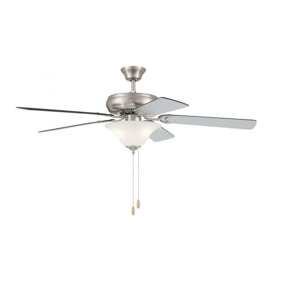
Decorator's Choice
Installation Guide
For Models:
DCF52XXX5C1W
4007498
net weight of fan: 16.2 lb. (7.35 kg)
READ THESE INSTRUCTIONS AND
Table of Contents:
Safety Tips. pg. 2
Unpacking Your Fan. pg. 3
Parts Inventory. pg. 3
Installation Preparation. pg. 4
Hanging Bracket Installation. pg. 4
Fan Assembly. pgs. 5 - 6
Wiring. pg. 7
Canopy Assembly. pg. 7
Blade Assembly. pg. 8
Testing Your Fan. pg. 10
Troubleshooting. pg. 11
Parts Replacement. pg.11
Warranty. pg. 11
page 1
SAVE THEM FOR FUTURE USE
PRINTED IN CHINA
Advertisement
Table of Contents

Related Manuals for Craftmade DCF52 5C1W Series


Summary of Contents for Craftmade DCF52 5C1W Series
-
Page 1: Table Of Contents
READ THESE INSTRUCTIONS AND SAVE THEM FOR FUTURE USE Decorator’s Choice Installation Guide For Models: DCF52XXX5C1W Table of Contents: Safety Tips. pg. 2 Unpacking Your Fan. pg. 3 Parts Inventory. pg. 3 Installation Preparation. pg. 4 Hanging Bracket Installation. pg. 4 Fan Assembly. -
Page 2: Safety Tips
(2) this LED light kit must accept any interference received, including interference that may cause undesired operation. Distributed by: Craftmade, 3901 S. 20th Avenue, DFW Airport, TX, 75261; 1-800-486-4892 NOTE: The important safety precautions and instructions appearing in the manual are not meant to cover all possible conditions and situations that may occur. -
Page 3: Unpacking Your Fan
1. Unpacking Your Fan. Carefully open the packaging. Remove items from Styrofoam inserts. Remove motor housing and place on carpet or Styrofoam to avoid damage to finish. Do not discard fan carton or Styrofoam inserts should this fan need to be returned for repairs. -
Page 4: Installation Preparation
3. Installation Preparation. blade edge To prevent personal injury and damage, ensure that inches the hanging location allows the blades a clearance of 7 feet (76cm) 7ft. (2.13m) from the floor and 30in. (76cm) from any (2.13m) wall or obstruction. This fan is suitable for room sizes up to 400 square 12ft. - Page 5 5. Fan Assembly (with downrod). stop pin set screw Remove hanging ball from downrod provided by loosening set screw on hanging ball. Remove pin hanging ball and clip. Lower hanging ball and remove stop pin. Then slide hanging ball off downrod. [Refer to diagram 1.] clip diagram 1...
-
Page 6: Fan Assembly. Pgs
5. Fan Assembly (with downrod). (cont.) With the hanging bracket secured to the outlet box and able to support the fan, you are now ready to hang your fan. Grab the fan firmly with two hands. Slide downrod through opening in hanging bracket and let hanging ball rest on the hanging bracket. -
Page 7: Wiring
7. Wiring. WARNING: Turn off circuit breakers to current fixture from breaker panel and be sure switch is white supply wire ground turned to the OFF position. (green or bare) black supply wire CAUTION: Be sure outlet box is properly grounded and that a ground wire (GREEN or Bare) is present. -
Page 8: Blade Assembly
9. Blade Assembly. blade screw and washer WARNING: To reduce the risk of serious bodily injury, DO NOT use power tools to assemble the blades. If screws are overtightened, blades may crack and motor housing break. Tip: Break apart fiber washers from set and blade attachment then place one washer on each blade screws and washers... -
Page 9: Light Kit Assembly (Optional). Pgs
motor housing 10. Light Kit Assembly (Optional). Remove 3 screws from switch housing cap. [Refer to diagram 1.] If you wish to use fan WITHOUT the light switch housing kit, align holes in switch housing cap with holes in switch housing. [Note: The gap on the top edge of the switch housing cap must align with the reverse switch on the switch housing... -
Page 10: Testing Your Fan
10. Light Kit Assembly (Optional). (cont.) Remove finial, finial plate, hex nut, flat washer switch and rubber washer from threaded rod at housing bottom of light kit fitter. Place rubber washer motor housing inside shade over center hole. Raise shade in order to guide pull chains through appropriate holes in shade. -
Page 11: Troubleshooting
Service at 1-800-486-4892 to arrange for return of fan. 1. Check wall switch to fan. Return fan, shipping prepaid, to Craftmade. We will repair 2. Verify that reverse switch is set completely in or ship you a replacement fan, and we will pay the return shipping cost. - Page 12 LEER ESTAS INSTRUCCIONES Y GUARDARLAS PARA UTILIZACIÓN FUTURA Decorator’s Choice Guía de instalación Para modelos: DCF52XXX5C1W Índice de materias: Sugerencias de seguridad. Pág. 2 Desempaquetado del ventilador. Pág. 3 Inventario de piezas. Pág. 3 Preparación para la instalación. Pág. 4 Instalación del soporte de montaje.
- Page 13 Distribuido por: Craftmade, 3901 S. 20th Avenue, DFW Airport, TX, 75261; 1-800-486-4892 NOTA: No se debe concluir que las precauciones de seguridad importantes e instrucciones en este manual van a abarcar todas las condiciones y situaciones posibles que puedan ocurrir.
- Page 14 1. Desempaquetado del ventilador. Abrir el empaque cuidadosamente. Sacar los artículos del embalaje. Sacar el motor y ponerlo en una alfombra o en el embalaje para evitar rayar el acabado. Guardar la caja de cartón o el empaquetamiento original en caso de que tenga que mandar el ventilador para alguna reparación.
- Page 15 3. Preparación para la instalación. borde del aspa Para prevenir daño corporal y otros daños, estar seguro 76cm de que el lugar en donde va a colgar el ventilador le permite un espacio libre de 2,13m (7 pies) entre las 2,13m pulg.) puntas de las aspas y el piso y 76cm (30 pulg.) entre las...
- Page 16 5. Ensamblaje del ventilador (con tubo). tornillo Quitar la bola que sirve para colgar del tubo provisto perno de tope de fijación aflojando el tornillo de fijación de la bola que sirve para colgar. Quitar el perno y la clavija. Bajar la bola que sirve para colgar y sacar el perno de tope.
- Page 17 5. Ensamblaje del ventilador (con tubo). (cont.) Ya que esté sujetado el soporte de montaje a la caja de salida y capaz de apoyar el ventilador, usted está listo para colgar el ventilador. Agarrar el ventilador firmemente con las dos manos.
- Page 18 7. Instalación eléctrica. ADVERTENCIA: Apagar los cortacircuitos en el panel de electricidad que suplen corriente a la caja de salida y alambre conductor blanco toma de tierra asegurarse de que el interruptor de luz esté APAGADO. (verde o pelada) alambre conductor negro PRECAUCIÓN: Asegurarse de que la caja de salida esté...
- Page 19 9. Colocación de las aspas. ADVERTENCIA: Para reducir el riesgo de tornillo para el aspa y arandela lesiones corporales graves, NO utilizar herramientas eléctricas para ensamblar las aspas. Si aprieta demasiado los tornillos, las aspas podrían agrietarse y quebrarse. bastidor del motor Consejo: Separar las arandelas de fibra para luego poner una arandela en cada tornillos y arandelas...
- Page 20 10. Instalación del juego de luz (opcional). bastidor del motor Quitar los 3 tornillos de la cubierta de la caja de encendido. [Referirse al diagrama 1.] Si desea utilizar el ventilador SIN el juego de luz, alinear los agujeros en la cubierta de la caja de encendido con los agujeros en la caja de encendido.
- Page 21 10. Instalación del juego de luz (opcional). (cont.) Quitar el adorno con rosca, la placa del adorno con rosca, caja de la tuerca hexagonal, la arandela plana y la arandela de encendido hule de la varilla roscada en la parte inferior del bastidor del motor conectador para el juego de luz.
- Page 22 2. Verificar que se instalaron correctamente las y Craftmade pagará los gastos de envío de regreso. bombillas. GARANTÍA LIMITADA DE 6 AÑOS hasta DE POR VIDA: 3. Verificar que se hizo correctamente la conexión de CRAFTMADE reparará...
Need help?
Do you have a question about the DCF52 5C1W Series and is the answer not in the manual?
Questions and answers