
Subscribe to Our Youtube Channel
Related Manuals for Oriental motor EZ limo ESMC-K2


Summary of Contents for Oriental motor EZ limo ESMC-K2
- Page 1 (217) 352-9330 | Click HERE Find the Oriental Motor ESMC-K2 at our website:...
- Page 2 ESMC-K2 ESMC-A2 ESMC-C2 OPERATING MANUAL Thank you for purchasing an Oriental Motor product. This Operating Manual describes product handling procedures and safety precautions. Please read it thoroughly to ensure safe operation. • Always keep the manual where it is readily available.
-
Page 3: Table Of Contents
Table of contents 1 Introduction..........3 5 Timing charts .......... 38 Important note ..........3 Return-to-home operation (common to the controller and driver modes) ......38 Overview of the product........3 Positioning operation System configuration ........3 (controller mode only) ........39 Compliance with the EC Directives .... -
Page 4: Introduction
1 Introduction 1 Introduction 1.1 Important note Be sure to confirm that the motorized actuator model shown on the controller key is the same as the model of the motorized actuator connected to the controller. If the two numbers do not match, the motorized actuator cannot be operated according to the specification. -
Page 5: Compliance With The Ec Directives
1 Introduction 1.4 Compliance with the EC Directives The controllers bear the CE Marking indicating their compliance with the Low Voltage and EMC Directives, based on combinations with the products specified below. The controllers do not comply with the EC Directives if combined with other products. •... - Page 6 1 Introduction EMC Directive Provide EMC measures when installing/wiring the product. Without effective measures to suppress EMI (electromagnetic interference) caused by the motorized actuator, controller or teaching pendant in the surrounding control systems equipment and to address EMS (electromagnetic susceptibility) of the motorized actuator, controller or teaching pendant, the machine’s performance may be severely affected.
-
Page 7: Names And Functions Of Front Panel
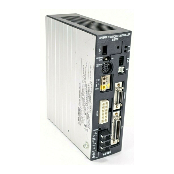
1 Introduction 1.5 Names and functions of front panel • ESMC-K2 • ESMC-A2, ESMC-C2 Controller key Controller key POWER LED POWER LED ALARM LED ALARM LED Pendant switch Pendant switch Mode switch Mode switch Pendant connector Pendant connector Battery Battery Logic power connector Logic power... -
Page 8: Controller Key
1 Introduction 1.6 Controller key A controller key corresponding to the combined motorized actuator is installed on the controller. (If you have purchased a controller only, no controller key is supplied.) Controller key Motorized actuator model The controller key stores data relating to motorized actuator control. The controller uses these data to automatically set the following parameters in accordance with the specification of the combined motorized actuator: I/O parameter:... -
Page 9: Installation
2 Installation 2 Installation 2.1 Controller clearances required at installation Install the controller on a vertical, flat surface inside an enclosure placed indoors. If the controller is not installed vertically, heat generated from the controller will not be Note radiated properly and the controller may be damaged due to excessive heat. Top: 20 mm (0.79 in.) or more Front: 80 mm (3.15 in.) or more (to allow cable connection) - Page 10 2 Installation Mounting to DIN rail Use a DIN rail 35 mm (1.38 in.) wide to mount the driver. Engage the tab. DIN rail DIN rail mounting plate PADP01 End plate (not supplied) Push the controller. Pull out the DIN lever. Push in the DIN lever Mounting screws (supplied) until it locks in place.
-
Page 11: Installing And Wiring In Compliance With Emc Directives
EPCOS AG B84113-C-B110 Oriental Motor recommends the mains filters shown in the table right, based on our internal measurement results. • Install a mains filter at a point as close to the controller as possible. - Page 12 2 Installation Example of installation and wiring The figure below gives an installation/wiring example when connecting an EZSⅡseries actuator to the controller. Teaching pendant Motorized actuator Pendant cable ∗3 ∗1 Battery Motor cable Controller (Shielded cable) DC power Mains filter supply (Shielded cable)
-
Page 13: Connection
3 Connection 3 Connection 3.1 General wiring view Wire the controller by referring to the figure below. For details on the wiring of each component, refer to the Reference page indicated beside the component. Data editing software EZED2 Teaching pendant (The software comes with a PC interface cable.) EZT1 Controller key... -
Page 14: Connecting To The Power Supply
3 Connection 3.2 Connecting to the power supply After connection, be sure to install the terminal cover. Controller model Applicable lead wire Tightening torque ESMC-K2 Solid wire: AWG16 (Ø1.6 mm) ESMC-A2 0.8 to 1.0 N·m (113.6 to 142 oz-in) Stranded wire: AWG16 (1.25 mm ESMC-C2 •... -
Page 15: Connecting The Sensor I/O And User I/O
3 Connection 3.5 Connecting the sensor I/O and user I/O Assembly method Solder the lead wires to the supplied I/O connectors (the figure shows pin assignments as viewed from the soldered side). Applicable lead wire: AWG28 to 26 (0.08 to 0.14 mm •... - Page 16 3 Connection Pin assignments of user I/O connector • Input signals Signal name Description Reference Controller Driver mode mode START − Positioning start p.27 ACL: Alarm clear ACL: p.71 ∗1 ACL/CK CK: Used to read the current position. CK: p.36 Stops the excitation of the motorized actuator and releases the FREE p.35...
- Page 17 3 Connection • Output signals Signal name Description Reference Controller Driver mode mode ∗1 OUT-COM Power supply input for output signals − Output when an alarm has occurred (Normally close). − MOVE Output while the motorized actuator is operating. − END: Output when the difference between the command position and actual position is within the END signal detection width at the ∗2...
- Page 18 3 Connection Connection example for controller mode Sink logic (NPN specification) Host controller Controller 24 VDC 200 mA or less IN-COM1 1 kΩ 4.7 kΩ · · · · · 1 kΩ · 4.7 kΩ 1 kΩ 4.7 kΩ START 1 kΩ...
- Page 19 3 Connection Connection example for driver mode Sink logic (NPN specification) Host controller Controller 24 VDC 200 mA or less IN-COM1 1 kΩ 4.7 kΩ ACL/CK 1 kΩ 4.7 kΩ FREE 1 kΩ 4.7 kΩ C.OFF 1 kΩ 4.7 kΩ HMSTOP 1 kΩ...
- Page 20 3 Connection Connection example for controller mode Source logic (PNP specification) Host controller Controller 24 VDC 1 kΩ 4.7 kΩ · · · · · 1 kΩ · 4.7 kΩ 1 kΩ 4.7 kΩ START 1 kΩ 4.7 kΩ ACL/CK 1 kΩ...
- Page 21 3 Connection Connection example for driver mode Source logic (PNP specification) Host controller Controller 24 VDC 1 kΩ 4.7 kΩ ACL/CK 1 kΩ 4.7 kΩ FREE 1 kΩ 4.7 kΩ C.OFF 1 kΩ 4.7 kΩ HMSTOP 1 kΩ 4.7 kΩ HOME/PRESET 1 kΩ...
-
Page 22: Emergency Stop Circuit
3 Connection 3.6 Emergency stop circuit If an emergency stop function is used, provide a circuit that will cut off the main power supply and logic power supply upon pressing of the emergency stop button. Examine the configuration of the emergency stop circuit based on a risk assessment of •... - Page 23 3 Connection Emergency stop circuit connection example when the emergency stop function is used An emergency stop will be actuated in the following conditions: • The 24 VDC input (+) to the logic power supply has been cut off. • The circuit has been cut off between the emergency stop output terminal and Detection of relay.
- Page 24 3 Connection Emergency stop circuit connection example when the emergency stop function is not used Teaching pendant (sold separately) Controller Emergency stop button PENDANT/PC Pendant switch Over current protection fuse N.C. (Not connected) Emergency stop 24 VDC output terminal Logic power supply terminal Power supply input terminal...
-
Page 25: Connecting The Battery
3 Connection 3.7 Connecting the battery If the controller is used in the absolute mode, be sure to connect an optional battery PAEZ-BT2 (sold separately). Installing the battery The battery has a built-in protective circuit. Use the supplied battery holder to secure the battery. •... -
Page 26: Types And Functions Of Operations
4 Types and functions of operations 4 Types and functions of operations 4.1 Return-to-home operation (common to the controller and driver modes) This operation is performed to detect the home used in positioning operation. Return-to-home operation is performed in one of three modes: sensor-less mode, 2-sensor mode and 3-sensor mode. Settings relating to return-to-home operation are performed using the home parameters. - Page 27 4 Types and functions of operations 2-sensor mode The +LS or –LS becomes the home. Rectangle operation is performed at the starting speed of return (HVs). - - - Broken line indicates a home offset. Starting position of Starting direction of return-to-home Starting direction of return-to-home return-to-home operation operation: Motor side...
-
Page 28: Preset (Common To The Controller And Driver Modes)
4 Types and functions of operations 4.2 Preset (common to the controller and driver modes) Select “PRESET” in the I/O parameter “HOME/PRESET switching” and turn the PRESET input ON at a desired position, and you can set that position as the PRESET position. Turning the PRESET input ON in the absolute mode will write the data to the EEPROM. - Page 29 4 Types and functions of operations Single-motion The actuator operates by the distance set in each operating data. • Example of operating data setting • Example of speed parameter setting Operating Operating Operating Data No. Position Starting speed Acceleration Deceleration mode speed function...
- Page 30 4 Types and functions of operations When the last operating data linked is push-motion operation • Example of operating data setting • Example of speed parameter setting Acceleration/ Data Operating Operating Operating Starting Position Deceleration Acceleration Deceleration mode speed function speed 10 mm 40 mm/s...
-
Page 31: Push-Motion Operation (Controller Mode Only)
4 Types and functions of operations If any of the following operations is performed, operating data No.1 will be executed even after selecting No.0 and then turning ON the START input: When the power is turned on When the emergency stop input is cancelled •... -
Page 32: Continuous Operation
4 Types and functions of operations 4.5 Continuous operation (controller mode only) When the FWD input is ON, the actuator moves continuously in the + coordinate direction. When the RVS input is ON, the actuator moves continuously in the – coordinate direction. Only the operating speed can be changed during operation by selecting different •... -
Page 33: Operation By Pulse Input
4 Types and functions of operations 4.6 Operation by pulse input (driver mode only) Resolution The resolutions in the driver mode are as follows. Motorized actuator model Resolution SPVM6, SPVM8 0.05 mm (0.002 in.) SPRM4, PWAM8 0.001 mm (0.00004 in.) ESR series 0.005 mm (0.0002 in.) Other... -
Page 34: A-Phase Pulse Output, B-Phase Pulse Output (Common To The Controller And Driver Modes)
4 Types and functions of operations 4.7 A-phase pulse output, B-phase pulse output (common to the controller and driver modes) A-phase pulse output (ASG) and B-phase pulse output (BSG) are available in two types: transistor open collector output and line-driver output. Use either type to suit the input system of the counter unit and other functions of the controller. -
Page 35: Timing Output (Driver Mode Only)
4 Types and functions of operations 4.8 Timing output (driver mode only) The TIM output turns ON every time the rotor turns 7.2°. The table below shows the distance of each motorized actuator corresponding to a rotor revolution of 7.2°. Series Motorized actuator model Distance... -
Page 36: Stopping Function
4 Types and functions of operations 4.10 Stopping function The STOP input signal is used to stop operation in the controller mode. The HMSTOP input signal is used to stop return-to-home operation in the driver mode. If either of these inputs turns ON, the motorized actuator will stop operating in accordance with the setting of the I/O parameter “Stop action.”... -
Page 37: Reading Current Positioning Data And Alarm Code (Common To The Controller And Driver Modes)
4 Types and functions of operations 4.12 Reading current positioning data and alarm code (common to the controller and driver modes) This function can be used to read the current position and alarm codes as binary data. It takes 0.5 to 1 second to read data. -
Page 38: Softlimit (Controller Mode Only)
4 Types and functions of operations 4.13 Softlimit (controller mode only) This function is available when the “Softlimit” parameter explained in “Common parameters” is set to ON. When the command position exceeds the Lim+ (upper softlimit) position or drops below the Lim– (lower softlimit) position during any operation other than return-to-home operation, the motor decelerates before the specified Lim+/Lim–... -
Page 39: Timing Charts
5 Timing charts 5 Timing charts The ON status of a signal indicates that the applicable photocoupler in the controller is carrying current, while the OFF status indicates that the photocoupler is not carrying current. The up and down arrows in the timing charts indicate edges, while horizontal lines indicate levels. 5.1 Return-to-home operation (common to the controller and driver modes) Sensor-less mode... -
Page 40: Positioning Operation
5 Timing charts 3-sensor Mode ∗1 HOMELS input HOMELS input HOME input HOMELS input 6 ms or less MOVE output 500 ms ∗2 10 ms or less END output + coordinate direction - coordinate direction ∗1 To perform Return-to-Home operation, use either one of the following two methods to turn on the HOME input. Hold the HOME input in the ON position for more than 4ms or, hold the HOME input in the ON position until the MOVE output turns ON. -
Page 41: Continuous Operation
5 Timing charts • Combinations of operating data numbers and M0 to M5 inputs Operating Operating data No. data No. ∗ ∗ Sequential operation is performed with operation data No.0. For details, refer to “Sequential operation” on p.29. 5.3 Continuous operation (controller mode only) FWD input RVS input M0 to M5 input... -
Page 42: Operation By Pulse Input
5 Timing charts 5.4 Operation by pulse input (driver mode only) Pulse input is implemented based on the negative logic. Note 2-pulse input FP input mode RP input 2 ms or less 2 ms or less MOVE output ∗ ∗ 3 ms or less 3 ms or less END output... -
Page 43: Stopping Function
5 Timing charts 5.5 Stopping function Operating stop using the STOP or HMSTOP input is controlled via the CPU. ∗1 Immediate stop STOP input HMSTOP input 1 ms or more START input MOVE output ∗2 END output ∗2 Motor operation Stop Motor is excited Motor excitation... - Page 44 5 Timing charts Immediate stop STOP input ∗1 +electromagnetic 200 ms brake actuation or more START input MOVE output ∗2 END output ∗2 Stop Motor operation Motor excitation Motor is excited Delay when the motor 100 ms or less is not excited=200 ms Electromagnetic Release Release...
-
Page 45: Stopping The Motor Excitation
5 Timing charts 5.6 Stopping the motor excitation FREE Input (common to the controller and driver modes) When the STOP or C.OFF FREE input is ON Motor excitation motor is not excited Electromagnetic Hold Release Hold brake 150 ms or less 25 ms or less When the STOP or C.OFF FREE input... -
Page 46: Reading Current Positioning Data And Alarm Code (Common To The Controller And Driver Modes)
5 Timing charts 5.8 Reading current positioning data and alarm code (common to the controller and driver modes) REQ input 5 ms or less 2, 3 CK input OUTR output OUT0 output OUT1 output Once Twice Twentyeight times Turn the REQ input ON. When the OUTR output turns ON, turn the CK input ON. -
Page 47: First Time Operation
6 First time operation 6 First time operation 6.1 Starting procedure Teaching pendant EZT1 Data editing software EZED2 Controller key Pendant switch Mode switch DC power supply ∗1 Battery Emergency stop circuit ∗2 Sensor Motorized actuator Host controller Main power supply indicates an optional accessory ∗3 (sold separately). - Page 48 6 First time operation Check the lighting condition of the LED. POWER LED ALARM LED CHARGE LED Description On (green) On (red) Normal status On (red) or Off On (green) On (red) On (red) or Off See 8.1 “Troubleshooting” on p.70. On (green) Blinking (red) On (red) or Off...
-
Page 49: Trial Operation
6 First time operation 6.2 Trial operation The following explains the procedure to actually set data using the teaching pendant and move the motorized actuator. After starting the controller, move the motorized actuator manually to check the wiring and other conditions. Thereafter, set positioning operating data and operate the actuator using the set data. - Page 50 6 First time operation Setting positioning data Set the following data to operating data No.1: Positioning method: Absolute Position: 45 mm (1.77 in.) Operating speed: 30 mm/s (1.18 in/s) Acceleration/Deceleration No.: Operating function: Single-motion First screen of the EXT mode Press the [F1] key to switch to the PRG mode.
- Page 51 6 First time operation Enter “30.00” using the numerical keys. Enter using the numerical keys. Press the [ENT] key. Enter “1” using the numerical keys. Enter using the numerical keys. Press the [ENT] key. Select “SingleMotion” using the [←] [→] keys. Select using Press the [ENT] key to finish setting positioning data.
- Page 52 6 First time operation Performing test operation Press the [F1] key twice to switch to the TST mode. twice Press the [F4] key to select test operation. Press the [START] key to execute operating data No.1. Press the [STOP] key to stop the operation. Perform test operation.
-
Page 53: Teaching Pendant Operation
7 Teaching pendant operation 7 Teaching pendant operation 7.1 Operating modes The teaching pendant provides four operating modes. The first screen of each mode is shown below. Press the [F1] key to switch to the next mode. • EXT (external) mode This mode is used to operate the actuator using external inputs. -
Page 54: Clearing, Inserting And Deleting Operating Data, And Performing All Delete
7 Teaching pendant operation • TST (test) mode This mode is used to check the connection statuses of I/Os or perform test operation. [F4] key: Positioning operation (Controller mode only) [F3] key: Manual operation (Controller mode only) [F2] key: I/O test [F1] key: Switch to the EXT mode. -
Page 55: Initializing The Parameters
7 Teaching pendant operation Deleting all operating data First screen of the PRG mode On the first screen of the PRG mode, press the [F2] key while holding down the [SHIFT] key. Press the [F3] key to delete all data. “No data”... -
Page 56: Teaching (Controller Mode Only)
7 Teaching pendant operation 7.4 Teaching (controller mode only) You can physically move the actuator's moving part and set the achieved position as operation data. Remote teaching Use the [←] [→] keys to operate the motorized actuator and set the stop position. On the first screen of the PRG mode, select the First screen of the PRG mode operating data to perform remote teaching. - Page 57 7 Teaching pendant operation Direct teaching Move the actuator’s moving part to setting a stop position. Turn off the main power to the controller. First screen of the PRG mode On the first screen of the PRG mode, select the operating data to perform direct teaching.
-
Page 58: Monitor Function
7 Teaching pendant operation 7.5 Monitor function You can monitor I/Os, alarms and operating First screen of the EXT mode (Example of controller mode) data in the EXT mode. • I/O monitor • I/O monitor The status of each I/O is shown. You can display the statuses of other I/Os by pressing the [↑] and [↓] keys. -
Page 59: I/O Checking
7 Teaching pendant operation 7.6 I/O checking The I/O check function is used to check input signals from the sensors and host controller or output signals to the host controller for testing purposes. Perform I/O check to examine the wiring condition after the equipment has been started or during inspection. All I/O functions and operations are disabled during the I/O check. -
Page 60: Manual Operation (Controller Mode Only)
7 Teaching pendant operation 7.7 Manual operation (controller mode only) Manual operation is performed in two ways: by First screen of the TST mode performing positioning operation using set operating data, or by operating the actuator using the [←] [→] keys. On the first screen of the TST mode, press the [F3] or [F4] key. -
Page 61: Table Of Operation Switching
7 Teaching pendant operation 7.9 Table of operation switching EXT mode ● Display or switching in the controller mode ● Display or switching in the driver mode First screen and First screen and I/O monitor I/O monitor language setting language setting Current position display 1 Current position display 1 [F1]... - Page 62 7 Teaching pendant operation Alarm monitor Data checking Current alarm information [F1] [F2] [F3] [F4] [F1] to PRG mode Clear alarm To alarm history To clear alarm history To PRG mode To PAR mode [ESC] to first screen [F1] to PRG mode Clear alarm history [F1] [F1]...
- Page 63 7 Teaching pendant operation PRG mode (controller mode only) First screen Data creation No. selection 1 No. selection Remote teaching Select a data No. using the numerical keys or [ ][ ][ ][ ]. Move using [ ][ ]. [F1] [F1] [F1] [F2]...
- Page 64 7 Teaching pendant operation Data clear, insertion and deletion All operating data clear Data clear All operating data clear [F1] [F3] [F4] [F1] [F3] [F4] To first screen To first screen Clear and move to first screen To PAR mode To PAR mode Screen displayed during the processing [ESC] to first screen...
- Page 65 7 Teaching pendant operation PAR mode ● Display or switching in the controller mode ● Display or switching in the driver mode First screen I/O parameters No. selection 1 Stop action Pulse input switching Select using [ ][ ]. Select using [ ][ ]. [F1] [F1] [F2]...
- Page 66 7 Teaching pendant operation Motor parameters Home parameters Initialize parameters Return direction Initialize parameters Operating current Enter using the numerical keys. Select using [ ][ ]. [F1] [F1] [F1] [F3] [F4] to TST mode to TST mode To TST mode To first screen Standstill current Home offset...
- Page 67 7 Teaching pendant operation Speed parameters Speed parameters Starting speed Acceleration rate No.3 Acceleration rate No.0 Enter using the Enter using the Enter using the numerical keys. numerical keys. numerical keys. [F1] [F1] [F1] to TST mode to TST mode to TST mode Deceleration rate No.0 Acceleration rate No.0...
- Page 68 7 Teaching pendant operation Common parameters Common parameters Softlimit Coordinate setting Select using [ ][ ]. Select using [ ][ ]. [F1] [F1] to TST mode to TST mode [ESC] to first screen Upper softlimit Enter using the numerical keys. [F1] to TST mode Lower softlimit...
- Page 69 7 Teaching pendant operation TST mode ● Display or switching in the controller mode ● Display or switching in the driver mode First screen I/O checking Item selection I/O selection [F1] [F2] [F3] [F4] [F1] [F2] [F3] [F4] To positioning To encoder pulse output check operation To output check...
- Page 70 7 Teaching pendant operation I/O checking Manual operation I/O selection [F1] [F2] [F3] [F4] [F1] [F3] [F4] To encoder pulse output check Return-to-home operation To output check To input check Current position preset To EXT mode To EXT mode [ESC] to first screen Positioning operation Input check Output check...
-
Page 71: Error Handling
8 Error handling 8 Error handling If the motorized actuator or controller does not operate correctly during actuator operation, take the appropriate actions by referring to the information provided in this chapter. If normal operation cannot be restored after following the suggested actions, please call our Technical Support Line. 8.1 Troubleshooting Problem Cause... -
Page 72: Causes Of Alarms And Actions
8 Error handling Problem Cause Action The rotor position detection Perform constant-speed operation for at least sensor of the motorized actuator 50 mm (1.97 in.) at a speed of 0.4 to 60 mm/s Large vibration noise occurs during has not been adjusted in (0.0157 to 2.36 in/s). - Page 73 Err68 EMG An emergency stop input Emergency stop Invalid • The fuse of the teaching pendant Error was detected. has blown. Please call our Technical Support Line or contact your nearest Oriental Motor branch or sales office. − 72 −...
- Page 74 33 “Absolute position reached its life. Please call our loss error,” is displayed Technical Support Line or contact instead.) your nearest Oriental Motor branch or sales office. • After the purchase, the power was turned on without charging the Charge the battery for 48 hours.
- Page 75 8 Error handling • No. of ALARM LED blinks: 7 Description Display Causes Action Operation After resetting the alarm, pull the The +LS or −LS sensor LS detection Err66 LS actuator out of the limit sensor via was detected in the sensor Valid error Detected...
-
Page 76: Teaching Pendant Errors
8 Error handling • No. of ALARM LED blinks: 9 Description Display Causes Action Operation An error occurred during Err29 Sub Turn off the power, and then cycle the Subsystem error communication between Invalid System Error power. the main and sub CPUs. The stored data was •... -
Page 77: Checking And Clearing The Alarm History
8 Error handling 8.4 Checking and clearing the alarm history Press the [F3] key on the first screen of the EXT mode. Press the [F2] key to clear the alarm history. Press the [F3] key to display the latest alarm history. Press the [↑] [↓] key to display the history of alarms generated to date. -
Page 78: Specifications Of Main Power Supply
9 Specifications of main power supply 9 Specifications of main power supply EZSⅡseries EZSM3 EZSM6 Controller model Power supply specification EZSM4 ESMC-K2 24 VDC 1.7 A 4.0 A ESMC-A2 Single-phase 100-115 V 3.0 A 5.0 A ESMC-C2 Single-phase 200-230 V 2.1 A 3.0 A SPFⅡseries... -
Page 79: Setting Ranges And Initial Values By Series
10 Setting ranges and Initial values by series 10 Setting ranges and Initial values by series 10.1 List of setting items Operating data Parameters Display Description Reference Select either the absolute (Abs) mode in which the target position of positioning operation is set by the distance from the Operating mode Abs/Inc home, or the incremental (Inc) mode in which the target... - Page 80 10 Setting ranges and Initial values by series Parameters Display Description Reference When the PRESET input is turned ON at a desired position, such position will be set as the PRESET position. The setting PRESET position PRES p.27 will be cancelled when a return-to-home operation is performed.
- Page 81 10 Setting ranges and Initial values by series Speed parameters Parameters Display Description Reference Specify the speed at the start and end of operation (other than Starting speed p.27 return-to-home operation). Set the accelerations corresponding to Acceleration p.27 acceleration/deceleration No.0 to 3. Set the decelerations corresponding to Deceleration p.27...
-
Page 82: Ezsⅱseries
10 Setting ranges and Initial values by series 10.2 EZSⅡseries Setting items Setting range Initial value Operating mode Inc, Abs Position –83886.08 to 83886.07 mm (–3302.60 to 3302.60 in.) 0.00 Positioning operation 100.00 0.01 mm/s to maximum speed Operating speed Push-motion operation Operating data −... -
Page 83: Spfⅱseries
10 Setting ranges and Initial values by series 10.3 SPFⅡseries Setting items Setting range Initial value Operating mode Inc, Abs Position −83886.08 to 83886.07 mm (−3302.60 to 3302.60 in.) 0.00 Operating speed 0.01 mm/s to maximum speed 100.00 Operating data Acceleration/ 0 to 3 Deceleration No. -
Page 84: Sprⅱseries
10 Setting ranges and Initial values by series 10.4 SPRⅡseries Setting items Setting range Initial value Operating mode Inc, Abs SPRM4: SPRM4: 0.000 −8388.608 to 8388.607 mm (−330.260 to330.260 in.) Position SPRM6, SPRM8: SPRM6, SPRM8: 0.00 −83886.08 to 83886.07 mm (−3302.60 to 3302.60 in.) SPRM4: 0.001 to 50 mm/s (0.00004 to 1.97 in/s) For the SPRM6 DC input type:... - Page 85 10 Setting ranges and Initial values by series Setting items Setting range Initial value SPRM4: 0.01 to 50 mm/s (0.0004 to 1.97 in/s) For the SPRM6 DC input type: 0.01 to 100.00 mm/s (0.0004 to 3.94 in/s) For the SPRM6 AC input type: SPRM4: 0.500 mm/s (0.02 in/s) Operating speed of return 0.01 to 500.00 mm/s (0.0004 to 19.69 in/s)
-
Page 86: Esr Series
10 Setting ranges and Initial values by series 10.5 ESR series Setting items Setting range Initial value Operating mode Inc, Abs Position −83886.08 to 83886.07 mm (−3302.60 to 3302.60 in.) 0.000 Operating speed 0.01 mm/s to maximum speed 100.000 Operating data Acceleration/ 0 to 3 Deceleration No. -
Page 87: Spv Series
10 Setting ranges and Initial values by series 10.6 SPV series Setting items Setting range Initial value Operating mode Inc, Abs Position −83886.08 to 83886.07 mm (−3302.60 to 3302.60 in.) 0.00 0.01 to 1500 mm/s (0.0004 to 59.06 in/s) For the SPVM6 DC input type: Operating speed 100.00 Operating data... -
Page 88: Pwaⅱseries
10 Setting ranges and Initial values by series 10.7 PWAⅡseries Setting items Setting range Initial value Operating mode Inc, Abs PWAM6: PWAM6: 0.00 −83886.08 to 83886.07 mm (−3302.60 to 3302.60 in.) Position PWAM8: PWAM8: 0.000 −8388.608 to 8388.607 mm (−330.260 to330.260 in.) Positioningoperation PWAM6: 50.00 PWAM6: 0.01 to 200.00 mm/s (0.0004 to 7.87 in/s) - Page 89 10 Setting ranges and Initial values by series Setting items Setting range Initial value Softlimit enable/disable On, Off PWAM6: −83886.08 to 83886.07 mm (−3302.60 to 3302.60 in.) Upper softlimit Valid stroke +1 mm (+0.04 in.) PWAM8: −8388.608 to 8388.607 mm (−330.260 to330.260 in.) PWAM6: −83886.08 to 83886.07 mm (−3302.60 to 3302.60 in.) Lower softlimit...
-
Page 90: Ezcⅱseries
10 Setting ranges and Initial values by series 10.8 EZCⅡseries Setting items Setting range Initial value Operating mode Inc, Abs Position −83886.08 to 83886.07 mm (−3302.60 to 3302.60 in.) 0.00 Positioning operation 100.00 0.01 mm/s to maximum speed Operating speed Push-motion operation Operating data −... -
Page 91: Eza Series
10 Setting ranges and Initial values by series 10.9 EZA series Setting items Setting range Initial value Operating mode Inc, Abs Position −83886.08 to 83886.07 mm (−3302.60 to 3302.60 in.) 0.00 Positioning operation 100.00 0.01 mm/s to maximum speed Operating speed Push-motion operation Operating data −... - Page 93 • Unauthorized reproduction or copying of all or part of this manual is prohibited. If a new copy is required to replace an original manual that has been damaged or lost, please contact your nearest Oriental Motor branch or sales office.
Need help?
Do you have a question about the EZ limo ESMC-K2 and is the answer not in the manual?
Questions and answers