Advertisement
Quick Links
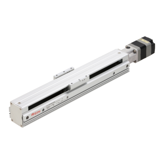
Motorized Linear Slide
EAS Series
OPERATING MANUAL
1
Introduction .............................. 2
2
Safety precautions ................... 4
3
Precautions for use ................... 7
4
Preparation .............................. 10
5
Installation ............................... 15
Thank you for purchasing an Oriental Motor product.
This Manual describes product handling procedures and safety precautions.
• Please read it thoroughly to ensure safe operation.
• Always keep the manual where it is readily available.
Actuator
6
Connection .............................. 24
7
Maintenance ............................ 27
8
specifications ........................... 35
HL-17168-10
Advertisement

Subscribe to Our Youtube Channel
Related Manuals for Oriental motor EAS Series


Summary of Contents for Oriental motor EAS Series
-
Page 1: Table Of Contents
HL-17168-10 Motorized Linear Slide EAS Series Actuator OPERATING MANUAL Introduction ......2 Connection ......24 Safety precautions ....4 Maintenance ......27 Precautions for use ....7 Standards, general specifications ......35 Preparation ......10 Installation ....... 15 Thank you for purchasing an Oriental Motor product. -
Page 2: Introduction
How to use operating manuals Operating manuals for the EAS Series are listed below. Operating manuals supplied with the product vary depending on the type of the product. After reading the manuals, keep them in a convenient place where they are readily available. - Page 3 Introduction Equipped motor list These are the lists of the motor model names that are equipped in the EAS Series. The power supply current capacity, accessories and others of the drivers to be combined with the motorized linear slide are described in the OPERATING MANUAL Driver.
-
Page 4: Safety Precautions
Safety precautions Safety precautions The precautions described below are intended to prevent danger or injury to the user and other personnel through safe, correct use of the product. Use the product only after carefully reading and fully understanding these instructions. You must not operate the motorized linear slide (operate the equipment for the specified purpose) if the machine in which the motorized linear slide is installed does not satisfy the related safety standards. - Page 5 Safety precautions • Assign qualified personnel the task of installing, wiring, operating/controlling, inspecting and troubleshooting the motorized linear slide. Failure to do so may result in fire, electric shock, injury or damage to equipment. • Take measures to keep the moving parts in position for vertical operations such as elevator applications.
- Page 6 Safety precautions • Do not use the motorized linear slide beyond its specifications. Doing so may result in electric shock, injury or damage to equipment. • Keep your fingers and objects out of the openings in the motorized linear slide. Failure to do so may result in fire, electric shock or injury.
-
Page 7: Precautions For Use
Precautions for use Precautions for use This chapter covers limitations and requirements the user should consider when using the product. „ General z Always use the supplied cable or accessory cable to connect the motorized linear slide and driver. In the following condition, an appropriate accessory cable must be purchased separately. •... - Page 8 Precautions for use „ Temperature z Use the motorized linear slide equipped with the AZ Series in conditions where the motor surface temperature will not exceed 80 °C (176 °F). The motor surface temperature may exceed 80 °C (176 °F) under certain conditions (ambient temperature, operating speed, duty cycle, etc.).
- Page 9 Precautions for use z How to fix the cable Fix the cable at the positions near the connector so as to apply no stress on the connector part. Take measures so as to apply no stress on the connector by using wide clamps or by fixing at two places. In the case of the EAS2 type equipped with the AZ Series, fix both end of the cable covering part.
-
Page 10: Preparation
Preparation Preparation This chapter explains the items you should check, as well as the name of each part. Checking the product Verify that the items listed below are included. Report any missing or damaged items to the Oriental Motor sales office from which you purchased the product. - Page 11 E A S 4 R N X - D 0 2 5 - A Z M K D - 3 10 11 12 Series name EAS : EAS series 2 : Width 40 mm, Height 38 mm (Width 30 mm, Height 38 mm) Linear slide size * 4 : Width 58.4 mm, Height 60 mm (Width 45 mm, Height 60 mm)
- Page 12 E A S M 4 R N X D 0 2 5 A Z M K Series name EASM : EAS series 2 : Width 40 mm, Height 38 mm (Width 30 mm, Height 38 mm) Linear slide size * 4 : Width 58.4 mm, Height 60 mm (Width 45 mm, Height 60 mm)
- Page 13 Preparation Names of parts In-line motor mounting type Parallel motor mounting type Table Coupling case Pulley cover Table Top cover Top cover Motor Motor Sensor mounting rail Sensor mounting rail „ Mechanism of the parallel motor mounting type Tension adjustment Pulley springs *2 Motor mounting screws...
- Page 14 Preparation z Motorized linear slide equipped with the AR Series The following figure show models for the electromagnetic brake type and AC power input. Protective Earth Terminal Electromagnetic brake Motor Electromagnetic brake cable Motor cable Connector cover...
-
Page 15: Installation
Installation Installation Location for installation The motorized linear slide has been designed and manufactured to be incorporated in general industrial equipment. Install them in a well-ventilated location that provides easy access for inspection. The location must also satisfy the following conditions: •... - Page 16 Installation Installing the motorized linear slide The motorized linear slide can be installed in any direction. Taking account of vibration prevention as well as deflection of the motorized linear slide, install it on a metal surface of sufficient strength (thickness 10 mm or more). Secure so that the entire area of the bottom face of the motorized linear slide contacts the mounting plate.
- Page 17 Installation „ Mounting screw Length from the Model Screw size Tightening torque mounting plate EAS2 2.4 N·m (340 oz-in) 4 mm or less EAS4 5 N·m (710 oz-in) 6 mm or less EAS6 5 N·m (710 oz-in) 8 mm or less About the length of mounting screws and positioning pins from the mounting plate, be sure to observe the specified value.
- Page 18 Installation „ Release the electromagnetic brake When moving the table of the electromagnetic brake type manually, connect the 24 VDC power supply for electromagnetic brake to release the electromagnetic brake. z Specifications of a power supply for electromagnetic brake Model Voltage Current capacity EAS2...
- Page 19 Installation Changing the motor cable leading direction The motor cable leading direction can be changed according to the space of equipment. • When changing the motor cable leading direction, remove the load, and perform in a state where the motorized linear slide is placed in a horizontal position. Doing the operation in a vertical condition may allow the moving part to fall, leading to injury or mechanical damage.
- Page 20 Installation 2. Remove the motor mounting screws, and dismount the motor. EAS2 EAS4 EAS6 Motor mounting screws (M2.5, 2 places) Motor mounting screws (M3, 4 places) Motor mounting screws (M4, 4 places) 3. Change the cable leading direction, and mount the motor. Mount the motor according to the procedure opposite of dismounting it.
- Page 21 Installation 2. Remove the motor mounting screws, and dismount the motor. EAS4 EAS6 Motor mounting screws (M3) Motor mounting screws (M4) Do not loosen or remove the screws other than the motor mounting screws. EAS4 EAS6 Motor mounting screws Motor mounting screws Motor mounting screws Motor mounting screws 3.
- Page 22 Installation 5. Tighten the motor mounting screws with pressing the motor in the direction of arrow so that the motor does not tilt. EAS4 EAS6 Tightening torque: 1 N m (142 oz-in) Tightening torque: 2.4 N m (340 oz-in) 6. Tighten the tension adjustment screws. EAS4 EAS6 Tightening torque:...
- Page 23 Installation „ Load-positioning pin hole and load-positioning pin groove on table The load-positioning pin hole (round hole) and the load-positioning Load-positioning pin groove pin groove are provided on the table. If installation repeatability is required when a load is installed, use these pin hole and pin groove. Load-positioning pin hole (round hole) Load-positioning pin hole and load-positioning pin groove...
-
Page 24: Connection
Connection Connection Connecting the driver For details about the connection method of the driver, refer to the OPERATING MANUAL Driver. Grounding the motorized linear slide Use a round terminal when grounding, and make sure to ground with a screw and washer. Ground wires and crimp terminals are not supplied. - Page 25 Connection z 3) Grounding the Protective Earth Terminal of the motor Be sure to ground the Protective Earth Terminal of the motor. • Grounding wire: AWG18 (0.75 mm ) or more • Screw size of Protective Earth Terminal: M4 • Tightening torque: 1.2 N·m (170 oz-in) Grounding Protective Earth Terminal „...
- Page 26 Connection „ Connection example for the sensor set PAES-SY-2X/Y, PAES-SY-4X/Y, PAES-SY- 6X/Y (PNP type) The connection example is shown based on the following conditions. • Home-seeking mode: 3-sensor mode • Logic of +LS output and −LS output: Normally closed • Logic of HOMES output: Normally open PAES-SY-2X/Y PAES-SY-4X/Y PAES-SY-6X/Y...
-
Page 27: Maintenance
Maintenance Maintenance This chapter explains the maintenance items in order to operate motorized linear slide safely and efficiently. If an abnormal condition is noted on the motorized linear slide, discontinue any use and contact your nearest Oriental Motor sales office. Inspection item and timing If the motorized linear slide is operated eight hours a day, perform maintenance according to the applicable period specified in the table below. - Page 28 Maintenance Grease lubrication Detach the side cover and top cover, and apply grease referencing the re-greasing interval in the table below. Grease application Re-greasing interval Type of grease Grease amount position • Every six months • Every 100 km (62 mi.) in AFF Grease Apply grease so as to spread it over the Ball screw, guide rail...
- Page 29 Maintenance Checking the belt (Parallel motor mounting type) Detach the pulley cover, and check the belt condition according to the items in the table below. As the result of checking, replace the belt if abnormality is detected. Refer to p.30 for how to replace the belt. Inspection interval Every 500 km (310 mi.) in mileage •...
- Page 30 Maintenance Adjusting the belt tension and replacing the belt Adjust the belt tension of the parallel motor mounting type, or replace the belt. • When adjusting the belt tension or replacing the belt, remove the load, and perform in a state where the motorized linear slide is placed in a horizontal position.
- Page 31 Maintenance 3. Loosen the tension adjustment screws. When loosening the screws, tension of the belt will be adjusted properly by the strength of springs. Model Nominal size EAS4 EAS6 Three turns or less To prevent the tension adjustment screw from falling off, keep three turns or less when turning the screw.
- Page 32 Maintenance Replacing the motor • When replacing the motor, remove the load, and perform in a state where the motorized linear slide is placed in a horizontal position. Doing the operation in a vertical condition may allow the moving part to fall, leading to injury or mechanical damage. ·...
- Page 33 Maintenance z Replacement procedure 1. Remove the pulley cover fixing screws, and detach the pulley cover. Pulley cover Pulley cover xing screws (M3) 2. Remove the motor mounting screws. Model Nominal size EAS4 EAS6 3. Dismount the motor and remove the belt. 4.
- Page 34 Maintenance 6. Loosen the tension adjustment screws. When loosening the screws, tension of the belt will be adjusted properly by the strength of springs. Three turns or less To prevent the tension adjustment screws from falling off, keep three turns or less when turning the screw.
-
Page 35: Standards, General Specifications
Standards, general specifications Standards, general specifications Standards „ UL Standard and CSA Standard Check the “APPENDIX UL Standards” of each product for recognition information about UL Standards of the equipped motor. „ EU Directives z CE Marking Motors for the AC power input type are affixed the CE Marking under the Low Voltage Directive and EMC Directive. Low Voltage Directive Applicable Standards: EN 60034-1, EN 60034-5, EN 60664-1 For the motorized linear slide equipped with the AR Series, they are certified by TÜV Rheinland under the EN 60034-1. - Page 36 • Please contact your nearest Oriental Motor o ce for further information. Singapore Korea Technical Support Tel:(800)468-3982 Tel:1800-8420280 Tel:080-777-2042 8:30 to 5:00 , P.S.T. (M-F) A.M. P.M. www.orientalmotor.com.sg www.inaom.co.kr 7:30 to 5:00 , C.S.T. (M-F) A.M. P.M. www.orientalmotor.com Tel:1800-806161 Hong Kong Branch Tel:+55-11-3266-6018 www.orientalmotor.com.my...
Need help?
Do you have a question about the EAS Series and is the answer not in the manual?
Questions and answers