Advertisement
Quick Links
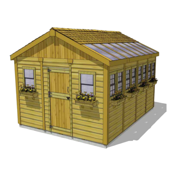
Thank you for purchasing
a 12x16 SunShed Garden
Shed from Outdoor Living
Today. Please take the time
to identify all the parts prior
to assembly.
Safety Points and Other Considerations
Our products are built for use based on
proper installation and normal residential
use, on level ground. Please follow the
instruction manual when building your
shed and retain the manual for future
maintenance purposes.
Some of the safety and usage measures you may wish to consider include:
-snow load ratings vary by geographical location. If heavy or wet snowfall occurs, it is advisable to sweep the
snow off the roof(s).
-if the product is elevated, any structural and building code requirements are solely the customer's
responsibility, and should be abided by.
-in high or gusty wind conditions it is advisable to keep the structure securely grounded.
-have a regular maintenance plan to ensure screws, doors, windows and parts are tight.
Customer agrees to hold Outdoor Living Today free of any liability for improper installation,
maintenance and repair of any of our products.
In the event of a missing or broken piece, simply call the Outdoor Living Today Customer
Support Line @ 1-888-658-1658 within 30 days of the delivery of your purchase. It is our
commitment to you to courier replacement parts, free of charge, within 10 business days of
this notification. Replacement parts will not be provided free of charge after the 30 day grace
period.
Outdoor Living Today
12x16 SunShed Garden Shed
with Cedar Roof
Assembly Manual
www.outdoorlivingtoday.com
Page 1
Revision #1.3
Jan 18, 2021
sales@outdoorlivingtoday.com
Advertisement

Related Manuals for OLT 12x16 SunShed


Summary of Contents for OLT 12x16 SunShed
- Page 1 12x16 SunShed Garden Shed with Cedar Roof Assembly Manual Revision #1.3 Jan 18, 2021 Thank you for purchasing a 12x16 SunShed Garden Shed from Outdoor Living Today. Please take the time to identify all the parts prior to assembly. Safety Points and Other Considerations...
- Page 2 Thank you for purchasing our 12x16 Sunshed Garden Shed. Please take the time to identify all the parts prior to assembly. 1. Floor Section Parts List - Page 2 Steps Floors 1 - 11 4 - 45 1/2” x 75” - Floor Joist Frames - Large 4 - 45 1/2”...
- Page 3 4. Trim & Miscellaneous Section Steps Outer Wall Trim & Dutch Door 67 - 80 14 - 1/2” x 4 1/2” x 45 1/4” - Bottom Skirting (Bevel) 1 - 1/2” x 2 1/2” x 79” - Narrow Door Trim 2 - 1/2”...
- Page 4 12x16 SUNSHED WITH CEDAR ROOF HARDWARE SHEET Hardware Kit (Provided) 1 1/2” 670 pcs 490 pcs 2 1/2” Finishing 230 pcs 2” 80 pcs 1 1/2” Shingle 28 pcs 2” Black Headed 2 pcs 485 pcs 1 1/4” Square Drive Bit 1”...
- Page 5 Exploded view of all parts necessary to A. Floor Section complete Floor Section. Identify all parts prior to starting. Note, Floor Footprint is 182” deep x 141 1/2” wide. Plywood Floor (4) 66 1/2” x 45 1/2” Plywood Floor (4) 75”...
- Page 6 You can find the Square Drive Bit for the screws in with the Hardware Kit Bag. When correctly positioned, attach each Joist with 4 - 2 1/2” screws (2 per end). Complete all Floor Frame and Joist connections. You can find the Square Drive Bit for the screws in with the Hardware Kit Bag.
- Page 7 Attach Floor Runners to Floor Frames with 13 - 2 1/2” screws per completed runner length (39 Total). For Wide Floor Runner use 4 screws in the 56” pieces and 5 screws in the 70” piece. For the 3 1/2” Floor Runner use 5 screws for the 72” pieces and 3 screws for the 38” pieces. Foundations Note: The floor will be flipped over and floor runners will sit on your foundation.
- Page 8 Edge without Floor Runner Wide Floor Runner With a helper, flip remaining floor section over onto your foundation. Edge of frame without floor runner should land on wide floor runner. To attach floor sections together attach each 75” Frame to 66 1/2” Frame with 3 - 2 1/2” screws (36 Total).Use 2 screws on both sides to attach horizontally.
- Page 9 Hint: Use a chalk line to mark location of floor joists to determine screw placement. With Floor Plywood pieces in position, attach with 1 1/4” screws. Use screws every 16” (approximatley 120 total). The plywood is cut slightly smaller than floor framing. Keep plywood seams tight.
- Page 10 Important: Pilot hole ALL 2x3 Wall Studs with 1/8” drill bit prior to screwing. This will make it much easier to attached together. Pilot Bottom Wall Plate Hole Plate first. Parts (Step 12) Hardware (Step 12) Starting with Solid Wall Panels, carefully lay Solid Wall Panels S1 - 2 1/2”...
- Page 11 Rear Window Wall Optional: Small bead of Caulk on wall frame first. Side Solid Wall Position rear Window Wall Panel into place on plywood floor. Butt both vertical wall studs of side and rear walls together and attach with 3 - 2 1/2” screws. Screw at the bottom, middle and top of stud to secure properly.
- Page 12 Important: Pilot hole studs first. Attach a Double Window Wall Panel in corner. Attach as per Step 14. Start positioning and securing remaining Double Window Walls. Attach wall studs together as per Step 14. Wall panel will sit flush with floor framing at front of shed.
- Page 13 Parts (Step 20) Hardware (Step 20) Lineup Narrow Wall so flush with each other on the Narrow Wall Panel S1 - 2 1/2” Screws outside. Attach Studs together with 3 - 2 1/2” screws as (12” x 73”) x 1 x 3 total per Step 14.
- Page 14 Part (Step 23 - 24) Hardware (Step 23 - 24) Locate Door Header and Door Header Door Header S3 - 2” Screws Spacers. Lineup three pieces together so they (1 1/2” x 7 1/4” x 45 1/2”) x 1 x 13 total are flush to creater a larger piece, attach with Door Header Spacer 6 - 2”...
- Page 15 Advice: Prior to fastening walls and installing rafters, take time to confirm your walls are level, square and plumb. Measure diagonal at top and bottom of walls corner-to-corner. This should be approximately 223 1/2”. More importantly, if measurements are not within 1/4”, your walls are not square. Adjusting now will make it easier to the roof section later Important: If walls are not lining...
- Page 16 Parts (Steps 27) Hardware (Steps 27) Position and attach F & R Riser Plates on F&R Riser Plates S1 - 2 1/2” Screws top of Front and Rear Wall Frames. attach with (1 1/2” x 2 1/2” x 70 3/4”) x 16 total 4 - 2 1/2”...
- Page 17 Top and Side plates flush Parts (Steps 30) Hardware (Steps 30) Position and attach Side Top Plates on Side Side Top Plates S2 - 1 1/4” Screws Riser Plates. 65 3/4” side plates are on the outside (3/4” x 2 1/2” x 45 1/2”) x 2 x 24 total with the 45 1/2”...
- Page 18 Flashing overhangs outside of rear wall Place completed Gable Section so framing sits flush with the inside of the Top Wall Plate. It should also be centered side-to-side on the Top Wall Plate. Gable Flashing overhangs wall on the outside. Temporarily attach Gables to Top Wall Plate with 4 - 2” screws . Gables may need slight adjustment in Step 45 when attachment will be completed with an additional 6 screws.
- Page 19 C. Rafter Section Ridge Boards Connectors (3) Ridge Boards 45 1/2” (2) Ridge Boards 91” (3) Polygal Roof Side Rafters (24) Polygal Support Cleats 48” (12) 38” (4) Soffits (4) Gussets (4) Important: Locate all parts necessary to assemble each Rafter Section prior to beginning. Parts for One Rafter Section (Polygal Side): Parts for Other Rafter Section (Non-Polygal Side): 12 - 1 1/2”...
- Page 20 Completed Ridge Board 2 1/2” Screws into Doubled up Rafters Important: Pilot hole Ridge Board to prevent splitting Soffits Parts (Steps 34 - 37) Hardware (Steps 34 - 37) Lay out 12 Rafters, 2 Soffits and the Ridge Boards S1 - 2 1/2” Screws completed Ridge Board from Step 33 on level (3/4”...
- Page 21 Important: Pilot hole Soffit to prevent splitting Attach end Soffit Board flush to ends of outside Rafters with 2 - 1 1/4” screws per Rafter end. Complete both outside Rafter/Soffit connections first. Measure and position interior Rafters as illus- trated above. When positioned correctly, attach Soffits to remaining Rafters with 2 - 1 1/4” screws/rafter.
- Page 22 Gable Notch Slide bottom of Ridge Slight gap between Board into notch of Wall and Soffit. Gable With the assistance of two or more helpers and some ladders, slide first Rafter Section up onto Gable Framing until bottom of Ridge Board slips into gable notch. Position Rafters so they sit evenly on Gable Framing from side to side.
- Page 23 136 1/2” 136 1/2” 136 1/2” Take the inside-to-inside measurment between Top Wall Plates and Bottom Wall Plates at the front, middle, and rear of your shed. These measurments should each be approximatley 136 1/2”, but more importantly, if they are not within 1/4” of each other, your walls are not square. Advice: It may be helpful to use a clamp to help hold Ridge Boards together...
- Page 24 Front Rear Important: If Gable framing does not line up with Rafters, remove temporary 2” screws from Gable framing. Re align gable and then secure. Hardware (Steps 45) With both Rafter Sections correctly aligned, secure Gable Framing to S3 - 2” Screws both outside Rafters with 8 - 2”...
- Page 25 Once walls are confirmed to be square and plumb, attach the remaining 3 Gussets with 10 - 2” screws per Gusset. Gussets attach to single Rafters. Attach remaining screws to Gusset that was attached in Step 46. Important: Pilot hole ends of Gusset to prevent splitting. Attach all Single and Double Rafter Brackets where Rafters meet Top Wall Plates inside of shed.
- Page 26 1/4” Gap Important: Pre drill pilot holes to prevent splitting! Parts (Step 49) Position Polygal Support Cleats alongside Polygal Support Cleats Short Rafters. Leave a 1/4” gap down from top of Rafter. The (3/4” x 3/4” x 38”) x 4 shorter Cleat is for the Rafters with a Gusset attached.
- Page 27 Long Roof Panel Shingles flush Roof Plywood 1/8” with plywood from rafter end. Shingles overhang plywood on outside Parts (Step 50 - 54) Identify Roof Panels. There are 4 Long Roof Panels and 4 Long L&R Roof Panels Short Roof Panels. Start on the long side of roof (side without (48”...
- Page 28 Locate 2nd Center Roof Panel and position so plywood is 1/8” from end of Rafters as per Step 50. From side-to-side, make sure Roof Panel is sitting equally on rafters. When positioned correctly, screw down with 2 - 2 1/2” screws into outside lower shingles. Shingles overhanging outside of roof plywood Lift up and place remaing Long Outside Roof Panel on Rafters.
- Page 29 Repeat Steps 52 - 54 to attach remaining panels on short roof side. Align evenly at roof peak. Roof Filler Shingles are included to cover roof seams. Starting at the bottom, slide the first Long shin- gle in until flush with other bottom shingles. Parts (Steps 57 - 59) Hardware (Steps 57 - 59) Filler Shingles - Long x 21...
- Page 30 4 - 1 1/4” Screws into each bracket 4 - 90 degree Simpson Ties / Gable. Hardware (Step 60) Position 4 - 90° Metal Brackets onto the roof plywood and S2 - 1 1/4” Screws outside Rafter and secure with 4 - 1 1/4” screws each. x 32 total Complete for both Gables.
- Page 31 Place 3rd Ridge Cap 8” back from 2nd (enough to cover shingle nails). Attach 3rd Ridge Cap as per Step 62. Continue to position and attach Ridge Caps until half the roof is complete. From opposite side, position and attach Ridge Caps as described above. One Ridge Cap is cut shorter to fit in the cen- ter of the roof.
- Page 32 Drill pilot holes with 1/8” bit through Polygal Panel and Polygal Support Cleats. Once aligned, with 6 - 1” screws, secure panel to Polygal Support Cleats. Polygal is delicate, tight- en screws a half turn at a time so screws are flush with top of Polygal Panel. Use 3 - 1” screws to secure Polygal Panel to underside of Roof Plywood.
- Page 33 E. Miscellaneous Section Pentagon Detail Polygal Ridge Polygal Ridge Plate (2) Horizontal Gable Trim Angle Cut Facia (4) Caps Center (3) Caps Mid (4) Center (2) Facia Nailing Strips (6) Polygal Ridge Horizontal Gable Trim Caps Outer (2) Outside (4) Above Door Side Facia Trim (2)
- Page 34 Rear of Shed Side of Shed Rear of Shed Hardware (Step 67) Attach Bottom Skirting - Bevel around the base of the 1 1/2” - Finishing Nails shed. Skirting will hide floor framing. Gaps on outside will be cov- x 56 total ered by trim pieces later.
- Page 35 Top Door Bottom Door 3/4” Screws 2” Screws Parts (Step 69) Hardware (Step 69) Attach Door hinges to Top and Bottom Dutch Dutch Door SB2 - 2” Black Screws Door sections. Top Door has trim overhanging door at (Top ) x 1 x 8 total bottom while bottom door has trim recessed slightly.
- Page 36 Slight gap. Top Trim over- 1/4” gap on inside. laps Bottom Trim to pre- vent water from getting in Parts (Step 71) Hardware (Step 71) Place the Top Dutch Door panel into place and Dutch Door SB2 - 2” Black Screws gap top and bottom trims on the outside about 1/8”...
- Page 37 Trim out side walls by attaching Top Wall Trim. Position with thick end of Bevel downwards at top of wall, tight against Soffits. Attach with 4 - 1 1/2” Finishing Nails per piece. Complete both sides. Parts (Step 73) Hardware (Step 73) Top Wall Trim N1 - 1 1/2”...
- Page 38 Side Trim Wide Trim Parts (Step 76) Hardware (Step 76) Attach Wide Corner Trims over Filler Trims. Wide Corner Trims N1 - 1 1/2” Finishing Wide Trim will cap Side Trims. Attach with 8 - 1 1/2” (1/2” x 5 1/2” x 90”) x 4 Nails Finishing Nails per piece.
- Page 39 Outside (2) Center (3) Mid (4) Polygal Ridge Cap 5 1/2” wide 3 1/2” wide 2 1/2” wide overhangs Rafter by approx. 1/4” Parts (Step 78 - 80) Locate all Polygal Ridge Caps (4 Mid, 2 Outside, and Outside Polygal Ridge Caps 3 Center).
- Page 40 Parts (Step 81) Attach Facia Cleat Short centered on underside of Facia Cleat Short Polygal Side Battens, flush to edge. Attach Facia Cleat Long (3/4” x 1 1/2” x 36 1/2”) x 2 to underside of Battens on Non-Polygal side, flush edge to Facia Cleat Long edge.
- Page 41 Parts (Step 83, 85) Hardware (Step 83, 85) Attach Side Facia to roof Rafter ends. Side Facia N1 - 1 1/2” Finishing Nails There are 3 Side Facia pieces per side. (3/4” x 5 1/2” x 49 1/2”) x 4 x 48 total Secure with 8 - 1 1/2”...
- Page 42 Attach remaining Side Facia to roof Rafter ends as per Step 83. Side Facia fits under- neath Polygal Panels and Polygal Ridge Caps. Parts (Step 86) Hardware (Step 86) Attach Door Trim to cover seam Left Door Trim N1 - 1 1/2” Finishing Nails between Window Wall Panel and Narrow (1/2”...
- Page 43 Parts (Step 88) Hardware (Step 88) Locate Horizontal Gable Trims for Horizontal Gable Trims N1 - 1 1/2” Finishing Nails both front and rear of shed. Position equally (3/4” x 4 1/2” x 42”) x 2 x 36 total over Gable and Wall seam. Attach each piece (3/4”...
- Page 44 Dabs of caulk in window channel Parts (Step 91) Locate Window Inserts. There are two type Regular and Narrow Regular Window Inserts (for double window walls). Before installing, dab caulk in siding channel on both sides and across top of window opening. This will prevent water Narrow Window Inserts from getting in beind window.
- Page 45 Hardware (Step 93 ) Assemble Flower Box Kits with Assembly Instructions included. S1 - 2 1/2” Screws Position completed Flower Box below bottom of window trim and secure x 16 total with 2 - 2 1/2” screws. Screw from inside of box into the center wall Parts (Step 93) stud.Attach second screw 2”...
- Page 46 Place next Potting Shelf against wall framing and end of Long Shelf framing. Attach with 2 - 2 1/2” screws as per Step 97 to first shelf and wall framing. Use a level to confirm shelving is square and level. Attach legs as previously illustrated. Screw to wall stud and up into the underside of shelf framing.
- Page 47 Completed 12x16 SunShed Note; Our Sheds are shipped as an unfinished product. If exposed to the elements, the western red cedar lumber will weather to a silvery-gray color. If you prefer to keep the cedar lumber looking closer to the original color, we...