
Related Manuals for Appostar Grand POS GP-3460


Summary of Contents for Appostar Grand POS GP-3460
- Page 1 All manuals and user guides at all-guides.com http://www.appostar.com Grand POS GP-3460 User’s Manual Edition: JAN 2014 Version 1.00...
- Page 2 All manuals and user guides at all-guides.com PREFACE Feder ral Com mmunic cations s Comm missio n (FCC This equ uipment h as been t ested and d found to o comply w with the l imits for a a Class A digital de evice, pur rsuant to...
- Page 3 The material in this document is for information purpose and is subject to change without prior notice. APPOSTAR has made every effort to ensure that this user’s manual is accurate and complete. However, no liability is assumed for any errors and omissions that may have occurred.
- Page 4 All manuals and user guides at all-guides.com PREFACE Important Safety Instructions Failure to observe these safety instructions may cause bodily injury, or damage to the product. Read these instructions carefully and keep this user’s manual in an accessible location for future reference. The product may cause a fire or electric shock when it is used improperly.
-
Page 5: Table Of Contents
All manuals and user guides at all-guides.com Table of Contents CHAPTER 1 PRODUCT OVERVIEW ........... 2 1.1 U ..................2 NPACKING 1.2 A ..................3 PPEARANCE 1.3 I/O I ..................5 NTERFACE 1.4 S ..................6 PECIFICATION CHAPTER 2 HARDWARE INSTALLATION ........ 8 2.1 M (MSR) I .......... -
Page 6: Chapter 1 Product Overview
All manuals and user guides at all-guides.com PRODUCT T OVERVIEW CHAP PTER 1 1 PRO ODUCT T OVER RVIEW Welco The Gra nd POS s series is th he All-in-O One POS Terminal which is conceptu ualized to save pow wer cons umption t to meet t... -
Page 7: Appearance
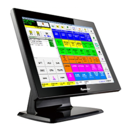
All manuals and user guides at all-guides.com PRODUCT OVERVIEW 1.2 Appearance Front View 15” LCD touch panel MSR module (optional) / Attachable on both sides Front bezel Base Rear View Hinge cover I/O Cover Storage for power adaptor GP-3460 POS Terminal... - Page 8 All manuals and user guides at all-guides.com PRODUCT OVERVIEW Side View Tilt angle 0 ~ 85 degree 85° GP-3460 POS Terminal...
- Page 9 All manuals and user guides at all-guides.com PRODUCT O OVERVIEW 1.3 I/ /O Inter rface Port scription Descrip ption SPEAKER 1.5W int tegrated x rial port wi ith DB9/M POWER 1 X Powe er ON / OF rial port wi ith RJ45 BUTTON switch...
-
Page 10: Specification
All manuals and user guides at all-guides.com PRODUCT OVERVIEW 1.4 Specification Model Name GP-3460 System Main Board IAT1-2550 Intel Atom D2550 1.8 GHz Dual Core Chipset Intel NM10 Express Memory 1GB DDRIII RAM Display Size 15” TFT-LCD with touch panel Display Resolution 1024 x 768 2.5”... - Page 11 All manuals and user guides at all-guides.com PRODUCT OVERVIEW Mechanical Housing Color Black Construction ABS + SECC Dimension(W x D x H) 350 x 242 x 320 mm NET / GROSS N.W. 5.8 kg / G.W. 7.7kg GP-3460 POS Terminal...
-
Page 12: Chapter 2 Hardware Installation
All manuals and user guides at all-guides.com HARDWARE INSTALLATION CHAPTER 2 HARDWARE INSTALLATION Before starting any hardware configuration, ensure that the system is powered off and the power cord is disconnected to prevent possible damage to the product. 2.1 Magnetic Stripe Reader (MSR) Installation An optional MSR can be installed in both right/left side of GP-3460. -
Page 13: Nstallation
All manuals and user guides at all-guides.com HARDWARE INSTALLATION 2.2 VFD/LCD Customer Display Installation Step1 Use flat screw driver to remove the stand cover and break up the lid at the bottom of the cover. Step2 Fit in the bracket and screw it up. Step3 Install the VFD onto the bracket and lead the cable through the stand to the RJ45 COM port. -
Page 14: Second Lcd Installation
All manuals and user guides at all-guides.com HARDWARE INSTALLATION 2.3 Second LCD Installation Step1 Use flat screw driver to remove the stand cover and break up the lip at the bottom of the cover. Step2 Fit the bracket in position with 2 screws. Step3 Reinstall the stand cover. -
Page 15: Chapter 3 Software Installation
Microsoft Windows platforms. Insert the driver CD into your CD-ROM drive. Windows will automatically detect it and the Appostar Driver Installer appears on the screen. If not, locate the Setup.exe file at CD:\ and double-click it to execute the one-step driver installation. - Page 16 All manuals and user guides at all-guides.com BOARD SETTING e. After Chipset Driver(INF) installed, f. Select “Install this driver click No to continue. software anyway” in Windows Security window to continue the installation procedure. g. Select “Install” in Windows Security h.
-
Page 17: Peripheral Device Driver Installation
All manuals and user guides at all-guides.com BOARD SETTING 3.2 Peripheral Device Driver Installation 3.2.1 Touch COM Driver Installation a. Click Peripheral Devices b. Click Touch Panel. c. Click Next on the Welcome screen d. Ignore the “Install PS/2 interface to continue. - Page 18 All manuals and user guides at all-guides.com BOARD SETTING g. Select the “Support Multi-Monitor h. Select the Destination Folder or System” option. Click Next to use the default one listed. continue. i. Type a Folder name or use the j. A progress window appears. Please default one listed.
-
Page 19: Chapter 4 Board Setting
All manuals and user guides at all-guides.com BOARD SETTING CHAPTER 4 BOARD SETTING 4.1 Main Board Jumper Setting JCMOS1: Clear CMOS Header * Placing the jumper on pin2-3 allows user to restore the BIOS safe setting and the CMOS data. Please carefully follow the procedures to avoid damaging the mainboard. - Page 20 All manuals and user guides at all-guides.com BOARD SETTING JPC2 Voltage Switch jumper for JCOM2 ports This header is for controlling the Pin1of COM ports to switch Ring/ 5V/12V. Pin 1-2 Close: Pin1=5V (Default) Pin 3-4 Close: Pin1=Ring Pin 5-6 Close: Pin1=12V Remark: Max output: 12V@500mA for each COM port...
-
Page 21: Chapter 5 Troubleshooting
All manuals and user guides at all-guides.com APPENDIX Chapter 5 TROUBLESHOOTING This chapter provides suggestions on how to locate and solve problems that may arise while using your GP-3460. If you cannot solve a problem with the following information, contact your dealer for further assistance. With the power on, there is no image or abnormal display on the terminal screen.
Need help?
Do you have a question about the Grand POS GP-3460 and is the answer not in the manual?
Questions and answers